FR
EN
Proper Use
This wenglor product has to be used according to the follow-
ing functional principle:
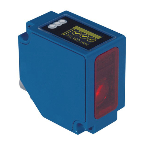
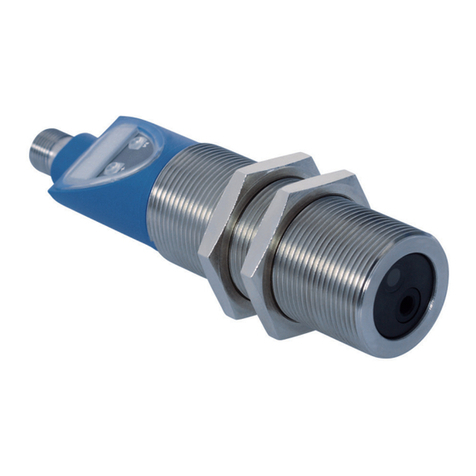
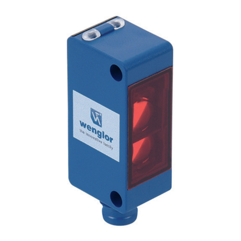
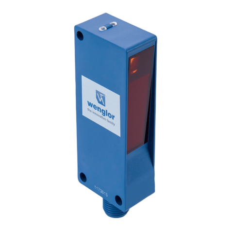
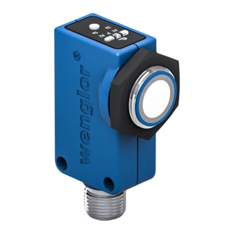
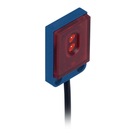
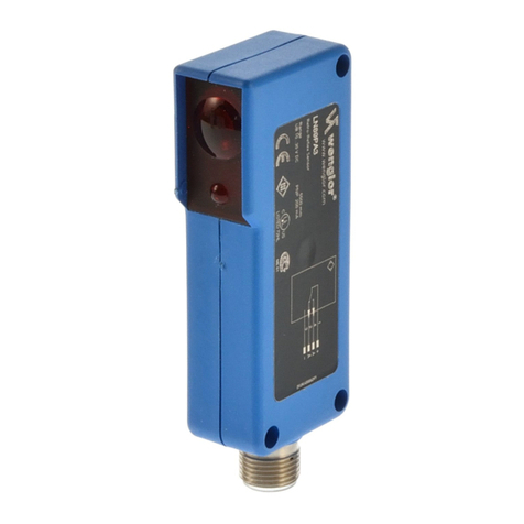
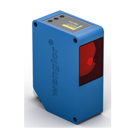
Reflex Sensors
The transmitter and the receiver are integrated into a single
housing.
The sensor evaluates light reflected from the object, if the ob-
ject passes within the selected range, the output is switched.
Bright objects reflect more light than dark objects and can
thus be recognized from greater distances.
Safety Precautions
•This operating instruction is part of the product and must be
kept during its entire service life.
•Read this operating instruction carefully before using the
product.
•This product is not suitable for safety applications.
•Installation, start-up and maintenance of this product has
only to be carried out by trained personal.
•Tampering with or modifying the product is not permissible.
•Protect the product against contamination during start-up.
•These products are not suited for safety applications.
Technical Data
Range 800 mm
Switching Hysteresis < 15 %
Light Source Infrared Light
Wave Length 880 nm
Service Life (T = 25 °C) 100000 h
max. Ambient Light 10000 Lux
Supply Voltage 10...30 V
Current Consumption (Ub = 24 V) < 40 mA
Switching Frequency 1600 Hz
Response Time 313 µs
On-/Off-Delay (RS-232) 0...5 s
Temperature Drift < 5 %
Temperature Range –25...60 °C
Switching Output Voltage Drop < 2,5 V
PNP Switching Output/Switching Current 200 mA
Short Circuit Protection yes
Reverse Polarity Protection yes
Overload Protection yes
Lockable yes
Teach Mode NT, MT
Adjustment Teach-In
Housing Stainless Steel 316L
Degree of Protection IP68 / IP69K
Connection M12×1
Protection Class III
Output
PNP NO/NC switchable yes
RS-232 with Adapterbox yes
Part Number OTII802C0103 OTII802C0203
Optic cover PMMA Glas
Utilisation
Ce produit wenglor doit être utilisé selon le mode de fonction-
nement suivant:
Détecteur optique de proximité
Emetteur et récepteur sont logés dans un seul et même
boîtier.
Ces détecteurs exploitent la lumière réfléchie par l’objet.
Si l’objet atteint la portée réglée, la sortie commute. Les ob-
jets clairs réfléchissent mieux la lumière que les objets foncés
et peuvent donc être détectés à des distances plus grandes.
Conseils de sécurité
•Ces instructions de Service sont une partie intégrante du
produit et doivent être conserves durant toute la durée de
vie du produit.
•Lire les Instructions de Service avant la mise en marche.
•Installation, raccordement et réglage ne doivent être effec-
tués que par du personnel qualifié.
•Toute intervention ou modification sur le produit ne sont pas
autorisées.
•Lors de la mise en service, protéger l’appareil des saletés.
•Ces produits ne peuvent pas être utilisés pour des applica-
tions soumises aux normes de sécurité.
Données techniques
Distance de travail 800 mm
Hystérésis de commutation < 15 %
Type de lumière Infrarouge
Longueur d’onde 880 nm
Durée de vie (Tu = 25 °C) 100000 h
Ambiance lumineuse max. 10000 Lux
Diamètre du spot lumineux Voir tableau 1
Tension d’alimentation 10...30 V
Consommation (Ub = 24 V) < 40 mA
Fréquence de commutation 1600 Hz
Temps de réponse 313 µs
Temporisation à l’appel/retombée (RS-232) 0...5 s
Dérive en température < 5 %
Température d’utilisation –25...60 °C
Chute de tension sortie de commutation < 2,5 V
Courant commuté PNP sortie de
commutation 200 mA
Protection contre les courts-circuits oui
Protection contre les inversions de polarité oui
Protection contre les surcharges oui
Verrouillable oui
Mode d’apprentissage NT, MT
Mode de réglage Apprentissage
Matière du boîtier Inox V4A
Degré de protection IP68 / IP69K
Mode de raccordement M12×1
Classe de protection III
Sortie
PNP Ouverture/Fermeture commutable oui
RS-232 avec adaptateur oui
Référence OTII802C0103 OTII802C0203
Optique PMMA glass
Complementary Products (see catalog)
wenglor offers Connection Technology providing field wiring
means.
Suiting Mounting Technology No. 140 490
Suiting Connection Technology No.
2
S02
InoxLock Set
Adapter Box A232
Mounting instructions
During operation of the sensors, the corresponding electrical
and mechanical regulations, as well as safety regulations
must be observed. The sensor must be protected from me-
chanical impact. Adjust and securely mount the sensor such
that the spot strikes the object to be detected.
Adjustment
Enabling Teach-In
The sensor is ready for
Teach-In when the red LED
02 is lit up, and it remains in
the ready state for about 10
seconds.
Teach-In is not possible
when the red LED 02 is
blinking.
Reason: Teach-In key was
pressed and held too long.
Repeat “Enabling Teach-In”
above.
Troubleshooting:
Teach-In
Teach-In takes place while
the yellow LED 01 is
blinking.
Teach-In does not take place
when the red LED 02 is
blinking.
Reason: Teach-In 06 key
was pressed and held too
long or not long enough.
Troubleshooting:
The sensor is
ready for operation.
• Press and hold the Teach-In
key 06 until the yellow LED 01
starts blinking.
• Release the Teach-In key 06
immediately.
01
06
02
01
06
02
01
06
02
• Press and hold the Teach-In
key 06 until the yellow LED 01
starts blinking.
• Release the Teach-In key 06
immediately.
01
06
02
01
06
02
01
06
02
Produits complémentaires (voir catalogue)
No. de Technique de montage
appropriée 140 490
Référence connectique appropriée
2
S02
Set de InoxLock
Adaptateur A232
Instructions de montage
Lors de la mise en service des détecteurs respecter les
prescriptions de sécurité, normes et instructions électriques et
mécaniques appropriées. Protéger le détecteur contre toute
influence mécanique pouvant le dérégler ou endommager.
Ajuster et installer fixement le capteur de façon à ce que la
spot atteigne l’objet à détecter.
Réglage
Dévérouillage du Teach-In
Lorsque la LED rouge 02
est allumée, l’apprentissage
Teach-In du capteur est
possible (Durée 10 secondes
environ).
Lorsque la LED rouge 02
clignotte, l’apprentissage
Teach-In est impossible.
Cause : Touche Teach trop
longtemps appuyée. Répéter
«Dévérouillage du Teach-In».
Dépannage :
Apprentissage Teach-In
Le clignottement de la LED
jaune 01 confirme
l'apprentissage.
Le clignottement de la LED
rouge 02 indique que
l'apprentissage a échoué.
Cause : Touch Teach 06
trop longtemps ou pas assez
appuyée.
Dépannage :
Le capteur est prêt.
• Maintenir la touche Teach
06 jusqu’au clignottement
de la LED 01 jaune.
• Relacher immédiatement
la touche Teach 06 .
01
06
02
01
06
02
01
06
02
• Maintenir la touche Teach
06 jusqu'au clignottement
de la LED 01 jaune.
• Relacher immédiatement
la touche Teach 06 .
01
06
02
01
06
02
01
06
02
Functions of pin 2
External Teach-In
The sensor is equipped with an input for external Teach-In
(pin 2). The switching point can be taught in via this input by
applying a voltage of 24 V for approximately
1 second.
Disabling the Teach Key
If 24 V is continuously connected to the external Teach-In
input, the sensor is locked and protected against inadvertent
readjustment.
Switching Between the Teach Modes
Apply 24 V to the Teach-In input for at least 10 seconds, until
the LED changes over from fast to slow blinking.
Switching between the teach modes is possible with the teach
key, and by means of the Teach-In process.
Blinking Normally closed/
Normally open TEACH Mode
1×* NO Normal Teach-In
2× Minimal Teach-In
3× NC Normal Teach-In
4× Minimal Teach-In
*preset configuration
•Each tome a brief pulse is applied to the Teach-In input,
switching to the next Teach-In mode occurs.
•If the Teach-In input is not activated for a period of
15 seconds, the sensor is automatically switched back to
the normal display mode.
•Repeat the Teach-In process in accordance with the setup
instructions.
Additional Functions for activation via the interface:
On-/Off-Delay
Either pull-in or release delay can be activated at the sensor
via the interface. Delay time can be adjusted. The A232
adapter box is required in order to be able to connect the
sensor. The Switching Frequency can be changed via the
interface from 1000 Hz (delivery status) to 1600 Hz.
Switching distance
The minimum distance is equal to the Range × 0,9 (at an am-
bient temperature of 25 °C). All switching distance data refers
to white Kodak paper, matt, 200 g/m², with a surface area of
40×40 cm and with light striking vertically at 90°. Changes
to the switching distance caused by different materials are
shown in the Switching distance diagram.
Material Factor
Kodak paper white 1
paper white 1…1,5
styropor white 1…1,5
metal glossy 1,2…3
metal rusty 0,2…0,6
aluminum black 0,1…0,8
cotton white 0,6
Fonctions du pin 2
Teach-In externe
Le capteur est doté d’une entrée pour l’apprentissage ex-
terne (pin 2). L’apprentissage du point de commutation peut
être réalisé en appliquant une tension de 24 V DC pendant 1
seconde environ.
Désactiver le bouton TEACH
Si 24 V est appliqué de façon continue sur l’entrée Teach-In
externe, le capteur est verrouillé et est protégé des manipula-
tions involontaires.
Changer de mode TEACH
Appliquez 24 V à l’entrée Teach-In externe pendant 10
secondes minimum, jusqu’à ce que la LED passe d’un
clignotement rapide à lent.
Le changement de mode TEACH est alors possible avec le
bouton TEACH en suivant les procédures d’apprentissage.
Clignotement Ouverture/
Fermeture Mode d’apprentissage
1×* NO Apprentissage normale
2× Apprentissage minimale
3× NC Apprentissage normale
4× Apprentissage minimale
*Préréglage
•Chaque fois qu’une brève impulsion est appliquée à l’en-
trée Teach-In, le mode d’apprentissage change.
•Si l’entrée Teach-In n’est pas activée pendant 15 secondes,
le capteur retourne automatiquement au mode normal.
•Répétez les procédures d’apprentissage en suivant les
instructions de mise en service.
Fonctions actives supplémentaires par l’interface:
A l’appel ou à la retombée
Par l’interface une temporisation à la l’appel ou à la retombée
peut être activée sur le détecteur. La temporisation peut être
ajustée. Pour récupérer les paramètres sur PC par l’interface
RS232 un adapteur A232 est indispensable.
La fréquence de commutation peut être changée via l’inter-
face de 1000 Hz (livraison Usine) à 1600 Hz.
Distance de détection
La distance de commutation est la distance de travail
par 0,9 (à température ambiante de 25°). Les distances
de commutation se réfèrent au papier Kodak blanc-mat
de 200 g/m², d’une surface de 40×40 cm et d’un rayon
lumineux perpendiculaire par rapport à la surface du papier.
Des changements de la distance de commutation pour des
autres matériaux vous relevez du diagramme de distance de
commutation.
PVC, grey 0,5
wood, rough, dry 0,4
cardboard black 0,1…0,5
Switching distance = Range × Factor
Causes for Triggering of Contamination Indication
(red LED)
•Contaminated sensor
•Distance between the sensor and the object is too big
•Incorrect installation
•Short-circuit
•Aged emitter diodes
•Unreliable working range
Diagram Contamination Output/Contamination Warning
beginning contamination
Object Object Object
Reflex Mode no contamination
Object Object Object
Object
Switching Status
Contamination Warning
Object
Switching Status
Contamination Warning
Object
Switching Status
Contamination Warning
advanced contamination
Object Object Object
off
off
off
off
on
off
off
off
off
off
off
off
off
on
on
off
off
off
not detected not detecteddetected
not detected not detecteddetected
not detected not detectednot detected
Proper Disposal
wenglor sensoric gmbh does not accept the return of unus-
able or irreparable products. Respectively valid national waste
disposal regulations apply to product disposal.
Matériaux Facteur
Kodak papier blanc 1
papier blanc 1…1,5
styro blanc 1…1,5
métal brillant 1,2…3
métal rouillé 0,2…0,6
aluminium noir 0,1…0,8
coton noir 0,6
PVC gris 0,5
bois 0,4
carton noir 0,1…0,5
Distance de détection = Distance de travail × facteur
Raisos liées à l’indication Encrassement (LED rouge)
•Capteur encrassé
•Distance entre le capteur et l’objet trop importante
•Mauvaise installation
•Court-circuit
•Diodes d’émission en fin de vie
•Distance de travail inadaptée
Diagramme Sortie et signalisation d’encrassement
allumée
allumée
non detécté non detéctédetécté
début d’encrassement
Objet Objet Objet
non detécté non detéctédetécté
Mode réflex pas d’encrassement
Objet Objet Objet
Objet
Signalisation de l’état de
commutation
Signalisation de
l’encrassement
Objet
Signalisation de l’état de
commutation
Signalisation de
l’encrassement allumée
Objet
Signalisation de l’état de
commutation
Signalisation de
l’encrassement
non detécté non detécténon detécté
encrassement avancé
Objet Objet
éteint éteint
éteint éteint éteint
éteint éteint
éteint éteint
éteint éteint
éteint
éteint éteint
éteint
Objet
Mise au rebut écologique
La société wenglor sensoric gmbh ne reprend ni les produits
inutilisables ni les produits irréparables. Les prescriptions na-
tionales en vigueur en matière de mise au rebut des déchets
sont applicables.

