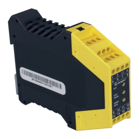
Wenglor SG4-I User manual

Available as PDF only
Status: 17.10.2017
Version: 12
www.wenglor.com
EN
SG4-I
Safety Light Curtain
Operating instructions

2
EN
Table of Contents
1. General 4
1.1 Function and Use for Intended Purpose 4
1.2 Features 4
1.3 Applications Examples 4
1.3.1 Single Curtain Protection 5
1.3.2 Cascading Two Light Curtains 5
1.3.3 Use at Brake Presses 5
1.4 Brief Explanation of Function- and Operating Modes 6
1.5 Explanation of symbols 7
2. Initial Start-Up Flowchart 7
3. Important Notes Concerning Use 8
3.1 General Comments 8
3.2 Securing the Danger Zone 9
3.3 Calculating Safety Clearance per EN ISO 13855 10
3.3.1 Direction of Approach to the Safety Field 11
3.3.1.1 Perpendicular Approach to the Safety Field 11
3.3.1.2 Parallel Approach to the Safety Field 11
3.3.2 Sample Calculations 12
3.4 Minimum Clearance to Reflective Surfaces 13
4. Connection and Installation to the Machine 14
4.1 Installation 14
4.2 Default Settings 16
5. Operating the Light Curtain 17
5.1 Pilot Beam 17
5.2 Adjustment 17
5.2.1 Using the Aligning Tool 17
5.2.2 Adjustment Procedure 18
5.3 Function Modes 19
5.3.1 Safety Operating Mode 19
5.3.2 Start Inhibit and Restart Inhibit 19
5.3.3 Contactor Monitoring 21
5.4 Blanking Options 23
5.4.1 Fix Blanking 23
5.4.1.1 Principle 24
5.4.1.2 Fix Blanking Procedure 26
5.4.1.3 Calculating Safety Clearance 27
5.4.2 Floating Blanking 27
5.4.2.1 Principle 27
5.4.2.2 Floating Blanking Procedure 29
5.4.2.3 Calculating Safety Clearance 29
5.4.3 Auto Floating Blanking 32
5.4.3.1 Principle 32
5.4.3.2 Auto Floating Blanking Procedure 33
5.4.3.3 Calculating Safety Clearance 34
5.4.4 Reduced Resolution 35
5.4.4.1 Principle 35
5.4.4.2 Reduced Resolution Procedure 37
5.4.4.3 Calculating Safety Clearance 38
5.4.5 Summary of Blanking Options 39

3
5.5 Cascading (Linking Several Light Curtains) 39
5.5.1 Principle 40
5.5.2 Cascading Procedure 40
5.5.3 Functions 42
5.5.4 Coding 43
6. Expanding the Light Curtain System 44
6.1 Relay Unit 44
6.2 Muting Module 45
6.3 Connection to a PC 46
6.4 Path-Folding Mirror 47
7. Display 48
7.1 Display of Operating Modes 48
7.2 Diagnostic information 49
8. Condensed Start-Up Instructions 50
9. Inspection Instructions 50
9.1 Inspection Prior to Initial Start-Up 51
9.2 Daily Inspection and Maintenance of the Effectiveness of the Safety De-
vice 51
10. Environmentally Sound Disposal 52
11. Dimensional Drawings 52
11.1 Finger Protection Emitter 52
11.2 Finger Protection Receiver 52
11.3 Hand Protection Emitter 53
11.4 Hand Protection Receiver 53
11.5 Mounting Bracket BEF-SET-33 54
12. Technical Data 54
12.1 Safety Light Curtains 54
12.2 System Components 56
12.2.1 Relay Unit Type 2/Type 4 SG4-00VA000R2 56
12.2.2 Adapter Box RS-232 to A485-232 56
12.2.3 Laser Alignment Aid SZ0-LAH1 56
12.2.4 Mounting Elements 56
12.2.5 Connection Line 57
12.2.6 Connection Cables 57
12.2.7 Interface Cable 57
13. Checklist for Initial Start-Up 58
14. Certification 58
15. EU Declaration of Conformity 59
Due to the fact that they describe the operation of a safety device, these operating instructions are of a binding
nature.

4
EN
1. General
The SG4 light curtain system is a design-approved, electro-sensitive protection equipment (ESPE) in accordance
with EN 61496-1. It’s a class 4 Light Curtain, i.e. it’s an ESPE for which the safety function remains intact even if
several errors occur. Furthermore, it’s a category 4 Safety Light Curtain, and is thus a self-testing safety device.
The light curtain system consists of a emitter module and a receiver module. A muting module and a relay unit are
available as accessory equipment.
1.1 Function and Use for Intended Purpose
The light curtain monitors the safety field between the emitter and the receiver. If the safety field is penetrat-
ed by an obstruction, a switching command is triggered. This switching command may prevent initialization
of a hazardous machine motion, or may stop an action which has already been started.
Use of the light curtain is only permissible if:
• Hazardous motion can be stopped by electrical means using the light curtain’s safety output
• Adequate detection of possible obstruction is assured with existing resolution
• An application of Light Curtain of Category 4 is permissible.
1.2 Features
• Safety device per EN 61496-1
• TÜV approved
• Finger protection: 14 mm resolution, 7 m range
• Hand protection: 30 mm resolution, 20 m range
• Visible red light
• PNP semiconductor safety outputs
• PNP signal output
• Fix Blanking
• Floating Blanking
• Auto Floating Blanking
• Electronically reduced resolution
• Simple cascading
• Serial interface with visualization program
• Restart inhibit
• Monitoring of external relays
• Muting (optional)
• Relay unit (optional)
• Coding
1.3 Applications Examples
Safety protection at:
• Presses
• Saws
• Textile machinery
• Transfer lines, assembly lines
• Automatic insertion equipment
• Packaging machines
• Rotary indexing machines
• Woodworking machines

5
1.3.1 Single Curtain Protection
Example: securing an area
1.3.2 Cascading Two Light Curtains
Example: securing off an area plus side-stepping protection
1.3.3 Use at Brake Presses
Example: floating blanking

6
EN
1.4 Brief Explanation of Function- and Operating Modes
Auto Floating Blanking
This operating mode is the same as Floating Blanking, except that in this case the object (for example a skid carrier
or lifting forks) moves through and exits the safety field. The direction at which the object enters and exits the safety
field, as well as its dwell time within the safety field, must be defined. Any other intrusions into the safety field cause
the safety output to switch and stop hazardous motion.
Cascading
Safety devices can be series connected such that they all drive a single safety output in order to monitor several
safety fields simultaneously. Cascaded safety devices demonstrate the same performance characteristics as a sin-
gle safety device.
Contactor Monitoring
An operating mode for which switching performance of the contacts at an external relay is dynamically monitored.
The contacts must close fully within a specified period of time.
Fix Blanking
This operating mode is required for applications including objects which continuously protrude into the safety field,
thus interrupting specific light beams originating from the safety light curtain. Intrusions into any other point within
the safety field cause the output to switch and stop hazardous motion.
Floating Blanking
This operating mode is the same as Fix Blanking, except that in this case the object (for example a cable or a cutting
edge) is permitted to move within the safety field. Any other intrusions into the safety field cause the safety output
to switch and stop hazardous motion.
Reduced Resolution
This function reduces the resolution electronically. Thus objects that are smaller than the selected resolution don’t
deactivate the safety output. The function can also be used to prevent machining chips from interfering with correct
functioning of the safety light curtain.
Restart Inhibit
A function which prevents a machine from starting up automatically after it has been switched on. The machine can
only be enabled by activating an acknowledgement key.
Safety Operating Mode
In this operating mode, the switching outputs are disabled when the safety field is penetrated. The switching outputs
are automatically enabled after penetration of the safety field is ended.
Safety Output – OSSD (Output Signal Switching Device)
The output of the contactless safety device which is connected to the machine controls. The safety output is deac-
tivated when the safety field is interrupted.
Signal Output
A semiconductor output for auxiliary functions without safety monitoring.
Start-Up Inhibit
This function is activated along with the „Restart Inhibit Function“. When power supply is switched on (e.g. after a
power failure), the safety outputs (OSSD) remain in the off state. Acknowledgement is accomplished by activating
an acknowledgment key.

7
1.5 Explanation of symbols
Points up suggestion and tips, which simplify the handling of the safety light curtain.
Points at a measure to prevent a concrete danger.
Points at functions, which can only be configured by means of software (PC).
2. Initial Start-Up Flowchart
Determine the required safety category
per EN 1050 (severity of injury, frequency and
duration of hazardous motion etc.)
Chapter 3.1
Chapter 3.2
Chapter 3.3
Chapter 5.4
Chapter 3.2
Chapter 3.4
Chapter 4.1
Chapter 4
Chapter 5.2
Chapter 5.3
Chapter 5.3
through
Chapter 5.4
Chapter 9
Chapter 10
Calculate safety clearance
Mechanically install the light curtain
(consider reaching over or under, side-stepping
and distance to reflective objects)
Adjust the light curtain
Select an operating mode
Important! high resolution
èlarge safety clearance
Test the safety functions

8
EN
3. Important Notes Concerning Use
3.1 General Comments
The use of contactless safety devices is regulated by official directives. National and international regulations apply
to the safe utilisation of contactless safety devices, in particular:
• EN standards
• Accident prevention regulations
• EC Machinery Directive
• Occupational health and safety requirements
ESPE may only be used at power operated machinery whose controls can be electrically influenced such that haz-
ardous motion can be stopped immediately in all operating phases.
If other light beams occur in an application (e.g. infrared controllers, emission due to welding sparks or the effects
of stroboscope light), additional measures may be necessary in order to assure that the ESPE does not fail in a
dangerous mode.
Testing must be performed by an expert prior to initial start-up of ESPE. Testing must establish flawless
interaction of the contactless safety device together with the controls of the power operated machinery, and
correct installation in accordance with these safety precautions.
The cascading terminals on the sensor and the receiver may only be used to connect additional Safety
Light Curtains. Connection of other power consumers is impermissible.
The following standards must be observed during use of the light curtain:
EN ISO 13855 Machine safety: arrangement of safety devices in consideration of approach
speeds of body parts
EN ISO 12100 Machine safety: General design guidelines – risk assessment and risk minimization
EN ISO 13857 Machine safety: Safety distances to prevent hazard zones being reached by
upper and lower limbs
EN 349 Machine safety: Minimum gaps to avoid crushing of parts of the human body
EN ISO 13850 Machine safety: emergency stop devices
EN ISO 14119 Machine safety: Interlocking devices associated with guards
All specified data make reference to the following revision level: 17.10.2017
Technical changes to the product described herein, printing errors and/or any possible incompleteness of this prod-
uct description may not be construed as cause for asserting any legal claims whatsoever against wenglor sensoric
GmbH.

9
3.2 Securing the Danger Zone
The danger zone must be secured by means of the light curtain alone, or by means of the light curtain in
combination with additional mechanical safety devices. Reaching around, over and/or under the safety
field must be prevented in any case. It must be impossible to approach the point of danger without passing
through the safety field.
The safety field is located between the line at which light is emitted at the emitter and the line at which light
is received at the receiver. The boundaries of the safety field are identified on the devices.
Examples:
Incorrect Correct
Side-Stepping
Reaching Under
Reaching Over

10
EN
3.3 Calculating Safety Clearance per EN ISO 13855
Calculation of safety clearance S is based upon the EN ISO 13855 standard. However, if any special directives and
standards apply to the respective machine, these must be taken into consideration as well. Each contactless safety
device must be mounted such that stepping or reaching into the danger zone is precluded. If required, this may also
be accomplished by means of additional, mechanical safety devices.
Safety clearance S is the minimum distance in mm, measured from the danger zone to the safety field, and is cal-
culated as follows:
S = (K × T) + C or S = K × (t1 + t2) + C
S = minimum clearance in mm, measured from the danger zone to the safety field
K = approach speed in mm per second
T = total response time (t1 + t2) in seconds
t1 = light curtain response time in seconds
t2 = machine or process over-travel time in seconds
C = additional clearance depending upon resolution d in mm
d = resolution (is increased for operation with reduced resolution)
Over-Travel Time T
Due to the fact that interrupting the safety field during hazardous motion does not result in immediate stop-
ping of the machine, over-travel time T must be taken into consideration. The distance between the safety
field and the point of danger must thus be large enough to assure that the point of danger cannot be
reached until hazardous motion has come to a standstill.
Total over-travel time T is the sum of maximum response time of the contactless safety device (t1) and maximum
over-travel time of the hazardous motion (t2). Machine over-travel time must be determined by means of repeated
measurement prior to initial start-up, and each time the machine is retooled (set up)
The response time of the ESPE depends upon the height of the safety field (see table).
Emitter (S)
or Receiver (E)
Type Designation
Field Height
in mm
Number
of Beams
Response
Time in ms
t1
SG4-14Ix015C1 164 21 6
SG4-14Ix030C1 314 42 11
SG4-14Ix045C1 464 63 16
SG4-14Ix060C1 614 84 21
SG4-14Ix075C1 764 105 26
SG4-14Ix090C1 914 126 31
SG4-14Ix105C1 1064 147 36
SG4-30Ix015C1 180 9 3,3
SG4-30Ix030C1 330 18 5,7
SG4-30Ix045C1 480 27 8,2
SG4-30Ix060C1 630 36 10,0
SG4-30Ix075C1 780 45 12,0
SG4-30Ix090C1 930 54 14,0
SG4-30Ix105C1 1080 63 16,0
SG4-30Ix120C1 1230 72 18,5
SG4-30Ix135C1 1380 81 20,4
SG4-30Ix150C1 1530 90 23,4
SG4-30Ix165C1 1680 99 25,8
SG4-30Ix180C1 1830 108 27,0
11
Approach/Reach-In Speed Constant K
Amongst other factors, safety clearance depends upon the maximum reach-in or walking speed of the person pen-
etrating the safety field.
Safety Margin C
Safety margin C depends upon the respective resolution of the light curtain..
3.3.1 Direction of Approach to the Safety Field
3.3.1.1 Perpendicular Approach to the Safety Field
The following equations apply: S = (K × T) + C or S = K × (t1 + t2) + C
Resolution d ≤40 mm > 40 mm
< 70 mm
> 70 mm
Margin C 8 (d – 14 mm) 850 mm 850 mm
Reach-in speed K
(per standard)
2000 mm/s at
S ≤500 mm
1600 mm/s at
S > 500 mm
1600 mm/s 1600 mm/s
Note Height of the
upper-most beam
from the floor ≥900
mm Height of the
lower-most beam
from the floor ≤300
mm (≤200 mm for
children)
Applicable
standards for
contactless safety
devices with several
individual beams
must be observed
A minimum clearance of S = 100 mm must be maintained (resolution ≤14 mm)
A minimum clearance of S = 150 mm must be maintained (resolution ≤30 mm)
3.3.1.2 Parallel Approach to the Safety Field
If the light curtain is installed as shown in the figure below, the height of the safety field from the floor may not exceed
1000 mm. If H is greater than 300 mm, access to the danger zone from underneath the safety field may go unde-
tected! In the case of children, undetected access may occur at a height of only 200 mm.
The lowest permissible safety field installation height H min depends upon the resolution of the safety light curtain,
in order to assure reliable detection of a human leg or ankle
The following equations apply: S = (K × T) + C or S = K × (t1 + t2) + C
Reference height H 200 mm < H < 1000 mm if H > 300
access to the danger zone from
underneath the safety field may go
undetected!
Margin C 1200 mm – 0,4 × H
Cmin ≥850 mm
Reach-in speed K 1600 mm/s
Minimum height
Hmin
= 15 × (d – 50 mm)
Required safety light curtain resolution for any given height must thus be calculated as follows.
Resulting
resolution d = H/15 + 50 mm
A minimal clearance of S = 850 mm must be maintained.
Safety clearance is the distance between the danger zone and the light curtain beam which is farthest from
the danger zone.
Werkzeug-Oberteil
Stoppsignal
Stillstand
Gefahrenbereichsgrenze
Werkzeug-Unterteil
S
H
Richtung des
Eindringens
Direction of
safety field
penetration
Stop Signal
Standstill
Tooling Top
Danger Zone Boundary
Tooling Base
Werkzeug-Oberteil
Stoppsignal
Stillstand
Gefahrenbereichsgrenze
Werkzeug-Unterteil
H
Richtung des
Eindringens
S
Grenze des
Schutzfeldes
Direction of
safety field
penetration
Stop Signal
Standstill
Tooling Top
Danger Zone Boundary
Tooling Base
Safety Field Limit

12
EN
3.3.2 Sample Calculations
Example 1: Light curtain with a safety field height of 764 mm, vertical installation, 14 mm resolution
Assuming: light curtain response time SG4-14Ix075C1 t1 = 26 ms
machine over-travel time t2 = 20 ms
light curtain resolution d = 14 mm
approach speed K = 2000 mm or 1600 mm/s
Safety clearance S = K×(t1+t2)+C, since light curtain resolution is <40 mm is C=8×(d–14 mm)
Safety clearance S = K×(t1+t2)+8×(d–14 mm) = 2000 mm/s×(0,026 s+0,02 s)+8×(14 mm–14 mm)
= 92 mm
Safety clearance S = K×(t1+t2)+8×(d–14 mm)=1600 mm/s×(0,026 s+0,02 s)+8×(14 mm–14 mm)
= 73,6 mm
A safety clearance of 92 mm must be selected. Due to the fact that safety clearance is less than 500 mm,
K = 2000 mm/s must be used for calculation purposes.
However, since both calculated safety clearances S are less than 100 mm, a minimum clearance of
S = 100 mm applies
This example demonstrates that calculations must always be performed using both approach speeds!
Example 2: Light curtain with a safety field height of 764 mm, horizontal installation, 30 mm resolution
Assuming: light curtain response time SG4-30Ix075C1 t1 = 12 ms
machine over-travel time t2 = 20 ms
light curtain resolution d = 30 mm (electronically reduced to 42 mm)
approach speed K = 1600 mm/s
installation height 500 mm
Safety clearance S = K×(t1+t2)+C, height is decisive regarding C in this case: C = 1200 – 0,4 × H
Safety clearance S = K×(t1+t2)+(1200–0,4×500 mm)
= 1600 mm/s×(0,012 s+0,02 s) + (1200 mm–0,4×500 mm) = 1051,2 mm
The following points must be observed:
1. Calculated resulting resolution is independent of light curtain resolution:
max. resulting resolution: d = H/15–50 mm = 500 mm/15+50 mm=83 mm
2. A resolution of less than 50 mm cannot be implemented with this setup: min. height = 15×(d–50 mm)

13
3.4 Minimum Clearance to Reflective Surfaces
If reflective surfaces are located within the aperture angle between the emitter and the receiver, reflection
may result which could cause an obstruction to go undetected. For this reason, a minimum clearance m
between reflective objects and the optical axis must be maintained.
Beam angles are taken from the IEC 61496-2 standard. They represent worst case values. Actual values
are lower.
Danger Zone
reflective object
Central Beam
Emitter Receiver
Light Bundle
Interrupted m = tan a× (Distance Emitter – Receiver)
a= aperture angle of emitter and receiver optics
a= ±2,5°
Minimum Clearance m in m
2468101214161
82
0
0,10
0,20
0,30
0,40
0,50
0,60
0,70
0,80
0,90
0,131
Range in m

14
EN
4. Connection and Installation to the Machine
4.1 Installation
There are three options for mounting the emitter and the receiver.
• Attachment with BEF-SET-33 (included)
• Attachment with BEF-SET-18 (accessory)
• Attachment with BEF-SET-36 (installation in safety column)
Mounting with the BEF-SET-33
First secure the mounting clamp to the Light Curtain with the screws.
The screws should remain accessible after mounting. In this way, the
Light Curtain can be adjusted at a later point in time.
The Light Curtain is then attached to the machine etc. with the BEF-
SET-33. Avoid excessively small (minimal protection against vibra-
tion) or large (possible damage to the retainer) tightening torques for the
mounting components.
The mounting screws and nuts are not included in the scope of delivery.
In order to assure flawless functioning of the light curtain, the two
matched components (emitter and receiver) must be aligned to one another.
It is advisable to mount the light cur-tain for initial start-up such that alignment can still be adjusted to an
adequate extent. wenglor offers acces- sories which allow for easy adjustment.
The controls must be accessible for initial start-up and maintenance. These are located on the side from which the
beam is emitted (emitter), or the side at which the beam is received (receiver).
Space requirements for mounting and dismantling depend upon the type of utilized accessories.
The machine controls must be connected to the light curtain ‘s safety output either directly or via the PLC (Cat. 4; PL
e; SIL3). General safety regulations and all applicable standards and mechanical engineering directives must be ob-
served as well. Two-channel redundant wiring to the controls of the hazardous machine must be adhered to strictly.
24 V DC supply power must be fed to the light curtain from a PELV power pack.

15
Basic Schematic Diagram
8) Serial Communication
7) Timing
6) Cascading
5) Reduced Resolution
3) Fix Blanking
2) Contactor Monitoring
1) Restart Inhibit
8)Serial Communication
7)Timing
6)Cascading
5)Reduced Resolution
3)Fix Blanking
2)Contactor Monitoring
1)Restart Inhibit
89
2
88
Receiver Control Panel
Emitter
Control Panel
Socket
Socket
Plug
Plug
Failure (RD) Normal
Operation (GN)
Enter Button
Enter Button
Failure (RD)
Display 2 Display 1
Blanking
Alignment (YE)
OSSD off (RD) OSSD on (GN)
Dip Switch S1
2
1
3
4
4
2
6
1
3
5
7
8
24
V
0 V
Plug Receiver
Contactor Monitor
Acknowledge
OSSD 1
24 V
Safety PLC
(Cat. 4; PL e; SIL3)
or Safety-Relay
24 V
OSSD 2
0 V
Signal Output
Earth/Shield
0 V
Plug Emitter
Earth/Shield
Connector Pin Assignments for Safety Operation Mode
Required system components:
1×emitter, 1×receiver
1×connector cable for emitter
1×connector cable for receiver
From to
Emitter Wiring
Pin 1 24 V DC Supply Voltage 24 V DC
Pin 2 unused
Pin 3 Ground (0 V) Supply Voltage 0 V
Pin 4 Earth/Shield Operational earth

16
EN
Receiver Wiring
Pin 1 Signal output free
Pin 2 24 V DC Supply Voltage 24 V DC
Pin 3 OSSD1 output PLC or relay
Pin 4 Acknowledge free
Pin 5 Contactor monitor free
Pin 6 OSSD 2 output PLC or relay
Pin 7 Ground (0 V) Supply Voltage 0 V
Pin 8 Earth/shield Operational earth
DIP Switch Settings: Receiver
Serial Communicatio
n
Cascading
T
iming
Restart Inhibit
8
7
6
5
4
3
2
1
ON OFF
Contactor Monitoring
Reduced Resolutio
n
Fix Blanking
S1
4.2 Default Settings
The Light Curtain offers various types of functions without any additional devices. The following table provides an
overview of possible functions, as well as the product’s respective default settings.
Function Type Default Settings
Safety Operating Mode Active
Start-Up inhibit and Restart Inhibit Not active
Contactor Monitoring Not active

17
5. Operating the Light Curtain
5.1 Pilot Beam
The pilot beam is used to synchronise the light curtain.
It is the closest beam to the display and may not be
continuously interrupted.
5.2 Adjustment
The purpose of adjustment is to accurately set the light curtain receiver to the required range. Adjustment must be
performed after mechanical installation of the light curtain. After the light curtain has been adjusted, it immediately
switches to the respectively selected operating state as soon as supply power is applied.
The necessary degree of alignment depends on the distance between transmitter and receiver (see
table on page 18). If the necessary degree of alignment has been achieved, this value must be ac-
cepted by means of the Enter key.
5.2.1 Using the Aligning Tool
The RF aligning tool is extremely helpful thanks to the use of visible red light.
The function of the aligning tool is based upon the principle of a reflector.
The arriving light beam is reflected back in exactly the same direction from which it originated.
For an easier adjustment the special alignment optic SZ0-LAH1 can be used.
Reflector
Procedure:
• Position the aligning tools at the top and bottom in front of the receiver.
• Observe the aligning tools from the emitter (look from the emitter to the receiver).
• Adjust the emitter such that the reflected spot is situated at the centre of the respective RF aligning tool.
RF Aligning Tool
RF Aligning Tool
Receiver
Emitter
RF Aligning Tool
RF Aligning Tool
Receiver
Emitter
Emitter Receiver
Pilot Beam

18
EN
5.2.2 Adjustment Procedure
Start
Set all DIP
switches to off
Align the light curtain
mechanically
Press and hold the
enter button on the
receiver for 1 s
Do the
blanking alignment
and failure LEDs
blink?
Degree of alignment
appears at the display
99 – very good
44 – not good
43 – beams masked
see table “Degree of alignment
against the distance between
transmitter and receiver”
Press and hold the
enter button on the
receiver for 1 s
The receiver boots
and activates the
outputs
The light curtain
is ready for operation
Display at Receiver
Serial Communicatio
n
Cascading
T
iming
Restart Inhibit
8
7
6
5
4
3
2
1
ON OFF
Contactor Monitoring
Reduced Resolutio
n
Fix Blanking
S1
Function Mode:
Safety Operation Mode
DIP Switch Settings: Receiver
yes
Improve
alignment
no
…
Distance transmitter – receiver
Without deflection mirror With 1 deflection mirror With 2 deflection mirrors Degree of alignment
≤3 m ≤2,7 m ≤2,4 m 96 imperatively necessary
3…7 m (finger protection)
3…20 m (hand protection)
2,7…6,3 m (finger protection)
2,7…18 m (hand protection)
2,4…5,6 m (finger protection)
2,4…16 m (hand protection)
96, 78, 68, 56 preferred
> 43 necessary
Tab.: Degree of alignment against the distance between transmitter and receiver
The following must be observed:
The safety field’s pilot beam may not be continuously interrupted.
The adjustment procedure must be repeated each time the device is remounted (e.g. change in
operating range).

19
5.3 Function Modes
The Light Curtain can be used with four different function types:
• Safety operating mode
• Start-Up inhibit and restart inhibit
• Contactor monitoring
These functions, and how to set them up at the Light Curtain, are explained in detail below. The Start-Up inhibit and
restart inhibit function types are treated as a single topic based upon the same setup procedure.
5.3.1 Safety Operating Mode
This function type is preselected at the factory (see also section 4.2). When the Light Curtain is set up in
accordance with section 5.2, the device is in the safety operating mode.
5.3.2 Start Inhibit and Restart Inhibit
After correct adjustment, the light curtain is ready for operation. If restart inhibit is active, the machine is not
re-enabled after the safety field has been interrupted until the acknowledgement button has been activated.
If the restart inhibit function has been activated, start-up inhibit is active as well. This means that the machine, or
the light curtain, must be enabled by means of the acknowledgement button when the machine is first switched on.
If the Restart Inhibit function is combined with the operation mode Fix Blanking, Floating Blanking, Auto Floating
Blanking or Reduced Resolution, first configure the respective operation mode, then activate the function.
The acknowledgement button has to be mounted in order that the whole danger zone can be seen while
pressing the acknowledgement button.
Acknowledgement must originate from outside of the protected area, from a location at which the protected
area and all of the effected working area can be clearly observed.
The button for the acknowledgement input may not be accessible from inside the protected area.

20
EN
Schematic Diagram, Restart Inhibit
8) Serial Communication
7) Timing
6) Cascading
5) Reduced Resolution
3) Fix Blanking
2) Contactor Monitoring
1) Restart Inhibit
8)Serial Communication
7)Timing
6)Cascading
5)Reduced Resolution
3)Fix Blanking
2)Contactor Monitoring
1)Restart Inhibit
89
2
88
Receiver
Control Panel
Emitter
Control Panel
Socket
Socket
Plug
Plug
Failure (RD) Normal
Operation (GN)
Enter Button
Enter Button
Failure (RD)
Display 2 Display 1
Blanking
Alignment (YE)
OSSD off (RD) OSSD on (GN)
Dip Switch S1
2
1
3
4
4
2
6
1
3
5
7
8
24 V
0 V
Plug Receiver
Plug Emitter
Contactor Monitor
Acknowledge
OSSD 1
24 V
Safety PLC
(Cat. 4; PL e; SIL3)
or Safety Relay
24 V
OSSD 2
0 V
Signal Output
Earth/Shield
0 V
Earth/Shield
Acknowledge
Key
Connector Pin Assignments for Function Type Restart Inhibit
Required system components:
1×emitter, 1×receiver
1×external pushbutton or PLC contact
1×connector cable for emitter
1×connector cable for receiver
From to
Emitter Wiring
Pin 1 24 V DC Supply Voltage 24 V DC
Pin 2 Unused
Pin 3 Ground (0 V) Supply Voltage 0 V
Pin 4 Earth/shield Operational earth
Table of contents
Other Wenglor Security Sensor manuals

Wenglor
Wenglor IR 00 Series User manual

Wenglor
Wenglor Y1TA Series User manual

Wenglor
Wenglor PNBC Series User manual

Wenglor
Wenglor I08G003 User manual

Wenglor
Wenglor U2GT Series User manual

Wenglor
Wenglor IR2D002 User manual

Wenglor
Wenglor P1PY1 Series User manual

Wenglor
Wenglor P2PY1 Series User manual

Wenglor
Wenglor IR3F001 User manual

Wenglor
Wenglor B60 Series User manual