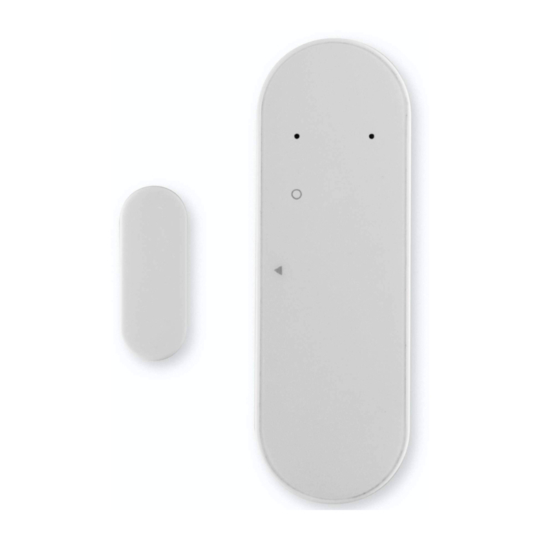
Bentel Security AMC10 User manual

AMC10
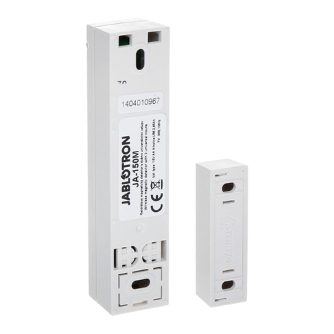
MINI DOOR / WINDOW CONTACT
CONTATTO MAGNETICO VIA RADIO
CONTACT MAGNETIQUE
GG
GG
G ENGLISH
ISTISBLVAMC10 0.0 260404 P7.0
REMOVE COVER
At the notched location 2 on the cover, insert the flat blade of a small screw-driver between the base and the cover
and twist the screwdriver to pop the cover off.
INSTALL BATTERY
Use care when installing the battery and observe the correct polarity (see Fig. 1). Use only an Eveready ithium Energizer
No. E 123AP or
Teckcell CR123A battery.
!!
!!
!WARNING! The Battery may explode f m streated. Do not recharge, d sassemble or d spose of n f re.
+The warranty does not apply to the battery of the Magnetic contact.
Select the location where the transmitter is to be mounted. Perform the
Module Placement Test to ensure that the selected location is in range of the wireless receiver (see receiver Installation
Manual for instructions).
REMOVE CIRCUIT BOARD
Before mounting the unit, remove the circuit board. At the notched location on the base which is on the same side as
the reed switch, insert the blade of a small screwdriver between the base wall and the bottom of the circuit board and
pry the circuit board up.
!!
!!
!Do not touch the co ls 4 on the c rcu t board as th s may damage the un t.
Mount the backplate of the transmitter using the screws 8 provided and replace the circuit board. The head of the
screw must be below the circuit board so that the sensor is not shorted out.
!!
!!
!Use flat-headed screws only.
Close the Magnetic Contact
+Use silicone to secure the Cover to the base, in order to avoid unintentional opening.
Mount the magnet no more than ¼" from the transmitter. Use the spacers provided. Once the unit and magnet are
mounted, open and close the window/door to ensure that none of the parts interfere with this movement.
+Only one magnet can be used per transmitter.
USING EXTERNAL CONTACTS
The external contact terminals 5 can be used to connect external contacts or other switches/ devices to the universal
transmitter. Install the additional device as per the manufacturer's instruction. Connect the device to the contact
terminals of the AMC10. The input is normally closed and is not supervised.
+The resistance of the wires used for the connection of the external contact to the auxiliary input must not exceed1
Ohm. Only one contact can be used. If an external contact is used, do not install the magnet.
!Use of the auxiliary input will void the IMQ-
SECURITY SYSTEM Certification.
TAMPER SWITCH
There is one tamper switch (3) on the AMC10 board.
Removing the cover will cause a zone tamper.
ENROLLING A AMC10
On the back of the door contact housing, there will
be two serial numbers, a five digit and six digit.
Please refer to your receiver Installation Manual for
information on which serial number should be enrolled.
AB
LITHIUM
CR123A
3V
1
3
4
6
5
18 2
7
8
9
10
11
12
13
14
17
16
8
9
10
15
13
N. DESCRIZIONE
1 Coperchio del Contatto
2 Riferimento per l'apertura
del Contatto
3 Pulsante Antisabotaggio
4 Antenna
5 Ingresso Ausiliario
6 Ampolla reed
7 Riferimento per la
rimozione della Scheda
8 Viti (2) per il fissaggio del
Contatto
9
Aperture (4) per i fili
canalizzati a vista o
sottotraccia
1 Fori (2) per il fissaggio del
Contatto
11 Distanziatore del Magnete
12 Magnete
13 Viti (2) per il fissaggio del
Magnete
14 Coperchio del Magnete
15 Fondo del Contatto
16 Alloggiamento Batteria
17 Scheda del Contatto
18 Batteria
No. DESCRIPTION
1 Contact Cover
2 Notch
3 Tamper button
4 Antenna
5 Auxiliary Input
6 Reed switch
7 PCB lever point
8 Contact screws (2)
9 Wire entries (4)
1 Contact screwlocations (2)
11 Magnet spacers
12 Magnet
13 Magnet screws (2)
14 Magnet Cover
15 Contact base
16 Battery housing
17 Contact board
18 Battery
TECHNICAL SPECIFICATIONS
Power Supply
1 x 3V ithium battery:
Energizer E 123AP, Tekell CR123A,
Panasonic CR123A, or similar
Operating Temperature 5 ÷ 40 °C
Performance evel I
Size (W x H x D) 88 x 31 x 30 mm
Weight (with battery) 58 g
N. DESCRIPTION
1 Couvercle du contact
2 Encoche
3 Autoprotection
4 Antenne
5 Entrée Externe
6 Ampoule Reed
7 Point de levier
8 Vis pour le contact (2)
9 Passage de câble (4)
1 Trous de fixation (2)
11 Cales pour l'aimant
12 Aimant
13 Vis pour l'aimant (2)
14 Couvercle de l'aimant
15 Embase
16 Support de Pile
17 Carte
18 Pile
Hereby, Bentel Security, declares that this device is in compliance with the
essential requirements and other relevant provisions of Directive 1999/5/
C.
The complete R&TTE Declaration of Conformity can be found at
www.bentelsecurity.com/dc.html.
II
II
I Fig. 1 Parti e Installazione del Contatto Magnetico
EE
EE
E Fig. 1 Parts and Installation of the Magnetic Contact
FF
FF
F Fig. 1 Contact Magnétique Radio
EE
EE
E - The Manufacturer reserves the right to change the technical
specifications of this product without prior notice.
II
II
I - Le specifiche tecniche del prodotto possono subire variazioni
senza preavviso.
FF
FF
F - BENTEL SECU ITY srl se réserve le droit de modifier les
spécifications techniques de ce produit sans préavis.

APERTURA
Per aprire il Contatto Magnetico, inserire un giravite a taglio nella tacca 2, tra il fondo ed il coperchio, e fare leva.
INSTALLAZIONE DELLA BATTERIA
Fare attenzione quando si installa la batteria ed osservare le giuste polarità (vedere Fig. 1). Usare soltanto una batteria
al litio da 3 V tipo Energizer E 123AP, Tekell CR123A, Panasonic CR123A, o equivalenti.
!!
!!
!La sost tuz one della batter a deve essere fatta soltanto da personale qual f cato; non r car care o apr re la
batter a: PUÓ ESPLODERE.
+La batteria a corredo del Contatto Magnetico è da considerarsi materiale di consumo e, quindi, esclusa dalla garanzia.
Scelto il posto e fissato il Contatto Magnetico, eseguire il Test d pos z onamento per assicurarsi che la posizione
scelta sia nel raggio d’azione del Ricevitore (leggere le istruzioni della centrale). Posizionare quindi il Magnete che deve
essere allineato con la parte terminale del Contatto Magnetico in modo da azionare l’ampolla Reed.
RIMOZIONE DELLA SCHEDA ELETTRONICA
Prima di montare il Contatto Magnetico, rimuovere la Scheda Elettronica dal Fondo usando un giravite a taglio: inserirlo
nella tacca 7, vicino all’ampolla Reed, e fare leva tra il Fondo e la Scheda Elettronica.
!!
!!
!Non toccare l’antenna 4, po ché s può dannegg are l Contatto Magnet co.
Fissare il Fondo del Contatto Magnetico usando le viti in dotazione (8), poi riposizionare la Scheda Elettronica sul
Fondo.
!!
!!
!Usare soltanto v t a testa p atta n modo che s ano d stant dalla Scheda Elettron ca, per non provocare
cortoc rcu t .
Chiudere il Contatto Magnetico
+Usare del silicone per il fissaggio del Coperchio al Fondo, in modo da evitare aperture accidentali.
Fissare il magnete ad una distanza non superiore a 6,4 mm dal trasmettitore usando il distanziatore previsto. Una
volta montati tramettitore e magnete aprire e chiudere la porta e/o la finestra per assicurasi che nessuna parte sia
in interferenza meccanica.
+Usare un solo Magnete per ogni Contatto Magnetico.
INGRESSO AUSILIARIO
Sulla morsettiera 5 è presente un Ingresso Ausiliario che può essere usato per il collegamento di un contatto esterno
al Contatto Magnetico: installare il dispositivo supplementare in base alle istruzioni del costruttore. ’Ingresso
Ausiliario è normalmente chiuso e NON è supervisionato.
+La resistenza del filo usato per il collegamento del contatto esterno all’Ingresso Ausiliario NON deve essere superiore
a 1 Ohm.
Può essere usato un solo contatto.
Se un contatto esterno viene collegato all’Ingresso Ausiliario, NON installare il Magnete.
!Al fine di garantire la certificazione IMQ-SISTEMI DI SICUREZZA, l’ingresso ausiliario NON deve essere utilizzato.
ANTISABOTAGGIO
Sulla Scheda Elettronica del Contatto Magnetico è
presente un Pulsante Antisabotaggio (3): la rimozio-
ne del Coperchio provocherà un Sabotaggio di Zona.
CONFIGURAZIONE
Nella parte posteriore del Contatto Magnetico sono
presenti due numeri di serie: uno di cinque cifre e
l’altro di sei. eggere le istruzioni della centrale per
sapere quale numero di serie deve essere usato per
la Configurazione del Contatto Magnetico. Con la presente, Bentel Security dichiara che questo prodotto è conforme
ai requisiti essenziali ed alle altre disposizioni pertinenti stabilite dalla
direttiva 1999/5/C .
La Dichiarazione di Conformità completa pu essere trovata
all’indirizzo www.bentelsecurity.com/dc.html.
II
II
I ITALIANO FF
FF
F FRANÇAIS
CARATTERISTICHE TECNICHE
A limentazione
1 batteria al litio da 3 V:
Energizer E 123AP, Tekell CR123A,
Panasonic CR123A, o equivalente
Temperatura
di Funzionamento 5 ÷ 40 °C
ivello di Prestazione I
Dimensioni ( x A x P) 88 x 31 x 30 mm
Peso (con batteria) 58 g
Par la présente, Bentel Security, declare que le produit est conforme avec
l’essentiel des Recommandations de la Directive 1999/5/C .
La Déclaration complête de conformité R&TTE peut être obtenue
sur:
www.bentelsecurity.com/dc.html.
SPECIFICATIONS TECHNIQUES
Alimentation
1 x 3V Pile ithium:
Energizer E 123AP, Tekell CR123A,
Panasonic CR123A, ou similaire
Temperature de fct 5 ÷ 40 °C
Niveau de rendement I
Taille ( x H x l) 88 x 31 x 30 mm
Poids (avec pile) 58 g
OUVRIR LE COUVERCLE
Introduire un tournevis plat dans l’encoche 2 (figure 1), et faire levier pour séparer l’embasse de son couvercle.
INSTALLER LA PILE
Bien respecter la polarité de la pile (voir Fig. 1). Utiliser seulement une Eveready ithium Energizer No. E 123AP ou une
pile Teckcell CR123A.
!!
!!
!ATTENTION! La P le poura t exploser s elle est maltra tée. Ne pas recharger, désassembler ou mettre au feu.
+La garantie ne s’applique pas à la pile du contact magnétique.
Selectionner le lieu ou sera installer le contact. Faire un Test de portée pour vous assurer que vous vous trouvez dans
une zone reçue par le recepteur (voir page 10 du manuel de prog par clavier).
DEMONTER LE CARTE ELECTRONIQUE
Avant de fixer le contact, demonter la carte .utiliser un tournevis plat pour faire levier au niveau du support noir de la
pile.
!!
!!
!Ne pas toucher à l’antenne 4, au r sque de l’endommager.
Fixer l’embasse du contact à l’aide des vis 8 et replacer la carte. es têtes de vis ne doivent pas toucher la carte,
ceci afin d’éviter un court circuit.
!!
!!
!Ut l ser des v s à tête plate seulement.
Fermer le contact magnétique.
+Vous pouvez utiliser du silicone pour éviter une éventuelle ouverture.
’espace maximun entre l’émetteur et l’aimant doit être de 6mm. Utiliser les cales si nécessaire. orsque les deux
parties sont fixées, ouvrir et fermer la porte/fenêtre pour vous assurer que rien n’entrave le mouvement.
+Utiliser seulement 1 aimant par contact.
UTILISATION DE CONTACTS EXTERNE
e bornier 5 permet de connecter des contacts externes ou autres système de détection en utilisant l’ AMC10
comme emetteur universel. Installer le système de détection comme indiqué dans la notice du fabricant. Connecter
le detecteur sur le bornier 5 de l’ AMC10. Cette entrée est de type NF et n’est pas supervisée.
+La resistance du câble connecté sur le bornier 5 ne doit pas excéder 1 Ohms.
Si le bornier 5 est utilisé, ne pas installer l’aimant du AMC10.
! Utiliser l’entrée 5 est dépourvue de certification IMQ-SECURITY SYSTEM.
AUTOPROTECTION SABOTAGE
Il y a une autoprotection (3) sur la carte du AMC10. Ouvrir le boitier provoquera une alarme Sabotage.
ENROLLER AMC10
Sous l’embasse du contact, sont imprimés 2 numéros de série, de 5 digits et 6 digits. Relever le numéro ESN et
reporter au manuel d’installation de la centrale.
Other Bentel Security Security Sensor manuals

Bentel Security
Bentel Security Visus99 User manual
Bentel Security
Bentel Security RAY60 User manual
Bentel Security
Bentel Security BMD503 User manual
Bentel Security
Bentel Security FC400H User manual

Bentel Security
Bentel Security ZT100H User manual
Bentel Security
Bentel Security RAY60-S User manual
Bentel Security
Bentel Security BW-MCN User manual
Bentel Security
Bentel Security DT800 User manual
Bentel Security
Bentel Security FC450IB User manual
Bentel Security
Bentel Security DT800 User manual
