WHALETEQ SECG 5.0 AIO User manual

SECG 5.0 AIO | User Manual
WHALETEQ
Single Channel ECG Test System
(SECG 5.0 AIO)
User Manual
Version 2020-12-31
Software Version 1.1.22.9

Page 2 of 34
SECG 5.0 AIO | User Manual
Contents
1 Introduction .............................................................................................. 4
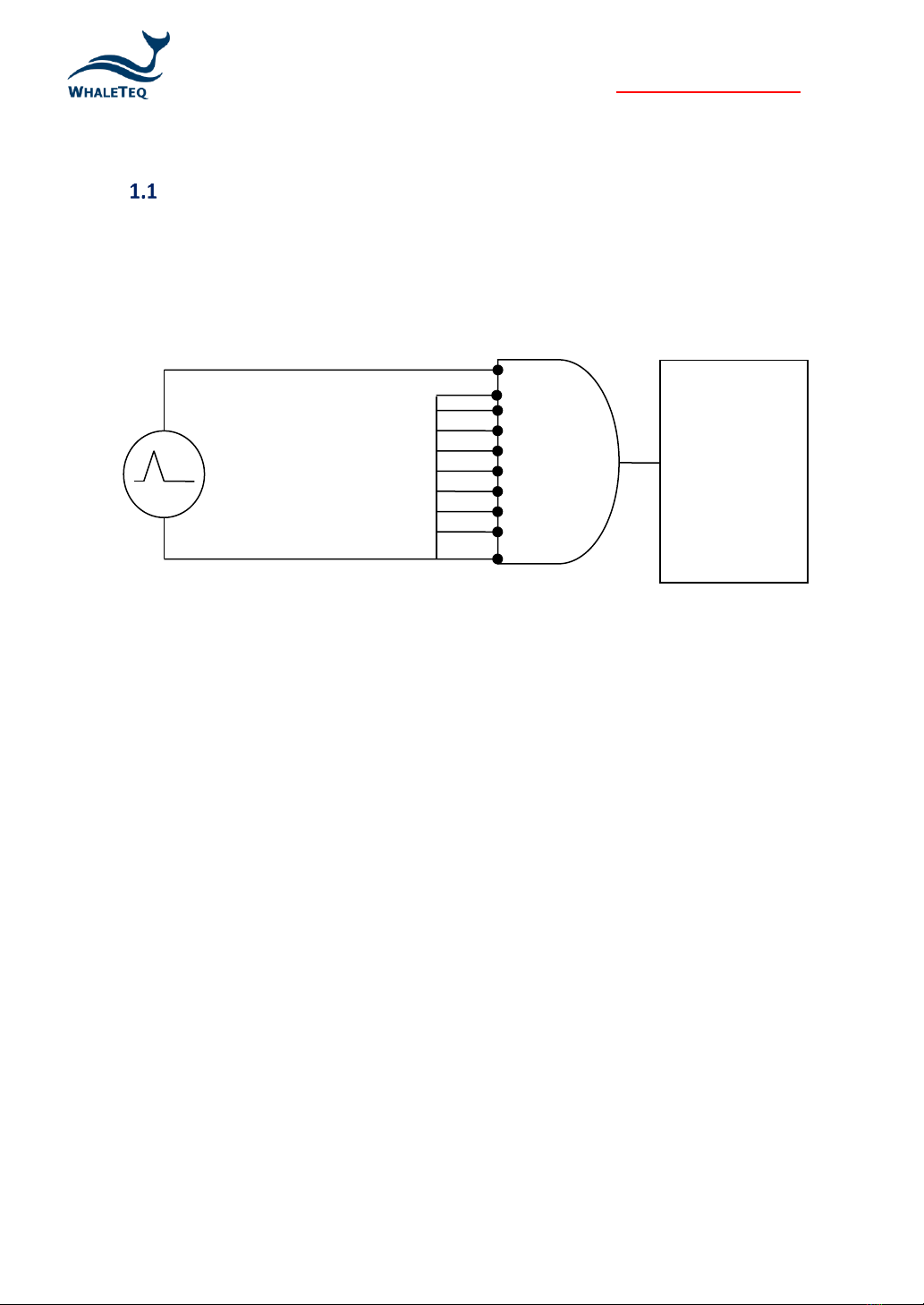
Basic concept ........................................................................................................ 4
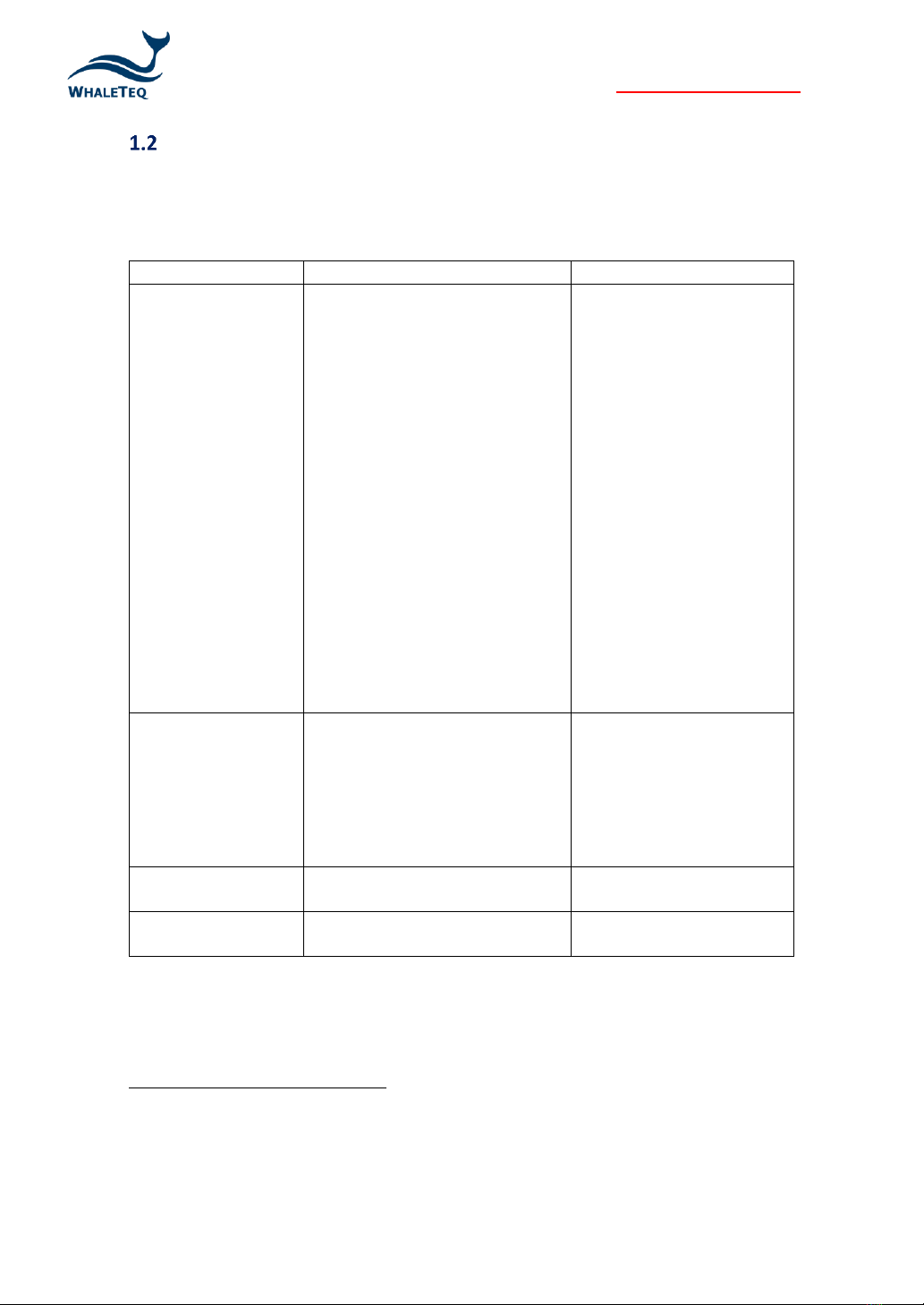
Standard/Application ............................................................................................ 5
SECG 5.0 AIO Overview of ECG Module ................................................................ 6
I/O Interface Overview.......................................................................................... 6
Main Specifications ............................................................................................... 7
Product Label ........................................................................................................ 8
Pollution Degree ................................................................................................... 9
Cleaning method ................................................................................................... 9
2 Set Up ......................................................................................................10
Software Installation........................................................................................... 10
2.1.1 System Requirements...................................................................................................10
2.1.2 SECG 5.0 AIO PC Software Installation..........................................................................10
2.1.3 First Time Using WhaleTeq Product –USB Driver Installation......................................11
2.1.4 First Time Using WhaleTeq Product –Microsoft .Net Framework 4.0 Installation.......11
Connecting to the ECG ........................................................................................ 12
Set up a Low-noise Test Environment.................................................................12
Software Update .................................................................................................12
Main Screen ........................................................................................................ 13
Description of Functional Groups ....................................................................... 14
2.6.1 Signal Parameters.........................................................................................................14
2.6.2 Signal add-on ................................................................................................................17
2.6.3 Output Lead Electrode..................................................................................................20
2.6.4 Output Summary ..........................................................................................................20
2.6.5 Output Waveform Display............................................................................................20
2.6.6 Play/Stop Button ..........................................................................................................21
Special Functions.................................................................................................21
2.7.1 Standard Waveforms....................................................................................................21
2.7.2 File Replay.....................................................................................................................21
2.7.3 NST Noise...................................................................................................................... 23
2.7.4 Auto ..............................................................................................................................24
2.7.5 Lead OFF .......................................................................................................................26
2.7.6 Auto Sequence..............................................................................................................26
Language Selection ............................................................................................. 27
Standard Assistant .............................................................................................. 27
2.9.1 Active SECG standard assistant.....................................................................................28
2.9.2 Standard Assistant Software.........................................................................................28
3 Testing to IEC and AAMI Standards ...........................................................31

Page 3 of 34
SECG 5.0 AIO | User Manual
Relation between IEC figures and WhaleTeq SECG 5.0 AIO................................ 31
Terminals of P1, P2 and P6.................................................................................. 32
4 Software Development Kit (SDK)...............................................................32
5 Calibration and Validation ........................................................................32
6 Trouble Shooting ......................................................................................33
7 Caution ....................................................................................................33
8 Ordering Information................................................................................33
Standard accessories........................................................................................... 33
Optional Software and Accessories..................................................................... 34
9 Version information..................................................................................34
10 Contact WhaleTeq ....................................................................................34

Page 4 of 34
SECG 5.0 AIO | User Manual
1 Introduction
Basic concept
The WhaleTeq Single Channel ECG Test System 5.0 (SECG 5.0 AIO) provides a single
waveform to one or more lead electrodes of diagnostic, ambulatory or monitoring ECGs, for
testing to IEC/YY/JJG particular standards. The following diagram shows the single channel
concept:
(Figure 1) Single Channel Concept
Via a SECG 5.0 AIO, the system produces voltage up to 40 mVpp. The SECG 5.0 AIO contains
resistor/capacitor networks, dc offset, pacing circuit and relay switching to provide the full
range of single channel performance tests in IEC/YY/JJG standards.
The basic range of tests in the standards include, for example:
- Sensitivity (accuracy of the mV/mm indication)
- Frequency response (sine wave, and impulse tests)
- Input impedance
- Noise
- Multichannel cross talk
- Accuracy of heart rate indication
- Pacemaker rejection
- Tall T-wave rejection
For a full list of tests, refer to the standard together with Section 1.2.
The system does not provide:
- CMRR tests (this requires a special low-noise test equipment, please to CMRRseries
test systems on WhaleTeq website)
- Multichannel waveforms, such as the CSE, AHA, MIT databases (this requires a
multichannel system, please refer to MECG 2.0 on WhaleTeq website)
RA
LA
LL
RL
V1
V2
V3
V4
V5
V6
ECG
Device Under Test

Page 5 of 34
SECG 5.0 AIO | User Manual
Standard/Application
The following table shows the standards for which SECG 5.0 AIO has been designed for, and
includes any limitations:
Standard
Clause(s)
Limitations/Notes
IEC 60601-2-25:2011
(Diagnostic)
201.12.4: All performance tests
except:
◆CMRR test and baseline
noise
➔use WhaleTeq CMRR
series tester
◆Test referring to the CTS
atlas (CAL/ANE
waveforms)*, CSE database
➔use WhaleTeq MECG
series tester
*Note: for most tests CAL/ANE
waveforms are alternates. For
two tests may be required
(201.12.4.102.3, test of lead
networks; and 201.12.4.105.3
test of ringing from mains notch
filter)
For 201.12.4.101 (large dc
offset test), the SECG is
limited to ±1Vdc. However,
this is almost certainly
enough to exceed the point
of saturation.
For the test circuit in figure
201.110, switch position A is
not provided. This is
considered an error in the
standard due to the loading
effect of R2. Instead the DC
offset is provided in series
with output as per Figure
201.106.
IEC 60601-2-27:2011
(Patient monitoring)
201.7.9.2.9.101 b), 4) and 6)
(special test waveforms for Figure
201.101)
201.12.1.101, all performance
tests except baseline noise and
CMRR tests
No known limitations
IEC 60601-2-47:2012
(Ambulatory)
201.12.4, all tests except CMRR
test
No known limitations
ANSI/AAMI EC 13
2002/(R)2007/C2008
All performance tests except
CMRR test and as noted right
See below for Clauses 5.1.4
n) and 5.2.9.1 f), g) 1
General limitation: this equipment is designed for use with isolated ECG circuits, as are
generally provided for medical ECG. If applied to a non-isolated circuit, the noise may be
excessive.
1
5.1.4 n) Fast QRS: The sampling rate is limited to 0.2ms, some distortion of the pulse is possible below
6ms.
5. 2.9.1 f), g): Functionality is not included at this time; note the test is not applicable to most ECG
systems

Page 6 of 34
SECG 5.0 AIO | User Manual
SECG 5.0 AIO Overview of ECG Module
I/O Interface Overview
1. Power Connector
2. RCA1 Monitor x 1: To monitor the actual signal output. (1mV = 1mV output)
RCA2 Monitor x 250: To monitor the applied signal. (1mV = 250mV output)
3. USB Type B receptacle connector: To connect with PC and allow PC software to control
SECG 5.0 AIO. Before operating PC software mode, it requires to switch to PC (left side
of DIP SWITCH) and an additional description “SIMULATION MODE” will be shown on
the title bar of touch screen.

Page 7 of 34
SECG 5.0 AIO | User Manual
4. Reserved output port
5. HDMI output port :When connecting to the external display device via HDMI
interface, please do connect a mouse via USB type A connector for the normal
operation.
6. USB Type A receptable connector: To connect with flash disk or mouse
7. Network connection port
Main Specifications
In general, the system has been designed to the standards above, taking into account Clause
201.5.4 in IEC 60601-2-25 and IEC 60601-2-27. Below includes these parameters and also
other system parameters necessary for testing. For reference the system capability is
provided.
Parameter
Specification
System Capability /
Notes
Main output voltage
accuracy
±1% for amplitudes of
0.5mVpp or higher
±0.3%
Main output voltage
resolution
(DAC resolution)
N/A
2.5µV
Frequency / pulse repetition
rate accuracy
±1%
±0.1%
Pulse duration / timing
accuracy (excluding pacing)
±1ms
±0.2ms
Pacing pulse width accuracy
±5µs
±1µs
Pacing pulse amplitude
accuracy, range
±2mV pulse: ±1%
>2mV pulse: ±10%
Range: ±2mV to ±700mV
±2mV pulse: ±0.3%
100mV pulse: ±1% or ±5mV
Pacing pulse characteristics
Rise/fall time 5µs
Overshoot <1%
Settling time <1%
Pacing pulse overshoot
(intentional)
Method A according to IEC
60601-2-27
Resistor tolerance
±1%
±0.5%
Capacitor tolerance
±5%
±5%
Precision 250:1 divider
±0.1%
±0.05%
Sample rate
5kHz ± 0.1%
10kHz ± 0.05% (50ppm)
DC offset (fixed, noise free,
sourced from internal super
capacitor)
300mV ± 1%
300mV ±0.1%
DC offset (variable, up to
1000mV, may include up to
50µVpp noise)
Setting ±1% or ±3mV
Setting ±1% or ±3mV

Page 8 of 34
SECG 5.0 AIO | User Manual
Environment
15 ~ 30°C (by design)
30 ~ 80% RH (by design)
5〜40℃
50〜80%RH
altitude < 2000M
Overvoltage CAT II
Size(L x W x H)
Weight
-
27X16X22 CM
3.5 KG
Power Supplier
-
Input: 100-240Vac 1.5A
50~60Hz
Output : 12V,3.33A
Power cable Note
-
SVT/ 18AWG/300V/105 ℃
or
H05VV-F / 0.75mm2 /
300V/105 ℃
Length 3m MAX
Note: Use the power cord with the plug style that matches the power socket where the
equipment is located and the compatible power cord corresponds to the AC voltage of the
power outlet and has been approved by, and complies with, the safety standards in the
country of purchase.
Product Label
Separate equipment from other waste. The equipment that needs to be
recycled includes: host, wire, power supply
Warning, please refer to the manual
Product serial number 2D Barcode

Page 9 of 34
SECG 5.0 AIO | User Manual
Pollution Degree
Pollution measurement for the surrounding environment and inside the product. Generally,
the internal environment of a product is considered the same as its external environment.
This product is only suitable for the evaluated environment.
Pollution Degree 1: No pollution or only dry, nonconductive pollution occurs. The pollution
has no effect.
Pollution Degree 2: Normally only nonconductive pollution occurs. Temporary conductivity
caused by condensation is to be expected.
Pollution Degree 3: Conductive pollution or dry nonconductive pollution that becomes
conductive due to condensation occurs. To be found in industrial environment or
construction sites (harsh environments).
Pollution Degree 4: The pollution generates persistent conductivity caused by conductive
dust, rain, or snow.
Pollution degree
Pollution degree 2 (as defined in IEC 61010-1). The evaluation is limited to indoor and dry
environments.
Cleaning method
Please keep the surface of the product clean and dry. Please remove the input signal before
cleaning the product. Please check the instrument frequently as required by the operating
conditions. To clean the external surface, follow these steps:
1. Use a lint-free cloth to wipe the dust on the outside of the instrument. Pay attention to
avoid scratching the display filter made of plastic.
2. Use a soft cloth dampened with water to clean the instrument. The cleaning effect is
better with 75% isopropyl alcohol aqueous solution.
Note.
When cleaning the exterior, avoid wetting the inside of the device. Only moisten a dry cloth
or cotton swab with an appropriate amount of cleaning solution. To avoid damage to the
instrument, please do not expose it to various sprays, liquids or solvents, and do not use any
corrosive or chemical cleaning products.

Page 10 of 34
SECG 5.0 AIO | User Manual
2 Set Up
Software Installation
2.1.1 System Requirements
The single channel ECG system SECG 5.0 AIO can be operated via the touch screen or PC
software via USB connection
PC Requirements:
-Windows PC (Windows 7 or later, suggest to use the genuine version)
-Microsoft .NET 4.0 or higher
-Administrator access (essential for installing software, driver, and Microsoft .Net
Framework)
-1.5 GHz CPU or higher
-1GB RAM or higher
-USB port
2.1.2 SECG 5.0 AIO PC Software Installation
Please follow the below steps to download and execute SECG Software.
․Download SECG 5.0 software from WhaleTeq website
․Open the file explorer and select to the download location
․Extract the file to your assigned folder
․Open the destination folder and make sure the all files are unzipped in the same folder
․Double click on SingleChannelECG5.0.exe to execute SECG 5.0 AIO PC software
If SECG software can’t be executed properly or this is the first time using
WhaleTeq product, please refer to below two sections (2.1.3 and 2.1.4) to confirm that USB
driver and Microsoft .Net Framework 4.0 are all installed.

Page 11 of 34
SECG 5.0 AIO | User Manual
2.1.3 First Time Using WhaleTeq Product –USB Driver Installation
Microsoft Windows 10
As Windows 10 has built-in Microchip® USB Driver, there’re no needs to install any drivers.
It just takes a while for Windows Device manager to recognize and install the driver.
If Windows device manager can’t recognize WhaleTeq product, please follow the below
instructions to Install Microchip® USB driver.
Microsoft Windows 8 and Windows 8.1
․Windows 8 and Windows 8.1 can’t recognize SECG unit, please download “mchpcdc.inf”
from WhaleTeq website. This driver is provided by Microchip® for using with PIC
microprocessors having built-in USB function.
․As mchpcdc.inf provided by Microchip® does not contain digital signature, please
disable driver signature enforcement in Windows 8 and Windows 8.1. Please click here
to watch the tutorial video.
․When the USB module is connected for the first time, select manual installation, and
point to the folder containing the above file. Then continue to follow the instructions
to finish the installation. There may be a warning that the driver is not recognized by
Windows®, and this can be ignored. Please click here to watch the tutorial video.
Microsoft Windows 7
․Windows 7 can’t recognize SECG unit, please download “mchpcdc.inf” from WhaleTeq
website. This driver is provided by Microchip® for using with PIC microprocessors
having built-in USB function.
․When the USB module is connected for the first time, select manual installation, and
point to the folder containing the above file. Then continue to follow the instructions
to finish the installation. There may be a warning that the driver is not recognized by
Windows®, and this can be ignored. Please click here to watch the tutorial video.
2.1.4 First Time Using WhaleTeq Product –Microsoft .Net Framework 4.0
Installation
WhaleTeq software is developed by Microsoft .Net Framework 4.0. If SECG software fails to
launch properly, please check whether Microsoft .Net Framework 4.0 or higher versions was
installed in the operation system.
If your PC does not install Microsoft .Net Framework 4.0 or higher versions, please download
from Microsoft website. Please click here to watch the tutorial video (from 2:03).

Page 12 of 34
SECG 5.0 AIO | User Manual
Connecting to the ECG
For connecting the ECG device easily, SECG 5.0 AIO is equipped with 12 electrode terminals
sockets:
1. RL1, RL2 ~ V6 terminals: Total 11 terminals. RL1 and RL2 are connected
together, corresponding to the 10 electrode leads of 12-lead ECG (or fewer
lead channel ECG)
2. GND terminal: This terminal is connected to ground
Set up a Low-noise Test Environment
A noise free environment is necessary for testing ECG equipment. This can be achieved
relatively easily by (a) using a metal bench or metal sheet underneath the ECG device under
test and the WhaleTeq SECG test unit, and (b) connecting SECG 5.0 AIO GND terminal to the
sheet and also the frame ground (or EP terminal) of the ECG device under test:
With this set up, turn the ECG device under test to maximum sensitivity, turn off the ac filters
(if possible) and confirm that the level of noise is acceptable for tests. For most tests, this set
up is satisfactory without any special efforts. However, for the input impedance test with the
620kΩ is in series the imbalance in impedance can cause high noise. For this test, the ac filter
may be turned on. If the noise is still excessive, move to an electrically quiet environment or
increase the size of the metal sheet underneath and around the set up.
Software Update
You can download the latest software from WhaleTeq website. If you cannot update your
SECG 5.0 AIO software, please contact WhaleTeq service team (s[email protected]m).
ECG Device
Under Test
Frame ground
or EP terminal
Metal-bench, metal sheet or foil
Lead Wires Connection

Page 13 of 34
SECG 5.0 AIO | User Manual
Below is the instruction for updating to the latest software:
Download the latest software from WhaleTeq website. Extract the zip file to a USB flash disk
and make sure this APK file is in the root directory. Once you plug this USB flash disk into
SECG 5.0 AIO, a notification window shall prompt to update to the latest software. Press
install to complete the process.
Main Screen

Page 14 of 34
SECG 5.0 AIO | User Manual
01-Select waveform signal types and parameters
02-Select add-on signals (DC offset, pacing, noise….)
03-Select the output lead electrode
04-Detailed parameters of output waveform
05-The real time display of output waveform
06-Function tap (Waveform, Special Function and Assistant)
07-Click to play the waveform with preset parameters and options
Description of Functional Groups
2.6.1 Signal Parameters
Signal Type
Select the types of output waveform. Please refer to Table.1 for details.
Frequency
The frequency can be set in either Hz or beats per minute (BPM). Changing one will
automatically change the other to match. For pulse waveforms (rectangle, triangle, ECG), the
frequency can also be referred to as the pulse repetition rate, or heart rate. For some pulse
settings the frequency is limited to prevent overlapping pulses.
Amplitude
Adjusts the waveform amplitude from 0 to 20mV at a 0.01mV resolution. For all waveforms
the amplitude represents the peak to peak value. For example, for a 1mV sine wave the
actual waveform varies between +0.5mV and -0.5mV. This correlates with testing
requirements in standards.
Pulse Width
Applies to rectangle, triangle and exponential
pulse waveforms only. For the rectangle, pulse
width is defined as the time between crossing
the 50% point in rising and falling edges of the
pulse
2
. For triangle pulses, the setting matches
the base of the triangle pulse. For exponential
pulse, the set pulse width is time constant. Pulse
width can be set to down to 2ms.
2
To minimise ringing due to ECG notch filters, rectangle pulses have a rise time of 1ms. This means that
a 20ms rectangle pulse will actually have a 21ms base and a 19ms at the top of the pulse. This definition
ensures that the pulse integral matches the setting, e.g. a 3mV 100ms pulse will have an integral of
300µVs.

Page 15 of 34
SECG 5.0 AIO | User Manual
ECG Waveform Parameters
P Amplitude: 0~2mV; P Duration: 50~100ms; PR Interval: 10~200ms
QRS Duration: QRS duration range of ECG waveform is 10~200ms, matching the
requirements of the standard.
ST Deviation:-1~1mV; QT Interval:current QRS value~900ms
T Duration:Allows setting of the amplitude of the T-Wave in ECG waveforms, to verify tall
T-wave rejection ability of patient monitors according to IEC 60601-2-27. Maximum
amplitude is 5mV. For the heart rate accuracy test in IEC 60601-2-27, a T-wave component
is not required. In this case, set the T-wave to zero.
As IEC60601-2-27 requires a special waveform, please turn on the option of “IEC 60601-2-
27 ECG waveform” before testing.

Page 16 of 34
SECG 5.0 AIO | User Manual
Waveform
Description
Waveform Example
Sine
Parameters are
amplitude (mVpp) and
frequency (Hz or BPM)
Triangle
Parameters are
amplitude (mVpp) and
frequency (Hz or BPM)
Square
Parameters are
amplitude (mVpp) and
frequency (Hz or BPM)
Rectangle
pulse
Parameters are
amplitude (mVpp), pulse
width (ms) and frequency
(Hz or BPM)
Triangle
pulse
Parameters are
amplitude (mVpp), pulse
width (ms) and frequency
(Hz or BPM)
Exponential
Parameters are
amplitude (mVpp), pulse
width (ms) and frequency
(Hz or BPM)
ECG
This waveform is based
on IEC60601-2-27(Figure
201.110 and 201.113).
Parameters are
amplitude (mVpp) and
frequency (Hz or BPM),
QRS interval and T wave
amplitude
Table 1. Waveform types in testing

Page 17 of 34
SECG 5.0 AIO | User Manual
2.6.2 Signal add-on
DC Offset
This function allows the operator to switch in a dc offset. The maximum voltage is 1000mV.
In the condition of setting DC offset to 300mV, the DC offset is sourced from an internal
“super capacitor” which at least 3 minutes of accurate and stable 300mVdc offset to be
placed in series with the main waveform, without impacting the quality of that main
waveform.
Pacing Waveform Parameters

Page 18 of 34
SECG 5.0 AIO | User Manual
In general, a pacemaker pulse can be added to any main function (sine/triangle/ECG etc.).
Please refer to Table 2 for the pacing parameters.
Pacing Amplitude
This can be set in steps of 2 ranging from -700 to +700mV
When set to zero the pacing function is turned off regardless
of other pacemaker settings.
When set at +2 or -2mV the pacing pulse, the accuracy is
better than ±1%. For settings above 2mV, the design accuracy
is ±1% or ±5mV.
Pacing Duration
Can be set between 0.1 and 3.0ms, covering the range
required by all standards.
Overshoot Time
Constant
Settings from 2ms to 100ms, creates an overshoot according
to Method A of IEC 60601-2-27 (0.25 of the pacing amplitude
or 2mV, whichever is smaller).
Pacing rate/
synchronized with main
function
If the “Synchronized with main function” checkbox is ticked,
the pacing pulse will be synchronized with the main function,
such as the ECG waveform in IEC 60601-2-27.
If this box is not ticked, the user can set the pacing rate
independent of the main function (e.g. 80 bpm as required by
IEC 60601-2-27, 100bpm according to IEC 60601-2-51).
Single / Double pulses,
150ms and 250ms
advanced
This group selects whether single or double pulses are
required according to IEC 60601-2-27. If double pulses are
required, they can be 150 or 250ms advanced.
Table 2. Pacing Parameters
Noise
Superimpose 50Hz/60Hz/white noise to output signal with adjustable amplitude voltage.

Page 19 of 34
SECG 5.0 AIO | User Manual
ECG Special Add-on Parameters
AAMI EC 13 Drift Test:
(ECG 2-27 waveform only): when checked adds 4mVpp 0.1Hz triangle waveform to the ECG
signal (for testing baseline drift).
Respiration:
Provide resistant method and wave modulation method to simulate the change during
human breathing. The system is able to adjust respiration rate, ratio and apnea time.
Resistant Method
To simulate the changes of human breathing via variable resistance. The change is based on
a basic resistance level with variations. Frequency of resistance variation is the same as the
preset respiration frequency.
Wave Modulation Method
Baseline→Simulate the human breathing changes via baseline changes of ECG waveform.
Amplitude→Simulate the human breathing changes via the amplitude of ECG R wave.
Frequency→Simulate the human breathing changes via ECG heart rate frequency.
Apena Time: SECG will output the testing signal for 1 minutes. The testing signal shall stop
after the preset apena time parameter and then repeat the sequence.

Page 20 of 34
SECG 5.0 AIO | User Manual
2.6.3 Output Lead Electrode
This section allows the user to select which lead electrode the output is connected to (e.g.
terminal P1 in the IEC 60601-2-25, Figure 201.106). Unselected electrodes are connected to
the system ground (terminal P2 in Figure 201.106).
More than one lead electrode may be selected. For example, if it is desired to have Lead I
and Lead II have a positive indication, LA and LL can be selected.
2.6.4 Output Summary
The output waveform and related settings shall display in this section. User can have a
better idea of the waveform details.
User can also click “Save as Script “to save the waveform settings as an individual file. The
script file can be loaded in the auto sequence function. Please refer to section 2.7.6 for
details.
2.6.5 Output Waveform Display
The output display provides an image similar to that provided by ECGs. The sensitivity of the
display range may be set at 5mm/mV, 10mm/mV or 20mm/mV to cover the full range of
waveforms offered by the system. The time rate is fixed.
The output display uses the same data as used in the DAC output and serves as a cross check
of the selected waveform, and also allows the user to view the original waveform as filters in
the ECG device under test can substantially alter the waveform. The pacing signal is shown in
red color.
Table of contents
Other WHALETEQ Test Equipment manuals

WHALETEQ
WHALETEQ DFS360 User manual

WHALETEQ
WHALETEQ CMRR 2.0 User manual

WHALETEQ
WHALETEQ CMRR 3.0E User manual

WHALETEQ
WHALETEQ WAIOT-N User manual

WHALETEQ
WHALETEQ DFS360 User manual

WHALETEQ
WHALETEQ DFS360 User manual

WHALETEQ
WHALETEQ HFPA150 User manual

WHALETEQ
WHALETEQ SECG 4.0 User manual

WHALETEQ
WHALETEQ AECG100 User manual

WHALETEQ
WHALETEQ SEEG 100E User manual
Popular Test Equipment manuals by other brands

LaserLiner
LaserLiner LR44 manual

Agilent Technologies
Agilent Technologies 35670A installation guide

Teledyne Lecroy
Teledyne Lecroy WavePro HD series Getting started guide

Meco
Meco PHT4545 user manual

Quantifi Photonics
Quantifi Photonics BERT 1005 Series user manual

Rohde & Schwarz
Rohde & Schwarz RTE1022 user manual