WHALETEQ CMRR 2.0 User manual

Common Mode Rejection Ratio Tester | User Manual
WHALETEQ
Common Mode Rejection Ratio Tester
(CMRR 2.0)
User Manual
(Revision 2020-09-03)

Common Mode Rejection Ratio Tester | User Manual
1
Contents
1
Introduction .........................................................................................................................2
2
Description...........................................................................................................................3
2.1
CMRR Box..............................................................................................................................................3
2.2
ECG Breakout Boxes..............................................................................................................................4
3
Set up................................................................................................................................... 5
3.1
Environment, noise reduction...............................................................................................................5
4
Calibration ...........................................................................................................................6
5
Principle of the CMRR test .................................................................................................... 9
5.1
Common mode rejection ratio explained .............................................................................................9
5.2
Common mode rejection in ECG equipment ........................................................................................ 9
5.3
Test equipment ...................................................................................................................................10
6
Operation........................................................................................................................... 12
7
Warnings/Cautions/Notes .................................................................................................. 14
8
Specifications ..................................................................................................................... 15
9
Contact details ................................................................................................................... 15

Common Mode Rejection Ratio Tester | User Manual
2
1
Introduction
WhaleTeq’s main focus is on tests in ECG standards is the Single Channel and Multichannel
ECG test systems. However, these systems do not cover common mode rejection ratio due to
the nature of test (double box construction, noise free environment). To meet this need,
WhaleTeq has developed a CMRR test box.
The box is uses the double shield construction according to various IEC standards (IEC 60601-2-
25, IEC 60601-2-27, IEC 60601-2-47, IEC 60601-2-51), and includes the following special
features:
-Switching is eliminated by having the imbalance impedance and dc offset available on a
special terminal on the CMRR ECG Breakout box. Although the diagram shown in
standards has all the switches open, for the actual test, only one switch is required to be
open at a time. Rather than switching in the imbalance, the user simply changes the
external electrode connections to the imbalance terminal. Elimination of these switches
greatly simplifies the design of the CMRR box.
-The box includes a step up transformer to allow a normal signal generator to be used.
The tests in IEC 60601-2-25: 2011, IEC 60601-2-27 and IEC 60601-2-51 require a
20Vrms supply, and most function generators are limited to 7Vrms. This feature can be
bypassed if desired by connecting directly to the blue (input monitor) 4mmsocket.
-The box includes a 1000:1 (50MΩ:50kΩ) voltage divider to allow monitoring of the
applied voltage. The standard requires that the unloaded voltage is adjusted to 10Vrms,
however, the source impedance is sufficiently high that it cannot be measured by normal
meters. A 1000:1 divider, constructed of 50MΩ:50kΩ and is permanently connected has
been found to be the best compromise between accuracy, circuit loading, noise and input
impedance of typical multimeters. Using this feature the adjusted voltage should be
10mVrms (or 1/1000 of the target voltage).
-The box includes a precision, stable ±300mV source as used in other WhaleTeq
equipment

Common Mode Rejection Ratio Tester | User Manual
3
2
Description
2.1
CMRR Box
The CMRR box internal construction as below, the only features not shown is the internal screen
(internal box), which is provided around the circuit floating at 10Vrms as shown by the blue
shading below:
For connecting the CMRR Box to test the ECG device, use the “ECG breakout box” provided, as
explained on the following page.
Alternately the ECG device under test can be directly connected to CMRR Box using a male D15
connector. The pin outs are:
The imbalance can be determined by external connections, simulating the ECG breakout boxes
on the following page.
01 - RA
06 - V2
11 - CMRR inner box
02 - LA
07 - V3
12 - DC offset (no impedance)
03 - LL
08 - V4
13 - DC offset (impedance)
04 - RL
09 - V5
05 - V1
10 - V6

Common Mode Rejection Ratio Tester | User Manual
4
2.2
ECG Breakout Boxes
The WhaleTeq CMRR 2.0 is supplied with two breakout box to suit different standards.
IEC 60601-2-25: 2011 (formerly IEC 60601-2-
51), IEC 60601-2-47: 2012 and IEC 60601-2-27
requires 9 leads (RA/RL/LL/V1 to V6) to be
shorted to inner box with only RL/N and
Imbalance (with DC) having the impedance of
51kΩ /47nF. To implement this, a special
breakout box is used which shorts 9 terminals to
the inner shield, except RL/N and Imbalance
with DC terminal:
The effective circuit is:
Imbalance
terminal
9 terminals
(RA, LA, LL, V1 ~ V6)
RL/N
47nF
The test circuit in IEC 60601-2-47: 2001 and
ANSI/AAMI EC 13 is the same except that all
lead electrodes have the 51k/47nF, except one
which is directly connected to the inner shield:
This has the effective circuit:
Imbalance
(with DC)
Other terminals
(RA, LA, LL, RL, V1 ~ V6)
Imbalance
(no DC)
CM voltage (10Vrms)
100pF
Each lead has
51kΩ//47nF
DC
offset
100pF
20Vrms
100pF
20Vrms
CM voltage (10Vrms)
51kΩ
100pF
47nF
51kΩ
DC offset

Common Mode Rejection Ratio Tester | User Manual
5
3
Set up
3.1 Environment, noise reduction
A noise free environment is necessary for testing ECG equipment. This can be achieved
relatively easily by using a metal bench or metal sheet underneath the ECG device under test,
the WhaleTeq CMRR test unit, and also connecting together the ground as shown:
Metal bench, metal sheet or foil
With this set up, turn the ECG device under test to maximum sensitivity, turn off the ac filters (if
possible) and with the function generator supply OFF, confirm that the noise indication is <1mm
(0.1mVpp).
ECG Device
Under test
Frame ground
or EP terminal

Common Mode Rejection Ratio Tester | User Manual
6
4
Calibration
As per ISO/IEC 17025, the system should be calibrated either before use or on a periodic basis.
For the CMRR test some compromises must be made due to the nature of the circuit. The
following process for calibration is recommended (Note: as tests are infrequent, and the
calibration method is specialized, it is recommended to calibrate before use).
Parameter
Nominal
value
Tolerance
Method
Applied
voltage
20Vrms*
±1%
Can be measured between the “Input” and “GND”
terminals using a calibrated meter
Source
capacitance
100pF
±5%
In general traceability for capacitance is not easy to
obtain. An alternate method involves using the 27kΩ
resistor also used for verifying the WhaleTeq Single
channel system. With the 27kΩ connected between
RA and ground, the voltage should drop to:
At 20Vrms, 50Hz: 16.97mVrms±10%
At 20Vrms, 60Hz: 20.35mVrms±10%
At 20Vrms, 200Hz: 67.9mVrms±10%
A test supply of 200Hz is recommended to minimize
the influence of noise.
If available, a low pass filter on the meter should be
used to eliminate noise from high frequency sources.
Inner box (10Vrms when unloaded)
Connect at RA or any lead
100pF
100pF
With a 27kΩ load the
~ Input (after
transformer, e.g.
voltage should drop to
27kΩ the mV values above
20Vrms 200Hz)
System ground including metal shield
under test equipment and meter

Common Mode Rejection Ratio Tester | User Manual
7
Parameter
Nominal
value
Tolerance
Method
Shield
voltage
10Vrms
±15%
This can be measured indirectly using the internal
50MΩ:50kΩ divider. A measured voltage of 10mVrms
between the “Monitor” and “GND” terminals is
equivalent to 10Vrms. To eliminate noise, a battery
operated meter with short leads, located on the GND
shield should be used. The noise without any voltage
applied should ideally be <0.5mVrms, but not more than
1mVrms. If the meter has a low pass filter function this
should be used to eliminate noise at higher frequencies
(e.g 1kHz +)
As per the standard, this voltage should be adjusted to
10Vrms without the ECG device under test connected.
If the ECG breakout box is used, this should be
connected prior to adjustment. The “adjustment
capacitor” can be adjusted using a small screw driver.
The adjustment uses a half turn capacitor (5-30pF, or in
later units 6-50pF) without an end stop, meaning that if
it is continued in one direction the voltage will start to
increase again. Use small incremental adjustments and
allow the voltage to stabilize after adjustment.
It is recommended to use a metal screw driver for good
mechanical contact, with an insulated handle (e.g. with
3-4 layers of electrical tape if required). Using this the
voltage is adjusted to be around 3-5% lower than
required. After removing the screwdriver the voltage will
increase ~3-5%.
Using the component tolerances given in the standard,
an acceptable range is ±15% (8.5mV ~ 11.5mV).
However, it is recommended to adjust to within 9.5 ~
10.5mV (±5%) to ensure repeatability of the test.
Impedance
imbalance,
R
51kΩ
±1%
This can be measured between Imbalance (with DC)
terminal and any other lead electrode (with the DC
offset off).

Common Mode Rejection Ratio Tester | User Manual
8
Parameter
Nominal
value
Tolerance
Method
Impedance
imbalance,
C
47nF
±5%
This can be measured between Imbalance (with DC)
terminal and any other lead (with DC offset set to off).
Measurement of capacitance in circuit can be done
provided that the meter’s measurement frequency is
1kHz or higher, to minimize the influence of the 51kΩ
parallel resistor.
However, traceability for capacitance is generally
impractical. An alternate method is used which is based
on the loaded output –see circuit below. For this circuit,
an 80Hz sine wave source having a source impedance
of 51kΩ/47nF will be loaded by 50% (0.500) by a 27kΩ
resistor. A capacitance error of ±10% corresponds to
variation of 47.8% and 52.2% loading by a 27kΩ
resistor.
RA
FG set to 80Hz
51kΩ
Imbalance
(with DC)
~
Sinewave
(e.g. 1Vrms)
47nF
27kΩ Multimeter (Vrms)
RL
If all values are perfect, a 27kΩ resistor will load the output by
exactly 50% compared to the unloaded value when using
80Hz
DC offset
±300mV
±1%
This can be measured between Imbalance (with DC)
terminal and any other lead with DC set to +300mV
and/or -300mV. Note that due to the series resistance
of 51kΩ, the measured value will read 0.5% low if a
typical 10MΩ input impedance meter is used. Therefore
the expected reading is ±298.5mV.
This offset is sourced by a small internal battery which
is calculated to provide over 24hrs of continuous use,
and should exceed the lifetime of the equipment.

Common Mode Rejection Ratio Tester | User Manual
5
Principle of the CMRR test
5.1
Common mode rejection ratio explained
A perfect device measuring a differential voltage should not respond to the level of common
mode voltage which appears at both inputs. For example, a multimeter where the plus terminal is
+100.017V and the minus terminal is +100.001V should theoretically indicate measured voltage
of 16mV.
In practice, due to slight differences in resistances used in differential amplifiers, some of the
common mode voltage will come through as an error. The common mode rejection ratio or
CMRR indicates the ability of the equipment to reject these common mode voltages.
A scale of dB is normally used as the ratio can range from as low as 100 up to 100,000 (40dB to
100dB). A CMRR of 60dB indicates a ratio of 1000, and means that common mode voltages will
be reduce by a factor of 1000. In the example given, equipment with a CMRR of 60dB would
have the common voltage (+100V) reduced to 10mV, still a significant error relative to the
differential voltage of 16mV. In practice the common mode voltage is usually not more than 10
times the differential voltage, so a CMRR of 60dB would only result in a 0.1% error.
The most common source of common mode noise is mains voltages, i.e. 50/60Hz. Thus, CMRR
in meters is usually specified at these frequencies. But it is important to note that CMRR varies
with frequency.
Common mode rejection also varies with the impedance of the source, or more specifically the
impedance imbalance, as the imbalance also upsets the measurement circuit. CMRR for
multimeters is typically specified with a 1kΩ imbalance.
5.2
Common mode rejection in ECG equipment
ECG equipment can be subjected to a fairly high common mode voltage from mains noise
(50/60Hz), and can have a much higher impedance imbalance. The test in the standard
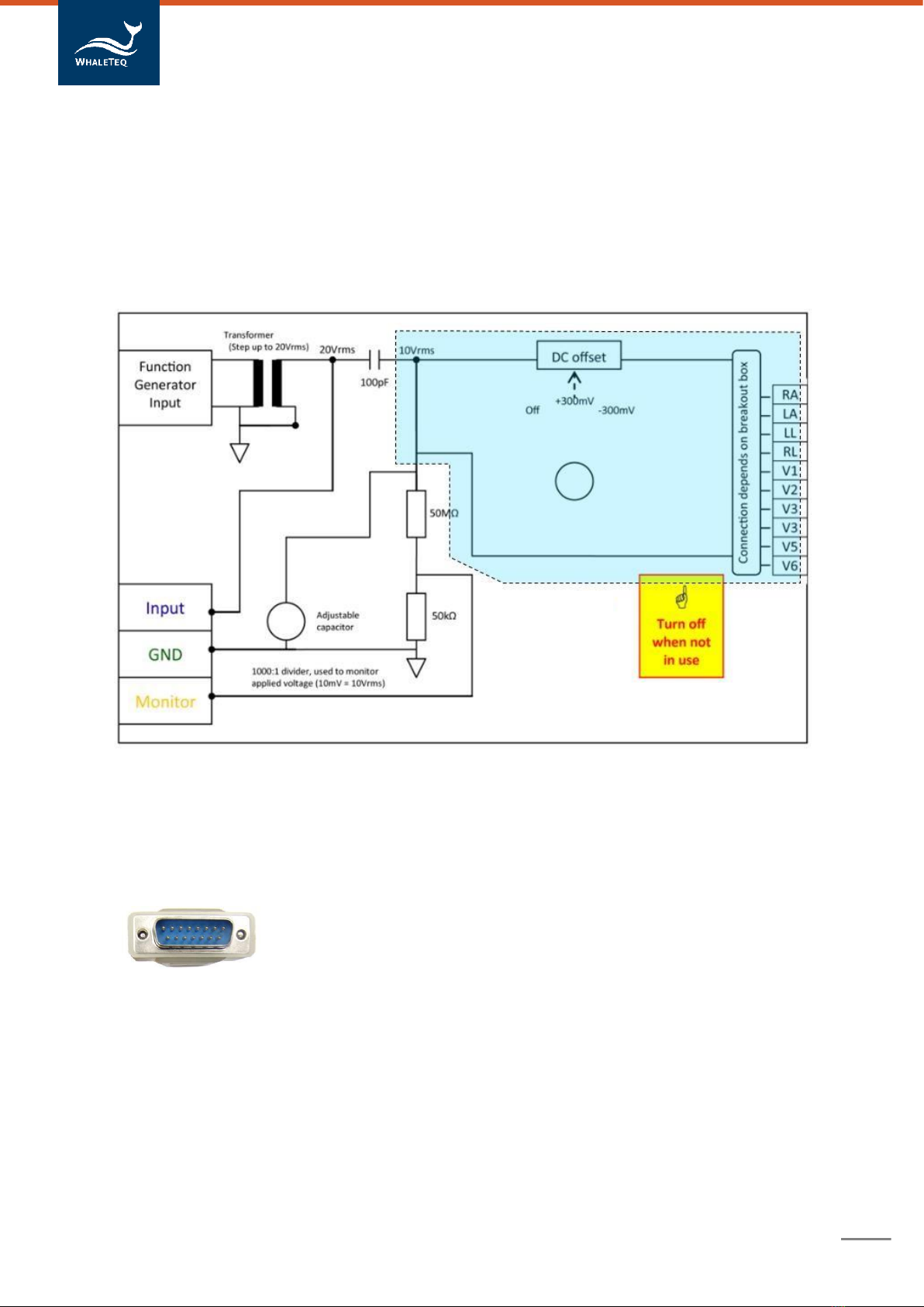
simulates 10Vrms, with an imbalance of 51kΩ//47nF, and allows an indication equivalent to
0.35mVrms (1mVpp). This requires ECG equipment to have a relatively large CMRR of 89dB1.
In practice, ECG equipment handles this large CMRR in five ways:
-Intentional capacitance between the patient circuit and earth, small enough not to cause
leakage current problems, but large enough to load the source, and reduce the voltage
by 50% or more. This is the reason for the 100pF in the testcircuit.
-“Right leg drive”: this is similar to noise reducing headphones, where the “noise” is
sensed on measurement leads (e.g. RA, LA, LL), inverted and then returned via the RL/N
lead electrode. Also referred to a noise cancellation.
-Patient isolation barrier, which reduces the impact of the common modevoltage
-High CMRR input op amps, to handle the residual common modevoltage
-Finally, filtering can be used to remove residual common mode mains noise
While filtering is often used in practice, it is reasonable to confirm that the hardware features can
provide sufficient CMRR without filtering. This ensures that distortion of the signal will not occur.
For this reason, mains notch filtering (ac filter) must be turned off for the test even if it requires
special software to do so. This is one point where the IEC standard differs from US and other
standards.
1This value can be calculated from 20 log10 (10V / 0.35mV)
9

Common Mode Rejection Ratio Tester | User Manual
10
5.3
Test equipment
Refer to the standard for the test circuit.
From a testing point of view the series 100pF introduces significant complications, as it
represents a very high impedance of about 30MΩ at 50/60Hz. This means that attempts to
measure the applied voltage (10Vrms) with a normal multimeter will fail, because the meter has
around 10MΩ input impedance. It is possible to use 1000:1 HV probe with an oscilloscope
(100MΩ/3pF), but noise and other errors can be large. Even 100MΩ/3pF will load the circuit, so
the voltage will change (increase) by about 5% after the HV probe is removed, which should be
accounted for if such probes are used.
WhaleTeq’s equipment incorporates a 50MΩ/50kΩ 1000:1 divider to allow monitoring by a typical
digital multimeter (10mVrms = 10Vrms). The value of 50MΩ has been chosen as the best
compromise between loading the circuit, noise and accuracy. As the divider remains in circuit it
at all times the unloaded applied voltage (without the ECG connected) can be considered
accurate. However, the 50MΩ can slightly change the loaded voltage once the ECG is connected
(because it is resistive, not capacitive). The error introduced will vary based on ECG’s
capacitance to ground, but simulations indicate this error is small and in the very worst case will
still be less than 3%.
The 100pF also creates a problem with the position of the patient cable. If the cable is allowed to
sit on an earthed plane, the stray capacitance can be enough to provide additional loading and
reduce the actual common mode voltage. This stray capacitance is highly variable and thus can
impact the test. For conservative tests, the cable should be supported off the earth plane, but
remain above the earth plane in order to minimize noise.
For IEC 60601-2-25: 2011, IEC 60601-2-27 and IEC 60601-2-51, the test requires a 20Vrms
source. This can be sourced from the mains supply but for those wishing to test at various
frequencies and have good control over the applied voltage, use of a function generator is more
convenient. A function generator is usually limited to 7.1Vrms (20Vpp). To assist with this,
WhaleTeq’s equipment has a small transformer built into the equipment which allows the voltage
to be stepped up to 20Vrms. The applied voltage can then verified at the “Input” and “GND”
terminals.
Common mode rejection is also dependent on impedance imbalance. For this reason, the test
also introduces an imbalance of 51kΩ//47nF in one lead only. Experience from tests indicates
that without this imbalance, there is usually no visible indication on the ECG, but with the
imbalance readings typically range between 3-7mm (0.3 ~ 0.7mVpp). This suggests that the
value of imbalance impedance is critical for the tests. Although the diagram in the standard
shows all switches open, for the purpose of the test, all switches should be closed except the
lead being tested. WhaleTeq’s device takes advantage of this to eliminate all switches.
IEC 60601-2-27 requires a dc offset of ±300mV, while IEC 60601-2-25: 2011 and IEC 60601-2-
51 consider that other tests have proved the ability to handle a dc offset. The dc offset is sourced
by an internal battery. The lifetime of this battery is estimated to be at least 50 hrs, which should
far exceed the lifetime of the equipment if the switch is returned to the “Off” position after use. If
the DC offset switch is accidentally left on continuously (e.g. while in storage), the battery will
require replacement. Contact WhaleTeq for details if this occurs.
Test experience indicates that due to the right leg drive, there can be short period of 1-2s while
the equipment “learns” the noise. This can result in transient response which can be ignored.
Earlier designs of WhaleTeq equipment incorporated the CMRR test circuit inside the USB
module, but found that results were not the same as separate double box construction. The

Common Mode Rejection Ratio Tester | User Manual
11
suspected reason is that the right leg drive is unable to respond correctly if there is other higher
frequency noise around.

Common Mode Rejection Ratio Tester | User Manual
6
Operation
Operation will typically follow these steps:
Step
Procedure
Diagrams
1
Set up noise free environment as described in
Section 3.
2
Connect a function generator to the BNC
terminal.
Alternate: if bypassing the transformer, a test
supply (e.g. 20Vrms, 50 or 60Hz) can be
connected directly to the “Input.” In this case
take care with the Warnings and Cautions
given in Section 7.
Function
Generator
(FG)
Alternate:
Direct mains
(20Vrms)
3
Turn on the source, and adjust to the desired
voltage2 (20Vrms), by monitoring the voltage
between the “Input” to “GND.”
FG: ~3V rms
50 or 60Hz
DMM
(20Vrms)
4
Using a battery operated digital multimeter with
at least 0.1mV resolution, connect to the FG: Off
“Monitor” and “GND” terminals. Keep the leads
and meter on the earthed plane.
Verify that with the source off, the indication on DMM
the meter is <0.5mV. If notcheck adjust <0.5mVrms
grounding, remove nearby noise sources or
choose a different location. If more than 0.5mV
remains, record as a potential source of error3. Earthed plane
Some meters have the ability to filter out higher
frequency noise (above 1kHz), use this feature
if available.
5
If the ECG breakout box is used, make sure
this is connected and also above the earthed
plane.
Note: This is to fix the unloaded capacitance.
The breakout box adds about 10pF load when
sitting on an earthed plane.
Earthed plane
2 Use 20Vrms for IEC60601-2-27, IEC60601-2-51. Refer to the standard for IEC60601-2-47.
3 In general even 1mVrms noise (equivalent to 1V) should not influence a pass/fail result. If the ECG equipment fails the
test (indication >10mm) it may be necessary to reduce noise.
12

Common Mode Rejection Ratio Tester | User Manual
13
Step
Procedure
Diagrams
6
Turn on the supply. Using the “adjustment
capacitor” adjust to 10mVrms (equivalent to
10Vrms) without the ECG device under test
connected. The “adjustment capacitor” can be
adjusted using a small screw driver.
Notes: If metal, insulate the portion of the handle of the
screwdriver which will be touched with 2-3 turns of electrical tape,
and adjust the voltage to around 3-5% lower than the target (e.g.
9.5 ~ 9.7mV). After removing the screwdriver, the voltage typically
increases 3-5%.
The adjustment uses a half plate capacitor without an end stop.
Earlier units used 5-30pF; later units use 6-50pF.
FG: On, ~3V
as in Step 3
DMM
10.0mVrms
Adjustment capacitor
7
Turn the source off, and connect the ECG to
the set up (RA to RA, LA to LA etc), keeping
the ECG leads above the earthed plane.
With the source off, confirm indication on the
ECG is less than 1mm peak to valley (peak to
peak). This is a double check that the
environment noise is sufficiently low.
ECG
under
test
Earthed plane
8
Turn on the source, connect RA to the
imbalance terminal and measure the indication
on all leads (Lead I, II, III, V1 ~ V6).
Note: With RA on the imbalance terminal, an
indication is expected on Leads I, II, but not on
lead III. Also a 1/3 indication on chest leads Vn
is expected due the normal lead relation.
I
II
III
V1
..
V6
9
Repeat the test for all leads by swapping each
lead to imbalance terminal in turn. Repeat the
tests with +300mV and -300mV if required by
the standard.
Note: It is recommended to return each lead to
their original position after each test to avoid
confusion and tangled cables.
RA LA LL RL
10
When complete, ensure the dc is set to off.
This ensures the internal battery is not
depleted.

Common Mode Rejection Ratio Tester | User Manual
14
7
Warnings/Cautions/Notes
Please consider the following warnings / cautions with this equipment:
1. Input other than function generator [WARNING]
If the 20Vrms input is sourced directly (bypass the function generator input/transformer),
take appropriate precautions. In particular:
a. There is no input protection provided
b. Do not apply more than 30Vrms
c. Do not connect a function generator at the same time
d. Use a safety isolation transformer (separation between the 20Vrms circuit and
accessible parts is not designed for safetyinsulation).
2. Residual test set up noise [CAUTION]
It is normal to have a small amount of residual noise (of up to 1mmpp) when no input is
applied. It is not necessary to reduce this further provided the margin between the test
result and the limit is greater than this noise. (e.g. noise = 1mm, limit = 10mm, test result
= 6mm). In other cases, additional efforts should be made to reduce the noise (increase
the metal shield around the test set up, make sure the operator is touching the shield
during the test, or choose a different test location)
If a function generator input is used and the frequency is different to that of the
environment (e.g. input 50Hz, environment 60Hz) the result on the ECG may show some
“beating” with the residual noise from the environment. This beating should be at a
frequency equal to the difference in frequencies (e.g. 10Hz) and not greater in amplitude
than the residual noise when no input is applied.
If the set frequency is nominally the same as the environment (e.g. input 50Hz,
environment 50Hz) the beating may be extremely slow because of slight differences in
frequency (e.g. environment noise 50.00Hz, function generator 50.10Hz would result in
beating with 10s period).
The beating above is not of concern provided the margin to the limit is sufficient.
3. Battery life [CAUTION]
The internal 300mV is sourced from a SR44 1.5V alkaline
battery. By calculation this battery should last in excess of
100hrs, which far exceeds the expected demands during
testing. However, if the user accidentally leaves the DC offset
switch on the battery can be depleted and will require
replacement. This in turn requires disassembly of equipment
including the internal shield. Later models have made this
easier to perform however it is best to avoid this situation by
ensuring that the switch is off in normal use.
4. Warranty void if QC PASS label is removed or tampered with.

Common Mode Rejection Ratio Tester | User Manual
15
8
Specifications
Item
Additional Details
(if required)
Specification
Design
capability
*
Input
transformer
Step up to allow use with a
function generator
Ratio not lower than 4:1 (e.g.
drive voltage 5Vrms or less is
required).
-
Voltage
divider
1000:1 using 50MΩ:50kΩ
Ratio accuracy ±2%
±1%
Series
capacitance
100pF
100pF ± 5%
±5%
Imbalance
impedance, R
51kΩ
51kΩ ±1%
±0.5%
Imbalance
impedance, C
47nF
47nF ± 5%
±5%
DC offset
Internal battery powered
300mV ± 1%
Up to 50hrs with intermittent use
±0.3%
Environment
Intended for normal laboratory
environment. The selection of
critical components is known
to be stable in the range
shown. The 50MΩ divider may
be affected by high humidity in
excess of 85%.
15-30°C
10-75% RH
* Assured by selection of components or adjustment.
9
Contact details
WHALETEQ Co., LTD
service@whaleteq.com | (O)+886 2 2596 0701
9F, No.27, Minquan W. Rd., Taipei City 10452, Taiwan
Table of contents
Other WHALETEQ Test Equipment manuals

WHALETEQ
WHALETEQ CMRR 3.0E User manual

WHALETEQ
WHALETEQ MECG 2.0 User manual

WHALETEQ
WHALETEQ WECG400 User manual

WHALETEQ
WHALETEQ DFS360 User manual

WHALETEQ
WHALETEQ DFS360 User manual

WHALETEQ
WHALETEQ SEEG 100E User manual

WHALETEQ
WHALETEQ HRS200 User manual

WHALETEQ
WHALETEQ HFPA150 User manual

WHALETEQ
WHALETEQ AECG100 User manual

WHALETEQ
WHALETEQ CMRR 3.0 User manual
Popular Test Equipment manuals by other brands

JDS Uniphase
JDS Uniphase SmartClass user guide

Carrier
Carrier COBRA 48/50HJ004-014 Installation and service

Agilent Technologies
Agilent Technologies 16048G Operation and service manual

Horiba Scientific
Horiba Scientific 6560S-10C instruction manual

Megger
Megger PAT4DV/3 user guide

PROVA
PROVA CM-03 user manual