WHALETEQ SEEG 100E User manual

Single Channel EEG Test System | User Manual
1
WHALETEQ
Single Channel EEG Test System
(SEEG 100E)
User Manual
Revision 2020-10-21
PC Software Version 1.0.5.10

Single Channel EEG Test System | User Manual
2
Contents
1 Introduction ..........................................................................3
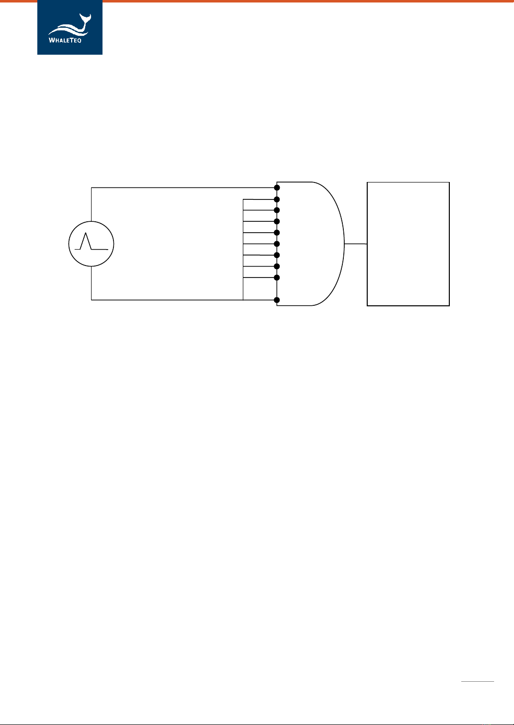
1.1 Basic concept ............................................................................................. 3
1.2 Standards/Application ............................................................................... 4
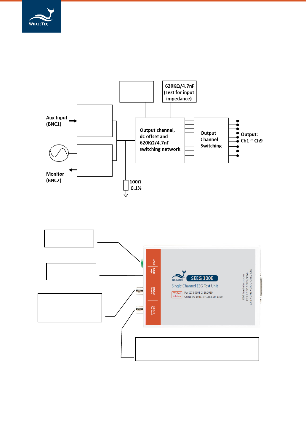
1.3 Block diagram/SEEG 100E Module overview............................................. 5
1.4 Main specifications .................................................................................... 6
1.5 Cautions ..................................................................................................... 6
2 PC Software Mode ................................................................7
2.1 Installation and Environment..................................................................... 7
2.1.1 System requirements........................................................................................ 7
2.1.2 SEEG Software Installation................................................................................ 7
2.1.3 First Time Using WhaleTeq Product - USB Driver Installation .......................... 8
2.1.4 First Time Using WhaleTeq Product –Microsoft .Net Framework 4.0
Installation................................................................................................................... 9
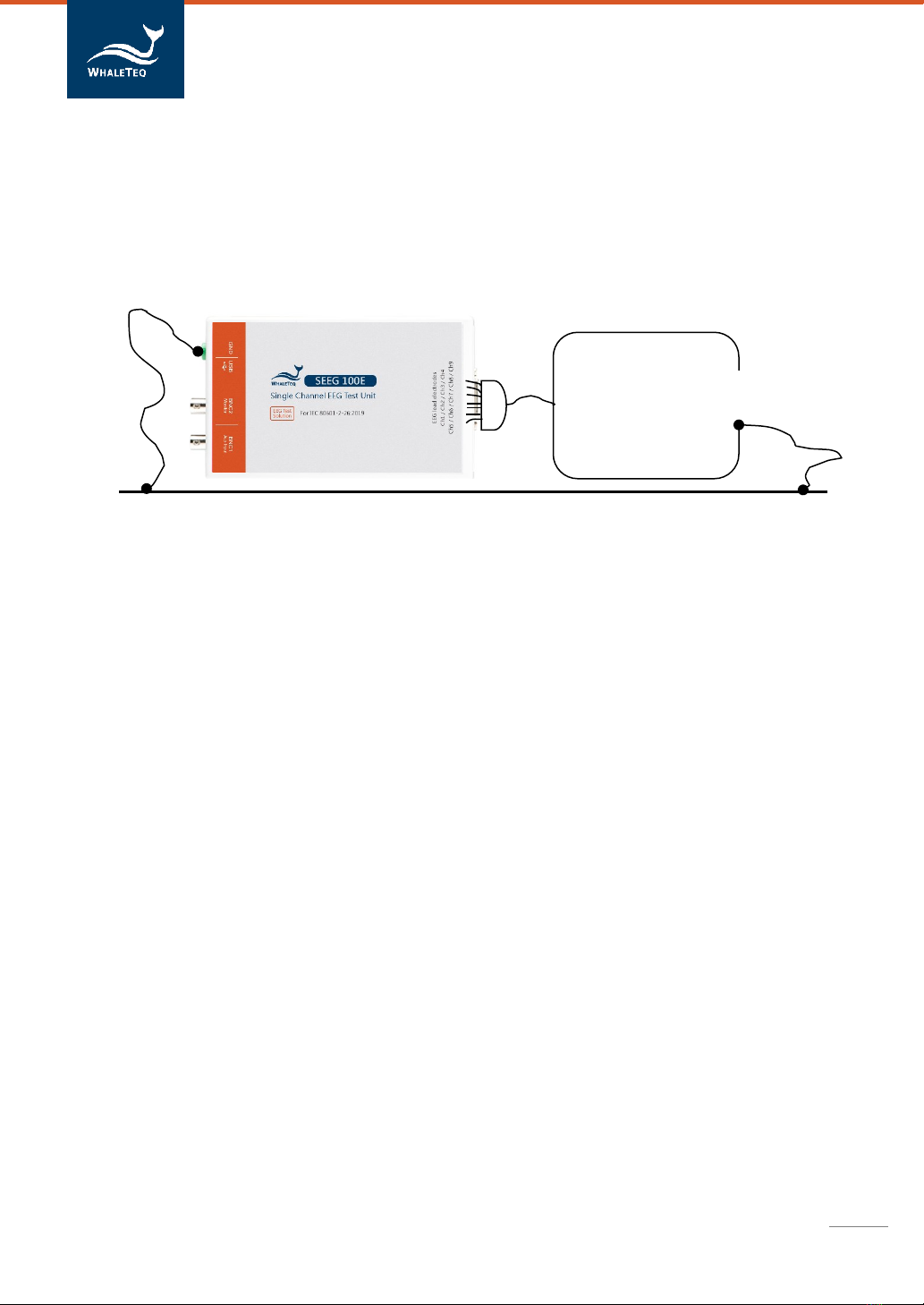
2.2 Connecting to the EEG ............................................................................... 9
2.3 Environment, noise reduction ................................................................. 10
2.4 Main screen.............................................................................................. 11
2.5 Description of Functional groups............................................................. 12
2.5.1 Main function (main waveform)..................................................................... 12
2.5.2 Main parameters ............................................................................................ 13
2.5.3 DC offset setting ............................................................................................. 13
2.5.4 Input impedance test...................................................................................... 14
2.5.5 Output lead electrode..................................................................................... 14
2.5.6 Output graphic display.................................................................................... 14
2.5.7 Special functions............................................................................................. 15
2.5.8 Special waveforms and load waveform .......................................................... 15
2.6 IEC 80601-2-26 Helper............................................................................. 16
2.7 Calibration, software validation............................................................... 17
2.7.1 Calibration procedure..................................................................................... 18
3 Trouble shooting.................................................................20
4 Contact details ....................................................................20

Single Channel EEG Test System | User Manual
3
1 Introduction
1.1 Basic concept
WhaleTeq Single Channel EEG Test System provides a single waveform to one or
more lead electrodes of EEGs, for testing to IEC particular standards. The following
diagram shows the single channel concept:
(Figure 1) Single channel concept
Via a SEEG 100E, the system produces arbitrary waveforms (streamed from the PC
with digital to analogue conversion) at up to ±1V, which is then applied to a
precision 500:1 divider to produce the voltages at up to ±1mV level (2mVpp). The
SEEG 100E contains resistor/capacitor networks, dc offset, and relay switching to
provide the full range of single channel performance tests in IEC standard.
The basic range of tests in the standards include, for example:
- Sensitivity (accuracy of the μV/mm indication)
- Frequency response (sine wave, and impulse tests)
- Input impedance
- Noise
For a full list of tests, refer to the standard together with Section 1.2.
The limitations of the system are as below:
-Exclude input noise and CMRR tests (this requires a special noise free test
unit, available from WhaleTeq)
-There are 22 terminals (Ch1~Ch22) in EEG breakout box. However, there are
only 9 terminals (Ch1~Ch9) could output waveforms, and the rest 13
terminals (Ch10~Ch22) are connected to ground. Please refer to section 2.2
for details.
Ch1
Ch2
Ch3
Ch4
Ch5
Ch6
Ch7
Ch8
Ch9
Ch10~Ch22
EEG device
under test
(DUT)

Single Channel EEG Test System | User Manual
4
1.2 Standards/Application
The following table shows the standards for which this system has been designed
for, and includes any limitations:
Standard
Clause(s)
Limitations/Notes
IEC 80601-2-
26:2012
201.12.1
201.12.1 all performance tests except
201.12.1.104 input noise and
201.12.1.106 CMRR tests
General limitation:
(1) This equipment is designed for use with isolated EEG circuits, as are generally
provided for medical EEG. If applied to a non-isolated circuit, the noise may be
excessive.
(2) In EEG breakout box, there are 22 terminals. But there are only 9 terminals
could output waveforms, the rest 13 terminals are connected to ground.

Single Channel EEG Test System | User Manual
5
1.3 Block diagram/SEEG 100E Module overview
The following is a simplified block diagram of the system inside the SEEG 100E
module:
Additional input to allow connection to an
external function generator. Precision divider
ensures that 1V in = 2mV out (±0.2%)
Connects to the
PC via USB 2.0
GND, for noise
reduction
Allows monitoring of
the applied signal pre-
divider
(1V = 2mV output)
500:1
Divider
(50KΩ
0.1%)
500:1
Divider
(50KΩ
0.1%)
Precision dc
offset
±150mV

Single Channel EEG Test System | User Manual
6
1.4 Main specifications
In general, the system has been designed in accordance with IEC 80601-2-26:2019
standard. Test parameters and specifications required for testing are listed as
following:
Parameter
Specification
Main output voltage accuracy
±1% for amplitudes of 50 µVpp or higher
Main output voltage resolution
(DAC resolution)
0.5µV
Frequency / pulse repetition
rate accuracy
±1%
Pulse duration / timing accuracy
±1ms
Resistor tolerance
±1%
Capacitor tolerance
±5%
Precision 500:1 divider
(50KΩ:100Ω )
±0.2%
Sample rate
5kHz ± 0.1%
DC offset (fixed, noise free,
from internal super capacitor)
150mV ± 1%
DC offset (variable, may include
up to 50µVpp noise)
Setting ±1% or ±3mV
Power supply
USB +5Vdc supply (no separate power supply
required) 0.5A (high power mode)
Environment
15 ~ 30°C (by design, not tested)
30 ~ 80% RH(design not tested)
Safety, EMC standards
No applicable safety standards (maximum
internal voltages 12Vdc) For EMC no testing
performed. CE marking based on careful
selection of parts, including USB protection IC,
as well as special filters to reduce noise from
microprocessor (8MHz) and DC/DC converter
(200kHz).
1.5 Cautions
➢Before using products, use a grounded wrist strap or touch a grounded
object or a metal object, such as the power supply case, to avoid damaging
them due to static electricity.
➢WhaleTeq does not recommend to connect test equipment with DUT to
conduct Electrostatic Discharge (ESD) test. This may cause unexpected

Single Channel EEG Test System | User Manual
7
damages to test equipment. Please contact WhaleTeq for alternatives
before ESD test.
➢Warranty void if QC PASS label is removed or tampered with.
2 PC Software Mode
2.1 Installation and Environment
2.1.1 System requirements
The Single Channel EEG system uses a normal PC to interface and control the
USB module.
PC requirements:
-Windows PC (Windows 7 or later, suggest to use the genuine version)
-Microsoft .NET 4.0 or higher
-Administrator access (essential for installing software, driver, and
Microsoft .Net Framework)
-1.5 GHz CPU or higher
-1GB RAM or higher
1
-USB port
2.1.2 SEEG Software Installation
Please follow the below steps to download and execute SEEG Software.
․Download SEEG software from WhaleTeq website.
․Browse to the download location
․Unzip the file to your destination folder
․Click the installation file in the destination folder to initiate the installation
process.
․When the installation is completed, SEEG software would be executed
automatically. User can also execute SEEG software via selecting “All
Programs” →“WhaleTeq” →“WhaleTeq SEEG” in Windows startup
program manager.
1
Relative to normal PC processing, there is no special use of PC speed. However, there has been
noted a slow increase in system RAM usage over long periods of time up to 30-40MB (related to MS
Windows “garbage collection”). PCs with only 512MB or less installed and are running several other
programs (in particular, Internet Explorer), may exceed the available RAM, requiring access to the
hard drive and dramatically impacting speed. In this case, streaming interruptions and other
problems may occur.

Single Channel EEG Test System | User Manual
8
If SEEG software can’t be executed properly or this is the first time using
WhaleTeq product, please refer to section 2.1.3 and 2.1.4 to confirm that
USB driver and Microsoft .Net Framework 4.0 are all installed.
2.1.3 First Time Using WhaleTeq Product - USB Driver Installation
If Windows device manager can’t recognize WhaleTeq product, please follow
the below instructions to Install Microchip® USB driver.
Microsoft Windows 10
As Windows 10 has built-in Microchip® USB Driver, there’re no needs to install
any drivers. It just takes a while for Windows Device manager to recognize and
install the driver.
Microsoft Windows 8 and Windows 8.1
․Windows 8 and Windows 8.1 can’t recognize SEEG unit, please download
“mchpcdc.inf” from WhaleTeq website. This driver is provided by
Microchip® for using with PIC microprocessors having built-in USB
function.
․As mchpcdc.inf provided by Microchip® does not contain digital signature,
please disable driver signature enforcement in Windows 8 and Windows
8.1. Please click here to watch the tutorial video.
․When the USB module is connected for the first time, select manual
installation, and point to the folder containing the above file. Then
continue to follow the instructions to finish the installation. There may be
a warning that the driver is not recognized by Windows®, and this can be
ignored. Please click here to watch the tutorial video.
Microsoft Windows 7
․Windows 7 can’t recognize SEEG unit, please download “mchpcdc.inf”
from WhaleTeq website. This driver is provided by Microchip® for using
with PIC microprocessors having built-in USB function.

Single Channel EEG Test System | User Manual
9
․When the USB module is connected for the first time, select manual
installation, and point to the folder containing the above file. Then
continue to follow the instructions to finish the installation. There may be
a warning that the driver is not recognized by Windows®, and this can be
ignored. Please click here to watch the tutorial video.
2.1.4 First Time Using WhaleTeq Product –Microsoft .Net Framework
4.0 Installation
WhaleTeq software is developed by Microsoft .Net Framework 4.0. If SEEG
software fails to launch properly, please check whether Microsoft .Net
Framework 4.0 or higher versions was installed in the operation system.
If your PC does not install Microsoft .Net Framework 4.0 or higher versions,
please download from Microsoft website. Please click here to watch the
tutorial video (from 2:03).
2.2 Connecting to the EEG
For connecting the EEG device to the SEEG 100E and use the provided 22 channels “EEG
breakout box”. There are only 9 terminals (Ch1~Ch9) could output waveforms, and the rest
13 terminals (Ch10~Ch22) are connected to ground. Below is the photo of EEG breakout
box.
Alternately the EEG device under test can be directly connected to the SEEG 100E module
using a male D15 connector. The pin outs are:
1-Ch1 4 –GND 7 –Ch610 –Ch9
2-Ch2 5 –Ch48 –Ch7
3-Ch3 6 –Ch59 –Ch8
Note: Ch10 ~ Ch22 connect to pin 4 (GND).

Single Channel EEG Test System | User Manual
10
2.3 Environment, noise reduction
A noise free environment is necessary for testing EEG equipment. This can be achieved
relatively easily by (a) using a metal bench or metal sheet underneath the EEG device
under test and the WhaleTeq SEEG test unit, and (b) connecting SEEG GND terminal to the
sheet and also the frame ground (or EP terminal) of the EEG device under test:
With this set up, turn the EEG device under test to maximum sensitivity, turn off the ac
filters (if possible) and confirm that the level of noise is acceptable for tests. For most tests,
this set up is satisfactory without any special efforts. However, for the input impedance
test with the 620kΩ is in series the imbalance in impedance can cause high noise. For this
test, the ac filter may be turned on. If the noise is still excessive, move to an electrically
quiet environment or increase the size of the metal sheet underneath and around the set
up.
EEG Device
Under test
Frame ground
or EP terminal
Metal bench, metal sheet or foil

Single Channel EEG Test System | User Manual
11
2.4 Main screen
01-Select the main function (waveform) type, such as sine, triangle and square wave.
02-Select the pulse function (waveform) type, such as rectangle pulse, triangle pulse and
Hysteresis.
03- Parameter setting
04- Select the pulse width for rectangle and triangle pulse only, time constant for
hysteresis only.
05- DC offset setting.
06- Select if 620kΩ/4.7nF is in circuit (for input impedance test).
07- Select the lead electrode which the output is switched to (Ch1~Ch9).
08- Special functions
09-Select PhysioNet EDF format waveform and download directly from Internet
10- Load text and binary format waveforms from local.
11-Provide a semi-real time graphical display of the current signal
12-Reset to default
13-Calibration mode
14-IEC-80601-2-26 helper

Single Channel EEG Test System | User Manual
12
2.5 Description of Functional groups
2.5.1 Main function (main waveform)
This group allows the operator to select the main waveform to be used in the test, from
the following:
Waveform
type
Description
Sample waveform
Sine
Basic sine wave, according to
the amplitude (mVpp) and
frequency (Hz).
Triangle
Basic triangle wave, according
to the amplitude (in mVpp)
and frequency (Hz).
Square
Basic square wave, according
to the amplitude (in mVpp)
and frequency (Hz).
Rectangle
pulse
A rectangular pulse, according
to the amplitude setting,
pulse width and pulse
repetition rate (frequency,
Hz).
Triangle
pulse
A triangle pulse, according to
the amplitude setting, base
(pulse) width and pulse
repetition rate (frequency,
Hz).
Hysteresis
Exponential waveform, used
for hysteresis test (set
amplitude to ±0.5mV, time
constant 50ms, adjustable).
EDF File
Manager,
Load
Waveforms
A range of stored waveforms
including: (1) load waveform
and (2) load PhysioNet
database through internet,
then play.
For these waveforms, the
amplitude and frequency
settings have no effect.

Single Channel EEG Test System | User Manual
13
2.5.2 Main parameters
Amplitude:
Can be set in either mV or µV, changing one will
automatically change the other to match. The waveform
amplitude from -2 mV to +2 mV at a 0.001mV (1 µV)
resolution. For all waveforms the amplitude represents the
peak to peak value. For example, for a 1mV sine wave the
actual waveform varies between +0.5mV and -0.5mV. This
correlates with testing requirements in standards.
Frequency:
Set in either Hz. Continuous waveform (Sine, Triangle and
Square), can up to 500 Hz, for pulse waveforms (rectangle,
triangle), the frequency can also be referred to as the pulse
repetition rate. For some pulse settings the frequency is
limited to prevent overlapping pulses (limit to 5 Hz).
Pulse Width:
Apply to rectangle, triangle and exponential pulse
waveforms only. For the rectangle, pulse width is defined as
the time between crossing the 50% point in rising and falling
edges of the pulse
2
. For triangle pulses, the setting matches
the base of the triangle pulse. For exponential pulse, the set
pulse width is time constant. Pulse width can be set to down
to 2ms
3
.
2.5.3 DC offset setting
This function allows the operator to switch in a dc offset. In the
default condition (not variable), only +150mV, 0 or -150mV can
be set. In this mode, the dc offset is sourced from an internal
“super capacitor” which at least 3 minutes of accurate and
stable 150mVdc offset to be placed in series with the main
waveform, without impacting the quality of that main
waveform. The capacitor is charged while not in use (i.e. when
the setting is zero).
In the variable mode, the dc offset is provided by a second
channel. It is limited to 1000mV.
2
To minimise ringing due to EEG notch filters, rectangle pulses have a rise time of 1ms. This means
that a 20ms rectangle pulse will actually have a 21ms base and a 19ms at the top of the pulse. This
definition ensures that the pulse integral matches the setting, e.g. a 3mV 100ms pulse will have an
integral of 300µVs.
3
Note the sampling rate is limited to 0.2ms. Therefore, a 2ms pulse will have limited time resolution.

Single Channel EEG Test System | User Manual
14
2.5.4 Input impedance test
This check box allows the user to switch in an impedance of
620kΩ//4.7nF in series with the main function, for testing the
input impedance of the EEG device under test. When the
check box is ticked, the impedance is shorted. The ±150mVdc
offset can be used in conjunction with this test.
2.5.5 Output lead electrode
This section allows the user to select which lead electrode the
output is connected to (i.e. terminal P1 in the IEC 80601-2-26:2019,
Figure 201.104). Unselected electrodes are connected to the
system ground (terminal P2 in Figure 201.104).
More than one lead electrode may be selected.
2.5.6 Output graphic display
The output display provides an image similar to that provided by EEGs. The
sensitivity of the display range may be set at 0.1mm/µV, 0.05mm/µV or
0.02mm/µV to cover the full range of waveforms offered by the system. The
time rate is fixed. The output display uses the same data as used in the DAC
output and serves as a cross check of the selected waveform.

Single Channel EEG Test System | User Manual
15
2.5.7 Special functions
Baseline reset test (sine wave only):
When checked the parameters are ignored and a large
signal of 1Vpp (0.354Vrms) is applied. It is intended to
test the EEG’s response to overload, in particular
automated resetting of baseline (due to high pass
filtering). When unchecked, the system reverts to the
previous settings (e.g. 1mVpp 10Hz signal). Mains
frequency of the test can be selected from 50Hz or
60Hz.
Frequency scans:
Sine: may be used to test systems with extended
frequency response. This system uses a fixed sampling
rate of 5kHzwhich has been found to reduce problems
of beating from other digital sources. If beating still
occurs, a separate analogue input at BNC1 is provided
to allow testing with analogue type function
generators.
2.5.8 Special waveforms and load waveform
There are two features on the bottom right frame: “Special Waveforms” and
“Load waveform”. For these two features, the amplitude and frequency
settings have no effect.
Special Waveforms:
WhaleTeq SEEG can play PhysioNet waveforms with 1 electrode at each time.
This feature will download waveforms from PhysioNet directly. Please check
your internet status before use this feature.
The SEEG built-in databases are as below:
-EEG Motor Movement/Imagery Database (eegmmidb)
:
Each volunteer performed different motor/imagery tasks while 64-
channel EEG were recorded. Here for more details.
-CHB-MIT Scalp EEG Database (chbmit)
:
This database, collected at the Children’s Hospital Boston, consists of
EEG recordings from pediatric subjects with intractable seizures. Each
seizure is annotated. Here for more details.

Single Channel EEG Test System | User Manual
16
Load waveform:
The “Load waveform” function supports three formats –Text, Binary and EDF
files.
Text (*.txt)
- Ascii file, Windows line breaks (LF, CF)
- first line is sample rate (Hz)
- second line number of samples
- following lines are samples in microvolts (one sample per line)
Binary files (*.bin)
- Bytes 1-2 are sample rate (Hz)
- Bytes 3-6 are number of samples
- Following bytes are samples, 2 bytes per sample
- all data is big-endian (high byte first), 2's compliment
EDF files (*.edf)
This is a commonly used but complicated format. Here for the format
details.
2.6 IEC 80601-2-26 Helper
It is a companion software add-on to enhance the function of SEEG 100E. It supports the
latest EEG standards IEC80601-2-26:2019 with detailed preset parameter settings and
actual test sequence for testing needs.

Single Channel EEG Test System | User Manual
17
2.7 Calibration, software validation
WHALETEQ SEEG 100E has undergone a detailed system validation including software. A
report for this can be provided on request.
Prior to shipping, each unit is tested for component values and output voltages, using a
calibrated precision multi-meter. As WhaleTeq cannot provide ISO 17025 accredited
calibration, laboratories which are required to follow ISO 17025 should perform calibration
either periodically or on a before use basis, following normal procedures and practice. The
extent of calibration may be limited depending on the needs of the laboratory.
As the calibration procedure is complicated, a software assisted calibration mode is
provided. The software sets up the SEEG as required for the particular tests, and instructs
the user on what measurement to make (e.g. measure resistance between ch1 and ch2).
The user then enters the results into the form provided, and the software checks if the
results are within allowable limits. When complete, the results of calibration are
automatically copied to the notepad and stored in a text file at:
C:\WhaleTeq\SEEG_Cal_yyyymmdd.txt
Where “yyyymmdd” is the date based on the PC’s system. If a fixed width font such as
“Courier New” is used, the data appears aligned.
The following manual procedure is retained here for reference and explanation.

Single Channel EEG Test System | User Manual
18
2.7.1 Calibration procedure
Parameter
Nominal
value,
tolerance
Method
Input
impedance
resistor
620kΩ±1%
This can be measured as follows:
•Set Main function to “Off”
•Set output to ch1
•Uncheck “620KΩ/4.7nF”
Measure the resistance between ch1 and ch2
Input
impedance
capacitance
4.7nF±5%
Measure as for the 620kΩ above, using a
capacitance meter at 1kHz. Note: there is
about 100pF stray capacitance in the circuit
which is included in the measurement.
However, even with this the measured result
is within the limit.
Precision
divider ratio
(50kΩ:100Ω)
500:1 ±0.1%
Resistance values are specified as 50kΩ and
100Ω ± 0.1%, but these cannot be verified
once in circuit. An alternate method is used to
verify the accurate ratio:
•Set up a 2mVpp 0.1Hz square wave to
output ch1
•Using the Fluke 8845A or equivalent
precision meter, measure and record
the peak to peak voltage at BNC2 by
zeroing during the negative cycle, and
measuring at the positive cycle
(nominally 1Vpp).
•Repeat this measurement at the
output between ch1 and ch2
(nominally 2mV)
Calculate the ratio and confirm it is 500:1
±0.2%
Output
voltage
Setting ±1%
Method:
•Set up 0.2mVpp 0.1Hz square wave,
output to ch1
•Measure the peak to peak output
between ch1 and ch2, using the Fluke
8845A or equivalent, record this as
output mVpp
•Repeat for 0.4, 0.5, 0.8, 1, 1.5 and
2mVpp

Single Channel EEG Test System | User Manual
19
•Confirm all values are within 1% or
5µV of the set value
•Note: The Fluke 8845A has suitable
accuracy at 10mVpp but has
borderline accuracy at 1mVpp and
lower. An alternate method is to
measure the output at BNC2 and then
use the divider ratio above.
DC offset
(fixed
±150mV)
150mV ±1%
Method:
⚫Set the equipment to “Off”
⚫Select +150mV
⚫Measure the voltage between Ch1
and Ch2
Note: the DC offset is sourced from an
internal super capacitor which will discharge
after ~10min. Tests in the standard are
typically less than 2 minutes.
DC variable
Setting ±5mV
or 1%
Use the following procedure:
⚫Set the equipment to “Off”
⚫Select the “Variable” checkbox
⚫Set to +200mV dc offset
⚫Confirm the value is 200±5mV
⚫Repeat for +600, +1000, -200, -600
and -1000mV
Output
frequency
Setting ±1%
Method:
•Set up 1mVpp 10/40Hz sine wave
•Measure the frequency at BNC2 using
any appropriate meter
⚫Note: this verifies whether the system
clock is accurate. Verification of other
frequencies or timing is not as this is
covered by software validation,
although users are free to measure
other frequencies and timing. The use
of 40Hz is recommended to avoid
beating with mains frequency.

Single Channel EEG Test System | User Manual
20
3 Trouble shooting
Problem
Resolution
SEEG 100E module
(test unit) not
recognized (USB driver
is installed correctly)
Recognition of USB devices needs to be done in
order:
1) Close WhaleTeq software if open
2) Disconnect the USB module for ~2s
3) Reconnect the USB module
4) Wait for the recognition sound
5) Start WhaleTeq software
SEEG 100E module
stops responding
Move the main function mode to “Off” and then
return to the function being used. If this does not
work, close WhaleTeq software, disconnect the SEEG
100E module, reconnect the SEEG 100E module and
re-start the SEEG 100E module.
4 Contact details
WHALETEQ Co., LTD
service@whaleteq.com | (O)+886 2 2596 0701
9F, No.27, Minquan W. Rd., Taipei City 10452, Taiwan
Table of contents
Other WHALETEQ Test Equipment manuals

WHALETEQ
WHALETEQ HRS200 User manual

WHALETEQ
WHALETEQ WAIOT-N User manual

WHALETEQ
WHALETEQ AECG100 User manual

WHALETEQ
WHALETEQ DFS360 User manual

WHALETEQ
WHALETEQ CMRR 3.0 User manual

WHALETEQ
WHALETEQ DFS360 User manual

WHALETEQ
WHALETEQ SECG 4.0 User manual

WHALETEQ
WHALETEQ CMRR 2.0 User manual

WHALETEQ
WHALETEQ MECG 2.0 User manual

WHALETEQ
WHALETEQ HFPA150 User manual
Popular Test Equipment manuals by other brands

Tektronix
Tektronix ST112 user manual

Launch
Launch X-431 ADAS PRO user manual

B+K precision
B+K precision 2522B instruction manual

Kyoritsu Electrical Instruments Works, Ltd.
Kyoritsu Electrical Instruments Works, Ltd. 8031 CE instruction manual

Agilent Technologies
Agilent Technologies 2000 X manual

Additel
Additel ADT672 user manual