manuals.online logo
Brands
  1. Home
  2. •
  3. Brands
  4. •
  5. Wheatstone
  6. •
  7. Recording Equipment
  8. •
  9. Wheatstone ARCUS User manual

Wheatstone ARCUS User manual

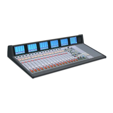
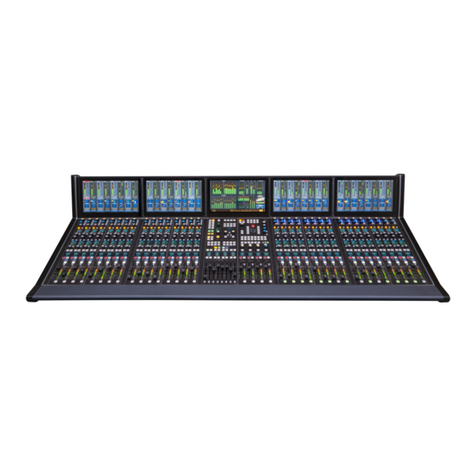
SURFACE COMPONENTS (ARCUS-32 SHOWN)
1 of 3 011598 rev A
ARCUS TELEVISION CONSOLE
MULTI-TOUCH MONITORS*
CHANNEL MONITORS (FADERS 1 - 16) MAIN MONITOR CHANNEL MONITORS (FADERS 17 - 32)
FOUR FADER MODULES * CONTROL & MASTER MODULES FOUR FADER MODULES*
(CHANNELS 1 - 16) (SUBMIX, VCA GROUPS, MASTERS, MONITORS) (CHANNELS 17 - 32)
Quick Sta Guide
FADER CHANNEL STRIP CONTROLS FADER CHANNEL MONITOR DISPLAYS
* The number of monitors and fader modules is set by the frame size
1
4
7
14
15
22
34
2
3
5
6
89
12 13
16 17
20 21
23 24
26 27
28
29
30
31
32
33
35
10
11
18
19
25
1. INPUT TRIM CONTROL - Adjusts the channel source’s input gain.
2. ISOLATE - Isolates the channel from global preset changes when lit.
3. AUTOMIX - Identies that channel is part of an AutoMix group when lit.
4. INPUT SELECT ENCODER - Use to select and take a new channel source.
5 - 6. PRESET SOURCES - Tap the A or B button to recall a preset source. Press/hold the
A or B button to change the source assigned to that A or B button.
7 - 22. WILD CONTROLS & DISPLAYS - The four encoders, eight buttons, and two displays
are used to view and adjust various channel parameters. The encoders (7, 14, 15, 22) are
used to both select and to then adjust a parameter along with the buttons (8, 9, 12, 13, 16,
17, 20, 21) and displays (10, 11, 18, 19). The channel control functions are saved/recalled as
a group using the Control Module’s Wild Preset buttons, or universally changed by using
the Control Module’s Function Expand buttons.
23 - TB (TALKBACK)
Used by the board operator to talk to that channel’s bus-minus output.
24 - VCA
Adds the channel to a VCA group when lit.
25 - CHANNEL OLED DISPLAY
Shows the current source name and signal mode in the top half of the display. The source
info when Page is active for this channel is shown in the bottom half of the display.
26 - MUTE
When lit, the channel is muted. When unlit, the channel is feeding all assigned busses.
27 - SEL (Select)
When lit, indicates this channel is the selected channel which changes the channel
monitor to show channel-specic settings for quick updates to the channel settings.
28 - SPILL
Sends the channel’s audio to adjacent faders so those channel faders can be adjusted to
balance the audio. Most oen used with 5.1 sources.
29 - PAGE
Toggles the channel between showing Page A settings (unlit) and Page B settings (lit) for
the active Layer.
30 - AFL (AFTER FADER LISTEN)
Sends the channel audio, post fader, to the CR monitor.
31 - AUTOMIX INDICATORS
LEDs indicate whether the channel is in an Automix Group as a Master or Slave signal.
32 - INPUT LEVEL METER
Shows the source input levels of the source currently feeding that channel.
33 - GAIN REDUCTION METER
Shows the amount of Gain Reduction being applied to the channel audio.
34 - FADER
Controls the audio going to the assigned busses. For unity gain, align the fader knob line
with the thick line at -12.
35 - PFL (PRE-FADER LISTEN)
Sends the channel audio, pre-fader and pre-switch, to the PFL meter & cue output.
NORMAL CHANNEL DISPLAYS
When no channel SEL buttons are lit, eight channel settings
are shown in the display. The channel number and On-Air
indicator is at the top. Input level and gain reduction meters
along with mode, delay, input gain, and master bus assign-
ments are in the middle. Mini EQ & Dynamics graphics show
their current settings with two Page presets below. Pressing
Aux Sends brings up a mini Aux Send control screen.
CHANNEL SEL ACTIVE DISPLAY
When a channel SEL button is lit, the channel monitor display
behind that channel changes to show the Input View (shown
above) so the board operator can quickly adjust various
channel parameters. The buttons along the bottom of the
display bring up additional displays to adjust Bus Assigns, EQ,
Dynamics, 5.1 signal panning, set AutoMix weightings, and a
adjust the Aux Sends. Tapping the Exit button returns the
monitor to its normal display, turning o the SEL button on the
active fader channel.
2 of 3
CONTROL MODULE MASTER MODULE
1 - WILD METER & LOUDNESS RESET
The four Meter buttons are set to sources that
need to be quickly shown on the WILD METER.
The Loudness Reset button resets the Program
Duration timer. Press/hold to reset it to 00:00.
When lit, the timer is running, when unlit, the
timer is paused (press again to resume).
2 - LAYER CONTROLS
Up to ten Layers can be created to setup the
channels for various shows or applications.
The Side Shift and Page keys allow one to
sequence thru the Layers or to toggle between
Pages A & B on each layer.
3 - PAN & DELAY
Panning and delay controls/display on a
selected channel (channel SEL button is lit).
4 - COPY & PASTE
Used to copy all or selected settings on one
channel to paste into another channel.
5 - X-Y ROUTER
Connects a Source to a Destination using the
two encoders and Take buttons.
6 - WILD PRESETS
Allows the four most commonly-used channel
Wild Control settings to be saved then recalled.
7 - FUNCTION EXPANSION/INFO DISPLAYS
These affect the programmable channel controls
and their OLED displays and channel monitors.
8 - WILD FADER CONTROLS
The eight faders control various functions by
which Fader Mode and bank select button is lit.
The OLED displays show the active function. The
SEL buttons allow various parameters to be set
for the active wild fader sources. PFL allows a
source to be separately monitored pre-fader.
1 - REH, AIR & SPARE BUTTONS
REH (Rehearse) and AIR (on-air)
toggle console operations between
off-air and on-air functions. The
four Spare buttons are all user-set.
The Increment encoder is used to
step thru lists and select items.
2 - CLIP PLAYER CONTROL
With a USB thumb drive with audio
files in the Clip port, the Hot Clip
Select buttons are a quick way to play
up to eight preassigned audio tracks.
3 - TALKBACK CONTROLS
TB 1 - 8 have user-set destinations,
which are listed in the OLED display.
AFL/PFL Clear cancels all AFL and PFL.
4 - LEVEL CONTROLS
Sets the level of Dim, Talkback, AFL,
and PFL going to the monitor outputs.
5 - PROGRAMMABLE BUTTONS
These buttons are user-set and have
no pre-defined functions.
6 - MONITOR CONTROLS
The console supports three Studios
and a Control Room (CR) with speaker
level controls, talkback (TB), Select
(SEL), Dim, six monitor sources, and
three CR speaker selector buttons.
7 - MASTER OUTPUT CONTROLS
Four dedicated control strips for the
Master Outputs (two 5.1 Surround and
two Stereo). Each control strip has a
master fader plus PFL, AFL, and
Select (SEL) buttons along with Output
Level and Gain Reduction meters.
1
1
2
2
3
3
4
4
5
5
6
6
7
7
8
MAIN MONITOR - HOME VIEW
MAIN BUS METERING
SUBMIX & MIX-MINUS METERING
5.1 SURROUND 1 / STEREO 1 / SWITCHED / STEREO 2 / 5.1 SURROUND 2
LOUDNESS
MONITOR
ARCUS
STATUS
DISPLAY
AUX MASTERS
& TRACK
METERING
ARCUS TELEVISION CONSOLE Quick Sta Guide
THE VIEW BUTTONS OVERLAY DIFFERENT VIEWS ONTO THE MAIN MONITOR FOR QUICK OPERATOR ADJUSTMENTS
ARCUS TELEVISION CONSOLE Quick Sta Guide
3 of 3
SOME OF THE VIEWS WHICH CAN BE OVERLAID ONTO THE MAIN MONITOR
REVERSE ROUTE VIEW
MIX MINUS MASTERS VIEW
EVENT VIEW
STATS & ALARMS VIEW
BUS ASSIGN VIEW
CLIP PLAYER VIEW
ARCUS SURFACE, REAR PANEL CONNECTIONS
GIBRALTAR IP MIX ENGINE, REAR PANEL CONNECTIONS
Shown with optional Redundant Power Supply & optional Redundant CPU
DARS (Digital Audio Reference Signal)
Unused in this application
Gigabit Ethernet
(connect to WNIP System switch port)
100 MB Ethernet
(connect to WNIP System switch port)
Surface Links
Ports A and B: no connection
Ports C and D: connect to Surface Links
QOT card (optional) required for optical
AC Power
AC IN 1 (primary AC input)
Connect AC IN 2 (optional redundant
supply) to a separate AC circuit from
AC IN 1
To WheatNet-IP System (WNIP)
Switch ports
(straight-thru CAT5)
Gibraltar IP Mix Engine Links
QAT Card
Port C
Port D
(CAT5 crossover)
SPS-400 Supply
(standard)
SPS-400 Supply
(opt. dual supply)
QOT Card
Port C
Port D
(ber)
MAIN HOST CARD BACK-UP HOST CARD SURFACE LINKS DC IN 1 DC IN 2
(Ethernet) (Optional card, Ethernet) UTP or Optical (requires tan Power Inputs (+32VDC)
optional QOT card in Mix Engine)

Other manuals for ARCUS

1

This manual suits for next models

1

Other Wheatstone Recording Equipment manuals

Wheatstone SP-8 User manual

Wheatstone

Wheatstone SP-8 User manual

Wheatstone G-5 User manual

Wheatstone

Wheatstone G-5 User manual

Wheatstone GSX Troubleshooting guide

Wheatstone

Wheatstone GSX Troubleshooting guide

Wheatstone GSX User manual

Wheatstone

Wheatstone GSX User manual

Wheatstone A-6000 User manual

Wheatstone

Wheatstone A-6000 User manual

Wheatstone G-6 User manual

Wheatstone

Wheatstone G-6 User manual

Wheatstone E-Series Guide

Wheatstone

Wheatstone E-Series Guide

Wheatstone TV-80 User manual

Wheatstone

Wheatstone TV-80 User manual

Wheatstone TV 1000 User manual

Wheatstone

Wheatstone TV 1000 User manual

Wheatstone D-5000 User manual

Wheatstone

Wheatstone D-5000 User manual

Wheatstone TV-80 User manual

Wheatstone

Wheatstone TV-80 User manual

Wheatstone D-8000 User manual

Wheatstone

Wheatstone D-8000 User manual

Wheatstone M-2 User manual

Wheatstone

Wheatstone M-2 User manual

Wheatstone ARCUS User manual

Wheatstone

Wheatstone ARCUS User manual

Wheatstone E-5 User manual

Wheatstone

Wheatstone E-5 User manual

Popular Recording Equipment manuals by other brands

Black Corporation Deckard's Dream Expander FAQ and Build Guide

Black Corporation

Black Corporation Deckard's Dream Expander FAQ and Build Guide

National Instruments GPIB-COM user manual

National Instruments

National Instruments GPIB-COM user manual

JVC BR-HD50U - Compact HDV/DV Format Video... Firmware upgrade guide

JVC

JVC BR-HD50U - Compact HDV/DV Format Video... Firmware upgrade guide

ABB EP010 User's and operator's manual

ABB

ABB EP010 User's and operator's manual

Lexicon M200 Service packet

Lexicon

Lexicon M200 Service packet

ADT A1-ETHERNET instruction manual

ADT

ADT A1-ETHERNET instruction manual

Philips CDR-700 installation guide

Philips

Philips CDR-700 installation guide

Sony SRP-L300 operating instructions

Sony

Sony SRP-L300 operating instructions

Drew Technologies AVIT quick start guide

Drew Technologies

Drew Technologies AVIT quick start guide

Xitel MD-PORT user manual

Xitel

Xitel MD-PORT user manual

Samson GRAPHITE M32 quick start guide

Samson

Samson GRAPHITE M32 quick start guide

Toa 1000 Series operating instructions

Toa

Toa 1000 Series operating instructions

Avid Technology MC Transport user guide

Avid Technology

Avid Technology MC Transport user guide

Sonifex Flashback 8 Handbook

Sonifex

Sonifex Flashback 8 Handbook

Korg EFGSCJ 3 owner's manual

Korg

Korg EFGSCJ 3 owner's manual

Leuze electronic MSI-S/R Original instructions

Leuze electronic

Leuze electronic MSI-S/R Original instructions

Korg Pandora PX4A owner's manual

Korg

Korg Pandora PX4A owner's manual

Wildlife Acoustics Song Meter SM2M+ Submersible User's manual supplement

Wildlife Acoustics

Wildlife Acoustics Song Meter SM2M+ Submersible User's manual supplement

manuals.online logo
manuals.online logoBrands
  • About & Mission
  • Contact us
  • Privacy Policy
  • Terms and Conditions

Copyright 2025 Manuals.Online. All Rights Reserved.