Wheatstone ARCUS User manual

1
Networked AoIP Television Broadcast Console
For WheatNet-IP Systems (AES67- & ST 2110-30-compatible)
Designed & built by
New Bern, North Carolina, U.S.A.
Wheatstone manual p/n 011590
(Arcus-32 shown above)

2
PUBLICATION INFORMATION
©2022 Wheatstone Corporation
Wheatstone considers this document and its contents to be proprietary and confidential. Except for making a reasonable number of copies for your own
internal use, you may not reproduce this publication, or any part thereof, in any form, by any method, for any purpose, or in any language other than English
without the written consent of Wheatstone Corporation. All other uses are illegal.
This publication is designed to assist in the installation and use of the product as it exists on the date of publication of this manual and may not reflect the
product at the current time or an unknown time in the future. This publication does not in any way warrant description accuracy or guarantee the use for the
product to which it refers.
Wheatstone reserves the right, without notice, to make such changes in equipment, design, specifications, components, or documentation, as progress may
warrant, improving the performance of the product.
Trademarks
Product names and other appropriate trademarks, e.g., Arcus, WheatNet®-IP, VoxPro®, and Vorsis®are registered trademarks of Wheatstone. Microsoft®
and Windows® are registered trademarks of Microsoft Corporation. All other trademarks and trade names are the property of their respective companies.
Customer Service Contact Information
Wheatstone
600 Industrial Drive
New Bern, NC 28562 USA
For technical support, including on-site service, general product training, repair, and parts, contact Wheatstone through the company webpage:
www.wheatstone.com; through email: techsupport@wheatstone.com; or by phone: +01 252-638-7000.
Arcus User Manual (p/n 011599)
Revision History
Preliminary release = 8/2021
Rev A release = 2/2022

3
TABLE OF CONTENTS
❖Publication Information ........................................................2
❖Safety Instructions & Hazard and Warning Labels ...........4
❖1 - Introducing the Arcus Console .......................................5
Arcus Overview ................................................................7
Specifications ...................................................................9
Warranty Statement ........................................................10
FCC Compliance Statement ............................................10
❖2 –Arcus Hardware Installation ..........................................11
Arcus Surface Placement ................................................11
Gibraltar Mix Engine ........................................................12
Stagebox ...........................................................................13
Final Surface Connections ...............................................13
Energizing Your Arcus Console ......................................14
❖3 –Arcus Apps and Console Configuration ........................15
Navigator ..........................................................................16
Arcus Surface Setup GUI .................................................31
❖4 –Arcus Board Operations ..................................................45
Arcus Console Operation ................................................45
Fader Modules ..................................................................45
Master Module .................................................................50
Control Module .................................................................51
Touchscreen Monitors .....................................................52
❖5 –Arcus Service Information ..............................................66
Parts and Repair Services ...............................................66
Arcus Console Field Service ............................................66
Software Updates ............................................................68
❖Appendix A –Creating a WheatNet-IP Network ...............69

4

5
1 INTRODUCING THE ARCUS CONSOLE
hanks for joining the growing ranks of broadcasters
employing Wheatstone products. Throughout our long
history we’ve endeavored to provide the finest quality
products, documentation, and after-sale support. To obtain
maximum benefit from the Arcus console’s capabilities—and
prior to installing your new Arcus console, read through this chapter, and
Chapters 2 and 3, to get a scope of the installation and console
configuration. For those in a rush, an Arcus Quick Start Guide presents
an overview of the console’s connections and the Surface’s controls and
features. Each Arcus console has these main components:
Arcus Surface –Commonly referred to as the “console” since it has all
the board operator controls on three types of plug-in modules: Fader,
Control, and Master, along with multiple multi-touch monitors. Figure 1-1
identifies the major parts of an Arcus Surface.
Figure 1-1 Arcus-16 Surface
●Fader Modules –An Arcus-16 Surface has sixteen fader channels in
four Fader Modules (Figure 1-1). The Arcus-32 Surface, shown on
this manual’s title page, has thirty-two faders in eight Fader Mod-
ules. Frames with 24, 40, and 48 faders are also available. Each
field-replaceable Fader Module has four fader channel strips. The
Fader Modules plug into the Surface’s Host board using one CAT5
cable to allow for quick field replacement.
Each fader channel strip has:
●One 100 mm conductive plastic, motorized, plug-in fader
●Twenty illuminated push buttons with LEDs for: PFL (Pre-Fade
Listen); AFL (After-Fade Listen); PAGE (toggle channel be-
tween pages); SPILL (to balance the audio channels); SEL (to
select that channel); MUTE (channel on/off); TB (Talkback);
VCA (group level control); AUTO MIX (to add the channel to an
Auto Mix group); A & B (select channel source); ISOLATE (iso-
lates the channel from global page and layer control); plus
four sets of programmable controllers with two select buttons
for user-selected control functions.
●Three color OLED (Organic Light Emitting Diode) displays. The
Channel Info display, just above the fader, shows the source
names for the current page and alternate page. It may also
show master bus assignments; VCA group assignments; and
other source or channel-specific information. The other two
OLED displays show various displays depending upon the func-
tions assigned to the four sets of programmable controllers.
When a fader channel’s SEL button is lit, and the EQ or DYN
Function Expansion button is selected on the Control Module,
these two displays switch to show the various EQ or Dynamics
screens using all four fader channels on that fader module.
●Six rotary encoders, with push-to-take buttons. The top en-
coder adjusts the input level for the current channel source.
Just below that control is a manual channel source selector.
The remaining four encoders are used to select or adjust four
programmable controllers.
●Control Module –The four Wild Fader Mode buttons (VCA, Spill,
Aux Master, and Sub Master) determine what the eight “wild faders”
at the bottom of this module control. The four OLED displays above
the faders display the function that’s active on each fader. Since
there are sixteen VCA, Aux, and Sub masters, the 1-8 and 9-16 but-
tons toggle which set of signals are active on the eight faders. When
Spill is lit, and a fader channel SEL button is lit, the individual chan-
nel balance is set using the Wild Faders. When VCA, Aux, or Submix
is lit, the Wild faders function as master level controls. Sixteen Func-
tion Expansion and monitor control buttons are above the wild fader
controls. Above these controls are four Wild Preset buttons, Page
control buttons, an X-Y router with OLED display, stereo pan, and
delay controls with OLED display, plus ten Layer select buttons to
switch fader channels between up to ten control Layers, each with
two pages. Dedicated copy and paste buttons allow channel settings
to be duplicated and applied to other fader channels. A Loudness
Meter reset button and four meter select buttons are at the top of
the module.
T

6
●Master Module –The top right corner has two USB ports for flash
memory sticks: Clip and User. User allows a board operator to save
and recall console configuration files while Clip allows one to play
show elements using the on-screen Clip Player or by using the eight
Hot Clip buttons to the left of the USB ports.
Just below the Hot Clip buttons are Talkback (TB) controls with eight
dedicated talkback buttons and an OLED display to identify the as-
signed talkback destinations. At the right side, four rotary encoders
allow the DIM, TB, AFL, and PFL levels to be set. Four Spare buttons
are user-set for additional functionality in this section of the module.
There are also three dedicated control buttons: AFL/PFL CLEAR, REH
(Rehearse), and AIR. Sixteen programmable (user-set) buttons sep-
arate the upper and lower sections of the module. The lower section
is arranged into four columns of monitoring and Master Bus controls.
Four monitor locations: Studio 1, 2, and 3, and CR (Control Room)
can have any one of six monitor sources assigned using the SEL and
1 –6 buttons. The board operator can also talk to any monitor des-
tination using the TB buttons. Four OLED displays separate the mon-
itor controls from the Master Bus controls. Each is divided in half to
show studio names and levels along with the master bus names. The
two left-hand Master busses are normally set for 5.1 Surround while
the two right-hand busses are Stereo. Each has a motorized 100 mm
fader with output level and gain reduction metering. PFL and AFL
buttons allow any Master bus to be fed pre- or post-Master fader to
the studio monitors. Each monitor can be dimmed (DIM) and the CR
monitor can be switched to feed any combination of three sets of
speakers.
●Touchscreen Panels –Multiple 13.3” (33.78 cm) 16x9 1080p
touchscreen monitors are mounted above and behind the control
modules. The Main Monitor is above the Control and Master Modules.
It’s divided into eight sections to show various level meters in the
Home View. The active monitor View is changed using the fourteen
View Select buttons across the bottom of the Main Monitor.
Additional touchscreen panels, one per pair of Fader Modules, show
channel-specific information, including input and gain reduction lev-
els, delay and input trims, master assign, EQ and Dynamics settings,
and the names of the A and B sources for the eight faders on the
two Fader Modules in front of that touchscreen module.
Gibraltar Mix Engine –The 4RU Mix Engine (Figure 1-2) has the DSP,
signal Mixing, and AoIP (Audio over IP) interface functions for the Arcus
console. It includes these main features:
●QAT Interface card—The right-most card, as viewed from the rear
(Figure 1-2) links the Arcus Surface and Mix Engine together using
two crossover CAT5 cables plugged into Ports C and D. If the Mix
Engine is located over 330 feet (100 meters) from the Surface, the
optional QOT fiber interface card is required.
●GBR Network Card—Its RJ45 jack connects the Mix Engine to the
WheatNet-IP (WNIP) network using a straight-thru CAT6 patch ca-
ble. The GBR card converts the internal console signals into WNIP
system audio streams and logic commands and converts the incom-
ing audio streams and logic commands into the signals used inter-
nally by the Arcus console.
●EQ DSP Card—Has the DSP for the Arcus fader channels. This card
has no rear panel connections.
●Mix DSP Cards—Up to four Mix cards are used for Arcus. These
cards have no rear panel connections.
●CPU—One CPU card comes standard. A second CPU card can be in-
stalled for redundancy, as shown in Figure 1-2. Each has an RJ45
jack to connect that CPU to the WNIP system for communications
and control. Two DARS (Digital Audio Reference Signal) BNC jacks
are available, if needed, to connect a digital clock reference signal,
but for most users these will not be used nor connected.
Figure 1-2 Gibraltar Mix Engine
●DC Power Supply—One supply comes standard. A second supply
can be ordered for redundancy, as shown in Figure 1-2. Each supply
has its own IEC AC jack input to allow the two supplies to be pow-
ered off different AC circuits.
●Fan module—A 1RU fan module (included) must be mounted below
the Mix Engine to provide airflow up through the rack for ventilation.
Leave at least 1RU above the Mix Engine open to allow the hot air to
exit the Mix Engine frame.
Surface Power Supply –A separate 32-volt DC supply powers the Arcus
Surface. A PSR Rack Mount Unit (Figure 1-3 on the next page) and one
SPS-432 slide-in supply come standard. A second SPS-432 supply (an
optional feature) can be added to the PSR Rack Mount Unit for redundant
power. The PSR requires 2RU of rack space. Since the supply is air cooled
from rear to front, equipment can be racked immediately above or below
the supply.

7
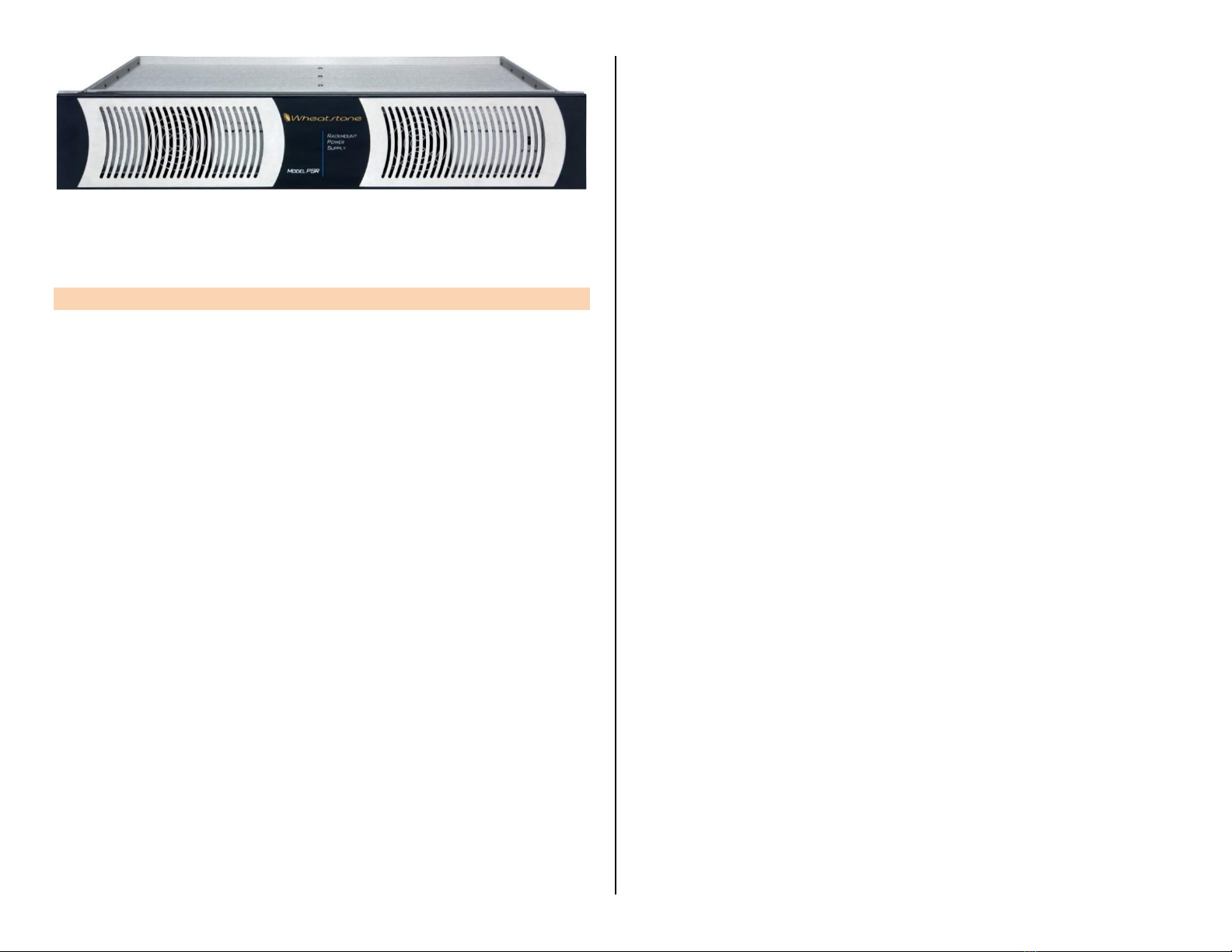
Figure 1-3 PSR Rack Mount Unit for two Power Supplies
Arcus Installation Kit –A USB flash drive, with PDF documentation files,
and the Wheatstone application installer programs, ships with Arcus.
ARCUS OVERVIEW
Arcus is Wheatstone’s flagship television console. It incorporates the
same IP audio innovations as Wheatstone’s AoIP radio consoles and Blades
while maintaining the processing power found in our other TDM-based TV
consoles. Arcus is available in various frame sizes from the Arcus-16 with
sixteen channel faders on up to an Arcus-48 with forty-eight channel
faders. All this control power fits into a compact frame that’s only 46" (117
cm) wide frame for the Arcus-16, or 74" (188 cm) wide for the Arcus-32.
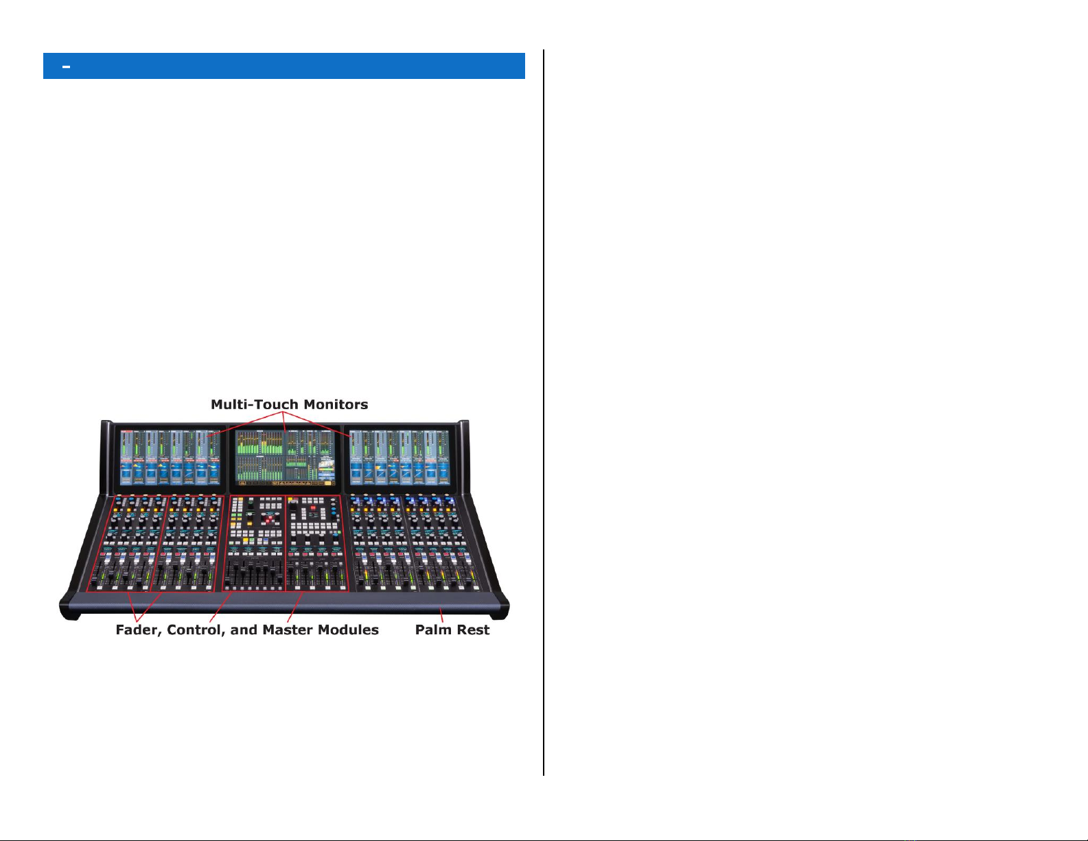
The console’s three main hardware components: Arcus Surface,
Gibraltar Mix Engine, and Surface Power Supply, along with the
optional Stagebox I/O Interface, are all FCC and CE certified.
The Arcus Surface is a compact audio-for-video controller. The fader
channel strips are mounted in Fader Modules which have four fader
channel strips. Each channel strip has a motorized fader, twenty control
buttons, six rotary encoders, and three color OLED displays. The channel
strip controls, along with the controls on the Master and Control Modules,
control the operation of the Gibraltar Mix Engine’s DSP, which contains the
Mixing and signal processing power for the Arcus’s input channels, Master
outputs, Submix groups, and VCA groups. EQ and Dynamics processing
are also available on every input channel along with monitoring controls
for the control room and three broadcast studios.
Designed for use in on-air studios, production suites, and remote
applications, the channel faders have ten layers of control, each with two
pages, to allow for control over even the most complex productions. One
can save and recall configurations for multiple shows and applications on
USB flash drives for instant console setup. All faders are motorized so their
physical positions quickly jump to their settings on each layer and page.
The Arcus integrates seamlessly with all major production automation
systems since it’s powered by Wheatstone’s award-winning WheatNet-IP
(WNIP) audio network, an AES67- and ST 2010-30-compatible IP audio
ecosystem, which allows for on-line Mixing, audio processing, and virtual
development tools including support for direct connection of SIP/VoIP and
codec appliances.
Arcus can access any resource connected to the facility’s WNIP network
using hardware fader channel controls or XY selector on the Control
Module, or thru software XY selectors on the main monitor. Since all Arcus
monitors are touchscreen, a row of intuitive View Select buttons along the
bottom of the main monitor allow one to quickly display various status and
control screens to adjust EQ and Dynamics, set up talkbacks, configure
Mix-minus feeds and bus matrices, assign mic muting and AutoMix group
control, and manage console sources and destinations.
Every fader channel has three OLED displays to show relevant channel
status and for user-set channel control functions. Another eleven OLED
displays on the Control and Master Modules show status and/or levels for
Aux, Sub Mix, or VCA groups, master outputs, monitor outputs, pane and
delay settings, source selection and levels, and talkback destinations.
Arcus’s I/O is entirely through the WNIP network so there are no
limitations regarding fixed connection points on the console chassis itself
since there are none! The Arcus Surface can access any source on the
network, and any channel can connect to any audio source or destination,
using any preferred audio format, at any time—regardless of whether it’s
HD/SDI, AES, MADI, AoIP, TDM, or analog. Unrestricted routing means
any source can be assigned to any channel, as needed. The days of having
to block out channels, based on input type, is a thing of the past, as is
having to repurpose inputs because of physical chassis limitations.
The Gibraltar Mix Engine can be mounted within the Mix room or in
any convenient rack within 330’(100 m) of the Arcus Surface (an optional
Fiber Interface allows for much longer connection distances). Two Mixer
Links (primary & secondary) connect the Surface to the Mix Engine. The
Mix Engine incorporates a WheatNet-IP (WNIP) interface, with a gigabit
Ethernet jack on a GBR card, to stream audio between the Arcus and the
other WNIP devices on the network.
The Mix Engine’s CPU includes DARS I/O to synchronize the Mix engine
with an in-house 48 kHz reference, although these days more often the
network will have a PTPv2 master clock, networked with the WNIP system,
to synchronize the Arcus to a 48 kHz sample rate to synchronize with your
video equipment and ST 2010-30- and AES67-compatible devices.
Each Arcus ships standard with a single output Surface Power Supply
(SPS-432), shown in Figure 1-3. It includes an IEC AC cord and a 16-foot
DC cable with locking connectors to connect the supply to the rear module
DC IN jack on the Arcus Surface.
The Arcus console ships with a factory default configuration so it can be
powered up and used straight out of the shipping crate. The default
settings are easily changed once the console is physical installed and
networked with one or more Wheatstone Blades or the Stagebox I/O
Interface to supply audio I/O for the console. The Arcus can then be
configured for use in a newsroom, production suite, remote van, sports
venue, or any number of other applications, using the two Windows PC
apps included with the console: Arcus Surface Setup and Navigator,

8
and/or by using the touchscreen controls. Chapter 3, starting on page 15,
covers how to use the supplied apps to configure your Arcus console.
Arcus Accessories
Most WheatNet-IP (WNIP) system peripheral devices can be networked
with the Arcus console. Here’s a sampling of the devices available: WNIP
TS-22 Talent Stations for monitoring and talkback, WNIP button control
panels, like the SS-series of rackmount panels with scriptable buttons and
color OLED displays, Wheatstone GP (General Purpose) control panels,
Vorsis audio processors, WNIP-compatible peripherals available from
Tieline, Eventide, and other vendors, and any PC or audio server running
the WNIP AoIP audio driver.
Several WNIP system apps (PC-XY, Meter App, and ScreenBuilder) can
also be used with the Arcus console since it supports ACI (Automation
Command Interface). Wheatstone’s ScreenBuilder app can be used to build
custom screens for remote control of many Arcus functions.
Stagebox I/O Interface (4RU, FCC and CE certified) –Designed for use
on a stage, newsroom, and other location where quick reconfigurations of
mic and line inputs and outputs may need to occur. Each Stagebox has 32
mic/line inputs on XLR jacks, eight AES inputs on BNC jacks, 16 analog
line outputs on XLR jacks, and eight AES outputs on BNC jacks. It also has
one 15-pin D-Sub LIO Logic jack with 12 GPIO logic ports. All connections
are on the front panel of the rack mounted device. Two Gigabit Network
ports, using latching RJ45 jacks, allow for redundant networking of the
Stagebox with the WNIP network.
WheatNet-IP Blades (1RU, FCC and CE certified) –Any model WNIP
Blade can be networked with the Arcus console to add rackmount I/O
anywhere in your plant. There are dozens of Blade models available to
interface just about any type of audio format including Blades with all or
Mixed analog and AES, MADI, or SDI (one SDI Blade can de-embed up to
four SDI inputs). Most Blades have local I/O for 8 x 8 stereo audio signals
and 12 GPIO logic ports on two RJ45 jacks. Most models include the DSP
to host a pair of software Utility Mixers, for quick on-the-fly Mixes, or to
function as an AES67 translator for networking AES67 audio devices with
the WNIP network.
WNIP Network
Arcus consoles “talk WheatNet-IP” which is an Audio-over-Internet
Protocol (AoIP) abbreviated as WNIP. This protocol allows an almost
unlimited number of devices: Arcus consoles, Stagebox I/O Interfaces,
Blades, and other WNIP-compatible devices like PCs and audio servers
using the WNIP audio driver, to share their resources over an AoIP
network that’s both AES67- and ST 2110-30-compatible.
The Arcus Surface’s Host Controller, the Mix Engine’s CPU and GBR
cards, and each Blade and/or Stagebox used for audio and logic I/O, are
networked using one or more AoIP-compatible gigabit Ethernet switches.
Each WNIP device connects to an access port on a gigabit switch using a
straight-thru CAT5e/CAT6 cable which can be up to 330 feet (100 meters)
in length. Multiple network switches can be connected using Trunk Ports to
expand the network’s range, or to create a star topology by connecting
WNIP devices in each studio to a local in-studio switch, which then
connects using a Trunk Port to a main gigabit switch in the Technical
Operations Center (TOC).
Contact Wheatstone sales or support or visit the Wheatstone.com
webpage (Support & Downloads > Compatible Switches for WheatNet-IP)
for a list of recommended network switches. PDF file with configuration
and setup info on many popular switch models are also available.
Appendix A provides additional details about creating a WNIP network.
Because Arcus consoles support WNIP,remote control and monitoring of
the console and just about any point in the WNIP network are available
using various software apps. Most automation vendors support the WNIP
system and specifically ACI (Automation Control Interface) which allows
most existing equipment to be networked with your Arcus console for both
audio streaming and system control by adding a WNIP audio driver to each
PC or server.
Arcus consoles also support WNIP SLIO (Software Logic I/O) which
allows playback systems, talent panels, script engines, and GPIO ports to
send/receive logic commands over Ethernet. To interface “old school”
GPIO devices that don’t support WNIP SLIO each I/O Blade and the
Stagebox have 12 hardware LIO (Logic Inputs/Outputs) ports.

9
ARCUS SPECIFICATIONS
All dimensions: Height x Width x Depth
Surface Dimensions
Arcus-16 = 14.2”(36 cm) x 43" (109 cm) x 29.4" (75 cm)
Arcus-24 = 14.2”(36 cm) x 56.15" (142.6 cm) x 29.4" (75 cm)
Arcus-32 = 14.2”(36 cm) x 69.5" (177 cm) x 29.4" (75 cm)
Arcus-40 = 14.2” (36 cm) x 82.75”(210 cm) x 29.4" (75 cm)
Arcus-48 = 14.2” (36 cm) x 96”(244 cm) x 29.4" (75 cm)
Rack-mounted Device Dimensions
Gibraltar Mix Engine (4RU): 7”(17.8c m) x 19" (48.3 cm) x
16" (40.6cm). Allow for 18” (45.7cm) of rear clearance for cabling.
Allow 2RU to mount the fan module below the Mix Engine and to mount a
blank module above the Mix Engine.
PSR Rack Case (2RU): 3.5" (8.9 cm) x 19" (48.3 cm) x 16.5” (42 cm)
Allow for 3” (7.6 cm) of rear module clearance for AC and DC cables.
Stagebox (4RU): 7” (17.8 cm) x 19" (48.3 cm) x 11" (28 cm)
Allow for 3” (7.6 cm) of rear module clearance for the IEC AC cord.
Power Supplies
Type: Switching
AC input: Detachable IEC cords
AC input: 90-240 VAC, 50/60 Hz
Surface Supply Output: +32 VDC @ 3 amps
Gibraltar Supply: Slide-in, field replaceable
Power Requirements
Gibraltar Mix Engine: <90 watts at 120 VAC / 60 Hz
Arcus Surface & Supply: <80 watts at 120 VAC / 60 Hz
Stagebox: <60 watts at 120 VAC / 60 Hz
Environment
Ambient Operating Te mperature: > 104°F (40°C)
Cooling: Arcus Surface and Stagebox I/O Interface are convection cooled.
The Gibraltar Mix Engine comes with a 1RU fan module which must
mount directly below the Mix Engine. The SPS-180R and SPS-432 power
supplies each have a built-in cooling fan.
We recommend leaving at least one rack space open above the Mix
Engine and Stagebox to allow for heat radiation from those units.
Wheatstone reserves the right to change specifications without notice or
obligation.

10
WARRANTY STATEMENT
LIMITED WARRANTY BY WHEATSTONE CORPORATION
1. All equipment sold and shipped to final destinations within the USA and its
possessions are warranted for one (1) full year from the date of purchase
against defects in material and workmanship. All equipment sold and shipped to
final destinations outside the USA and its possessions are warranted for one (1)
full year from the date of purchase against defects in material and workman-
ship.
All repairs to maintain the unit at original specification will be made at no
charge to the original purchaser except for shipping and insurance costs which
are to be prepaid by the owner to the factory in the event the unit cannot be
serviced by an authorized Wheatstone Corporation dealer.
2. This Warranty is subject to the following restrictions and conditions:
a) The owner must have filled out the enclosed Warranty Card and returned
it to Wheatstone Corporation; or, at the time of servicing, the owner must
provide proof of purchase from an authorized Wheatstone Corporation dis-
tributor or dealer.
b) This Warranty is valid for the original purchaser on the unit. Parts used for
replacement are warranted for the remainder of the original warranty pe-
riod. Repair or replacement is at the discretion of Wheatstone Corporation
and is the exclusive remedy hereunder.
c) This Warranty DOES NOT apply to damage or defects resulting from abuse,
careless use, misuse, improper installation, electrical spikes or surges, or
alteration, repair, or service of the unit or equipment by anyone other than
Wheatstone Corporation or its authorized distributor or dealer.
d) This Warranty is void if the serial number has been removed, altered, or
defaced.
e) This Warranty DOES NOT cover loss or damage, either direct or indirect,
arising out of the use, or inability to use this unit, or for shipping or trans-
portation costs to Wheatstone Corporation or its authorized distributor or
dealer.
f) Wheatstone Corporation reserves the right to modify or change any unit in
whole or in part at any time prior to return delivery in order to incorporate
electronic or mechanical improvements deemed appropriate by the
Wheatstone Corporation but without incurring any responsibility for modi-
fications or changes of any unit previously delivered or to supply any new
equipment in accordance with any earlier specifications.
g) THERE ARE NO OTHER WARRANTIES, EXPRESSED, IMPLIED, OR STATUTO-
RY, INCLUDING ANY WARRANTIES OF MERCHANTABILITY OR FITNESS
FOR A PARTICULAR PURPOSE. IF, FOR ANY REASON, AN IMPLIED OR
STATUTORY WARRANTY CANNOT BE DISCLAIMED, SAID WARRANTY IS
LIMITED TO THIRTY (30) DAYS FROM THE DATE OF PURCHASE. WHEAT-
STONE COPORATION IS NOT RESPONSIBLE FOR ELECTRICAL DAMAGE,
LOSS OF USE, INCONVENIENCE, DAMAGE TO OTHER PROPERTY, OR ANY
OTHER INCIDENTAL OR CONSEQUENTIAL DAMAGE, WHETHER DIRECT OR
INDIRECT, AND WHETHER ARISING IN CONTRACT, TORT, OR OTHERWISE.
NO REPRESENTATIVES, DEALERS, OR WHEATSTONE PERSONNEL ARE AU-
THORIZED TO MAKE ANY WARRANTIES, REPRESENTATIONS, OR GUARAN-
TIES OTHER THAN THOSE EXPRESSLY STATED HEREIN.

11
2 ARCUS HARDWARE INSTALLATION
he Arcus Surface is normally set onto a countertop with
its eight rubber feet holding it in place. The footprint for
the Arcus-16 is 43" (109 cm) wide, while the Arcus-32 is
69.5" (177 cm) wide. For larger frames see Surface
Dimensions on page 9. All frames are 29 3/8” (75 cm)
deep, from the front of the palm rest to a point below the
top of the angled monitor section. The top of the Surface’s touchscreen
“monitor bridge” is 14.2”(36 cm) above the countertop .
The Surface Power Supply Rack requires 2RU of rack space within a
few feet of the Surface. The SPS-432 slide-in power module has a cooling
fan, so no extra vent or blank panels are required. A 16-foot DC cable
connects each power module to the rear of the Arcus Surface.
The Gibraltar Mix Engine requires 6RU (10.5”) of rack space: 4RU for
the Mix Engine, plus 1RU for the included fan module which mounts
directly below it, and another 1RU for a blank or vented panel mounted
above the Mix Engine. Two customer-supplied crossover CAT5 cables, of
up to 300’ (100 m), interconnect the Mix Engine and Surface. Since there
are no audio or logic connections on the Mix Engine, its rack mounting
location is non-critical. Two customer-supplied straight thru Ethernet
cables (CAT5e/CAT6), or three with the optional redundant CPU card,
connect the Mix Engine to access ports on a WheatNet-IP (WNIP) system
network switch.
ARCUS SURFACE PLACEMENT
The Arcus Surface cable connectors are on the vertical section of the
lower rear chassis, near the right-rear corner (as viewed from the board
operator’s position). Figure 2-1 shows the connections for the DC cables
from the power supply and the crossover and straight-thru Ethernet cables
connecting the Mix Engine and WNIP system Ethernet switch ports.
How one makes these connections is covered in detail in later sections of
this chapter. This section covers preparing the countertop and drilling one
or two countertop holes, so the cables can be cleanly dressed up through
the countertop, prior to setting the Surface into its permanent position.
The Surface connectors are located directly below the touchscreen
monitors, hidden by a lower rear cover panel. Although one could leave
this rear cover off and just run the power and Ethernet cables so they
drape over the rear of the cabinet, drilling one or two small cable access
holes thru the countertop, which will also be hidden by the rear cover, is
the recommended method.
Figure 2-1 Surface Cabling, rear chassis, partial view
Figure 2-2 shows the Surface chassis dimensions and cable access area.
A dashed rectangle outlines an area where one or two small thru-holes can
be drilled for cable access from below the countertop.
The vertical section of this part of the chassis is detailed in Figure 2-1. It
is 23.25” (59 cm) behind the front of the palm rest. Since the DC cables
are much stiffer than Ethernet cables, we recommend drilling one 1.5” or
2” hole about 6” to 8” to the right of the DC In 2 jack (as viewed from the
rear) to allow the DC cable, which has a right-angle connector, to be
brought up thru the countertop to easily fasten to the DC IN 1 jack.
Alternately, drill two smaller access holes (3/4” or 1”), as shown in Figure
2-2. One for the DC cable, the other for the Ethernet and Link cables.
Figure 2-2 Surface, Lower Chassis
(showing cable access and countertop mounting holes)
If the Surface must be secured to the countertop, the eight rubber feet
on the bottom of the chassis can be removed using a #2 Phillips
screwdriver. Set the Surface into position. Remove the left-most and right-
most Modules (four #1 Phillips screws per module), then lift each module
up to unplug one CAT5 cable per module and set those modules aside.
T

12
Mark the countertop using the four threaded chassis holes, near the front
and rear corners.
Note: Be sure to keep track of which removed module goes into
which position when both are Fader Modules since they may
appear identical but their physical positions within the Surface are
identified by board-mounted DIP switch settings. This means if you
swap the two Fader Modules their fader channel numbers will be
out of order. A minor oops since one would just need swap the two
modules to rectify the issue.
Once the four holes are marked, move the Surface safely out of the way
and use a #16 drill bit to drill completely thru the countertop and
supporting substrate. If the countertop surface material is laminate, use a
new 1/4” drill bit to drill just thru the laminate to ensure the mounting
screw threads won’t touch the laminate as they are fastened to prevent
future laminate cracks from forming.
Use a lock washer and one or more oversize washers to support the four
#8 machine screws or bolts that will need to extend up thru the substrate
and countertop material to fasten into the four threaded holes in the
chassis. Dry fit a machine screw/bolt into one hole, making sure its end
does not extend more than 3/8” (9.5mm) above the countertop.
Set the Surface back into position and evenly tighten the four #8
machine screws/bolts. Tighten them only enough to firmly hold the
Surface to the countertop. Reinstall the two modules (set them onto the
front rail and plug in their CAT5 cable then set them onto the upper rail
and reinstall their Phillips screws.
Power Supply
The Arcus Surface is powered by a separate 2RU (3.5”) rackmount PSR
Rack Unit (Figure 2-3). One SPS-432 slide-in supply is included with the
Surface. A second supply (optional) can be added for redundant power.
Mount the PSR Rack Unit into a 19” equipment rack located near the
Surface. A 16-foot (4.88 m) DC cable connects the supply to the Surface.
Do not mount any high gain audio equipment near the power supply since
this could lead to magnetic interference with that equipment.
Once the supply is mounted, plug in the factory-supplied DC cable to the
DC OUT jack and fasten the 8-pin connector’s screws to secure it place.
The other end of the cable has a two-pin right-angle connector. Route it
to, and plug it into, the DC IN 1 jack on the rear of Surface. Tighten its
mounting screws to securely fasten that end of the DC cable.
Note: Since the power supply does not have a power switch, do
not plug in its AC cord until advised to do so once all other cabling
has been connected to the Surface, as outlined in the Energizing
the Arcus section on page 14.
The power supply has a 3-wire grounded IEC AC cord. The cord should
only be plugged into a “clean” or isolated AC circuit exclusively used to
power the control room audio gear. In the USA, this is an gold-colored AC
outlet which indicates it has an isolated AC ground. If this type of outlet is
not available, the power supply (and the Gibraltar Mix Engine) should only
plug into AC circuits with other audio equipment. Lighting, air-conditioning,
and other non-audio equipment or machinery should not be on the same
circuit the console components are using. Regardless of the type of AC
circuit used, the ground wire for the AC outlet must always be tied to the
central AC system’s technical ground.
Use of an Uninterruptable Power Supply is also recommended.
Redundant Supply Installation
A redundant supply includes a second SPS-432 slide-in DC supply, a DC
cable, and an IEC AC cord. Slide the supply module into the PSR from the
front and fasten it into place using the thumbscrew fastener.
Once mounted, connect the supplied DC cable to the DC OUT jack on the
rear of the redundant SPS-432 supply and tighten its mounting screws.
Route the DC cable to the Surface and plug it into the DC IN 2 jack. If
available, plug the two supplies into AC outlets on different circuits. The
use of a UPS on both supplies is always recommended.
Figure 2-3 Rear View, PSR rack with two SPS-432 DC Supplies
GIBRALTAR MIX ENGINE
The Gibraltar Mix Engine has no user controls, nor are there are any
audio or logic connections. Its front panel is hinged to allow service access
to its plug-in cards. Figures 2-4 and 2-5, on the following page, show the
Mix Engine’s front and rear views. Figure 2-7, on page 14 outlines the
various Arcus Surface and Gibraltar Mix Engine connections.
Two crossover CAT5 cables (customer-supplied) of up to 300 feet
(100m) connect the two Link ports on the Surface to Ports C and D on the
QAT card in the Mix Engine. Mount the Mix Engine in any convenient rack
location. The fan module (included) must mount immediately below the
Mix Engine, and at least one blank panel must be mounted immediately
above the Mix Engine to allow for proper air-flow thru the Mix Engine.
The Mix Engine is networked with other WheatNet-IP devices using one
or more gigabit Ethernet switches. Connect a straight-thru CAT5e/CAT6
cable (customer-supplied) from the GBR port to a network switch access

13
port to carry streaming audio to/from the Arcus to other WNIP devices on
the network. A CAT5/5e/6 Ethernet cable can connect the CPU card’s
Ethernet port to a switch access port for communications traffic.
Figure 2-4 Gibraltar Mix Engine, Front View
Figure 2-5 Gibraltar Mix Engine, Rear Module
If the Mix Engine must be located more than about 300 feet from the
Surface, optical fiber must be used to connect the two devices. A QOT
fiber interface card must be used in lieu of the standard QAT card. A QOT
card has fiber rather than “copper” (RJ45) connectors. If this is done in the
field, board mounted switches on the Surface Host card, to switch from the
RJ45 jacks to the fiber jacks, must be changed. If the Arcus was ordered
with a QOT card, the switches are already set to use the fiber jacks rather
than the RJ45 jacks.
STAGEBOX
The Stagebox is an optional I/O Interface available for use with the
Arcus. It’s networked along with the Mix Engine and Arcus Surface on one
or more gigabit switches, along with other WNIP Blades and consoles to
share resources in a facility-wide WheatNet-IP network.
A Stagebox (Figure 2-6) has 32 mono/16 stereo mic/line inputs, 8 stereo
AES inputs, 16 mono/8 stereo analog, and 8 stereo AES outputs so it can
function as a complete audio I/O interface for the Arcus console when used
in a stand-alone application like a remote truck or a live venue. When this
is done, one small gigabit switch would network the Stagebox, Mix Engine,
Surface, and automation system server together.
The Stagebox outputs can be used to drive powered monitor speakers
and in-ear pieces while the mic-line inputs can be configured for a mix of
mic inputs and line-level inputs. Inputs and outputs are easily reconfigured
for any mix of mono, stereo, and 5.1 surround signals.
Figure 2-6 Stagebox Audio & Logic I/O, Front Module
FINAL SURFACE CONNECTIONS
The DC IN and Surface Link connections were covered in the Power
Supply and Gibraltar Mix Engine sections, so there is one final Surface
connection to be made: networking the Surface’s Main Host Card to an
access port on a gigabit Ethernet switch. A summary of the connections for
all Arcus components is shown in Figure 2-7 on the following page.
If the optional Backup Host Card is present, then it’s also networked to
an Ethernet switch port. These Host card connections allow the Surface to
be remotely configured using the Arcus Surface Setup app, which typically
runs on a system admin PC networked with the WNIP system. The various
other ports on the Host cards are typically not used.
Note: There are two USB ports: CLIP and USER located at the top
of the right-most column of controls on the Master module. The
CLIP port is available for a board operator to plug in a USB flash
drive containing 48 kHz audio files in .WAV format and/or M3U
playlist files to playback audio on any channel using the Clip Play
View controls on the main touchscreen. The USER port allows a
board operator to save and load console Events to quickly
reconfigure the Surface for a specific show or application using the
Events View on the main touchscreen.

14
ENERGIZING YOUR ARCUS CONSOLE
Assuming the Arcus Surface is set into position, its power supply is
mounted, its DC cables are fastened to the connectors on the power
supply and Surface, and the Mix Engine is mounted and linked with the
Surface and with one or more WNIP network switches. The IEC AC cords
can be plugged in to energize the switches, the Surface’s power supply,
the Gibraltar Mix Engine, the Stagebox, and other I/O Blades.
It takes roughly two minutes for the Surface and Mix Engine processors
to complete booting and load their current configuration settings. During
this time, the Surface’s touchscreens and OLED displays show various
information as the Host controller and other boards within the Surface,
and the DSP and other cards within the Mix Engine, complete booting up.
The faders travel to full off when the Surface is first energized. Once the
Surface and Mix Engine complete booting, the faders jump up to the
positions they were in, on the active Layer, when the Surface was powered
down. On a new console this will typically leave most, if not all, faders at
full off. The channel OLED displays show their current input sources
(NoSource on every channel on a new console). The Arcus is now ready
for use.
Note: To de-energize the Arcus Surface, unplug the power
supply’s IEC AC cord (or cords) from either the supply or the AC
mains. DO NOT de-energize the Surface by disconnecting the DC
cable from the Surface or the power supply.
Once the Surface completes start up, a Surface Information window may
be left open in the middle of the touchscreen. To close that window, tap
once on the ? button, in the lower right corner of the main touchscreen
monitor. The ?button’s yellow background turns black. When the ?button
has a black background, tapping it opens the Surface Information window
which lists firmware revisions for the Arcus components. In that window,
tap the Alarms button to show Surface and Mix Engine alarms or tap the
Stats button to show the Touchscreen’s CPU Statistics window.
If an alarm is detected, an Alarms window appears on the main
touchscreen and the ?button changes to a yellow triangle with an !.
Tapping that button closes the Alarms window but the ! button remains
shown as a yellow triangle until the alarm condition is cleared, at which
time the normal rectangular ?button is again shown on the touchscreen.
Figure 2-7 Arcus Surface, Mix Engine, and Power Supply Standard Interconnections

15
3 ARCUS APPS AND CONSOLE CONFIGURATION
he Arcus console’s factory-default settings allow it to be
powered up and used straight out of the box. Many
common channel settings can be viewed and changed
using the Surface controls on the channels and on the
channel touchscreens, but to change console-wide
settings, and to rename the generic factory-assigned
source names to names for your actual signals, two Windows®software
apps: Arcus Surface Setup and Navigator are used. Both apps are
included on a USB flash drive that ships with the console. They can be
installed on any Windows®7-10 PC networked with the Arcus and its I/O
interfaces (the Blades and/or Stageboxes). These apps can alternately be
downloaded from a Wheatstone file management site. Email Wheatstone
Here’s a list of the default IP addresses, device names, and ID numbers,
assigned at the factory for the standard cards, in black type, and for the
optional cards, in blue type, used in the Arcus Surface, the Gibraltar Mix
Engine, and the Stagebox:
Stagebox (Blade 50): 192.168.87.150
Mix Engine GBT card: 192.168.87.241
GBT Secondary card: 192.168.87.242
Mix Engine Main CPU (Blade 64): 192.168.87.164
Backup CPU: 192.168.87.165
Arcus Surface Main Host Controller: 192.168.87.196
Backup Host Controller: 192.168.87.197
Note: Before networking a new WheatNet-IP (WNIP) device with
an existing WNIP network, verify that the device’s IP address and
ID number are available for use. Duplicate IP addresses and/or
Device ID numbers will cause network communications issues.
Arcus IP addresses can be changed to use other Class B or C subnets
but, if possible, we recommend leaving them on the default 192.168.87.0
subnet to simplify system troubleshooting and future system expansion,
since new Wheatstone AoIP devices are assigned a fixed IP address within
this subnet from the factory. If your WNIP system is using another subnet,
every default IP address on every new WNIP device will need to be
changed to fall within that subnet prior to being networked with your WNIP
system.
The two primary Arcus software applications: Arcus Surface Setup and
WNIP Navigator, are typically installed on an admin PC running
Windows®(Win7-10 PCs and equivalent servers are supported). The
admin PC must be networked with the Mix Engine, the Arcus Surface, and
the Stageboxes and/or Blades with the console’s audio and logic I/O, using
a fixed IP address within the WNIP system’s subnet. We recommend
setting the admin PC to 192.168.87.21 with a subnet mask of
255.255.255.0. Connect the PC’s NIC to a port, configured for switchport
mode access, (e.g., an access port) on any gigabit Ethernet switch in the
WNIP system.
To ensure that the Wheatstone apps are properly installed, network the
PC with the WNIP system prior to installing the apps. Install each app by
right-clicking on the installer icon, or on its file name, and selecting Run as
Administrator. Accept the default installation settings. If a previous version
of either app was installed on that PC, the installer automatically uninstalls
the previous version prior to installing the new version. Licensing and app
configuration settings are maintained in the new version.
A shortcut icon for each app is placed on the desktop. On a Win 7 PC’s
Windows Start menu, the Navigator app is in the WheatNet IP folder, and
the Arcus Surface Setup app is in the WheatNet IP Arcus folder. On a Win
10 PC all Wheatstone apps are found under the Wheatstone category.
Note: Wheatstone apps communicate with the WNIP devices using
multicast messaging. If you find the apps do not see any WNIP
devices—especially if they were installed prior to networking that
PC with the WNIP system, verify that the app is using the NIC
connected to the WNIP system. If that is correct, then turn off
Windows Firewall or add Navigator and the Surface Setup apps to
the list of programs allowed thru the Firewall.
Navigator is a licensed application. A Navigator license is required to
unlock all of Navigator’s features. Basic functions like making crosspoints,
editing signal names and their formats, and assigning logic can all be done
using an unlicensed copy of Navigator, but you’ll see a lot of “nag pop-
ups” like this:
The section on using Navigator begins on the following page. Using the
Arcus Surface Setup app is covered in its own section, beginning on
page 31.
T

16
NAVIGATOR
Navigator is initially going to be
used to name and configure
signals connected to the
Stageboxes and Blades which are
networked with the Arcus. These
type of functions don’t require a
Navigator license, but one is
required to access all of
Navigator’s features. Contact your
Wheatstone dealer or sales
person, for pricing.
These are Navigator’s main
features and functions:
•View and update the WNIP
operating system on the
networked Mix Engines,
Stageboxes, and Blades.
•Backup and restore system
configuration files.
•Set system-wide settings like
the system sample rate, date
and time, device colors used in
the app, etc.
•Assign logic functions to the 12
“hard” and 128 “soft” LIOs
(Logic Inputs/ Outputs)
available on each Blade and
Stagebox.
•Connect system signals using an
X-Y Crosspoint Grid. The
crosspoints can be saved to files
for later recall.
•Create Salvos to quickly connect multiple signals by using an ACI
command or a programmable button on the Arcus Surface.
•Set Associated Connections to control audio and logic connections based
on system activity.
•Evaluate and troubleshoot the WNIP system including monitoring the
audio at any input or crosspoint, and on most destinations.
To start Navigator, double-click its desktop icon or, from the Start Menu
on Win10 PCs, select All Programs > Wheatstone > WheatNet IP
Navigator. On a Win7 PC, select All Programs > Wheatstone >
WheatNet IP > WheatNet IP Navigator.
The app opens showing the System Crosspoint
Grid (Figure 3-1). A Login popup also appears. When
first using the app, just click OK to close the popup
since no password is set by default. We do
recommend setting a password—especially when
Navigator is run on PC in a studio since an
unauthorized user could cause unexpected audio
connection changes and make other undesired
system changes.

17
Figure 3-2 Signal
Monitor Pop-Up Win-
dow
System Tabs
The System > Crosspoint tab is shown when the app starts. Clicking
on a Blade, a Surface, or another icon in the System Dock changes what
tabs are displayed. Clicking on a different System tab, or on a different
page tab, will also change what’s displayed. To re-display the Crosspoint
Grid, click the System icon in the System Dock, or the System page tab,
then click the Crosspoint tab. A separate Crosspoint Grid floating window
can also be opened by clicking the X Point window selector.
The Crosspoint grid shows system sources on the horizontal axis and
system destinations on the vertical axis along with icons indicating
connected signals in an XY grid. The signal name colors match the device
icon colors in the System Dock. These can be changed using the Blade
Preferences section of the System > Preferences tab.
Connected audio signals are shown by round dots with the dot colors
normally indicating basic signal level: purple = no or a low signal, green =
a normal level signal, red = a high level signal. A single small dot indicates
a mono source-destination connection. Two dots at a 45° angle indicate a
stereo source connected to a stereo destination. If there are two dots
stacked vertically the source is mono, but the destination is stereo.
Likewise, two horizontal dots indicate a stereo source is connected to a
mono destination. A large circle indicates a connection between a 5.1
source and a 5.1 destination.
A small green square indicates a logic-only crosspoint. A horizontal red
line indicates a destination that’s locked, which can be done manually,
using the destination context menu item: Lock Signal, but it also occurs
automatically occur when a Surface channel is turned on, and the option
Lock Destination When On, is checked in the Arcus Surface Setup app
(Surface Options > General page tab).
Connecting Signals
As you mouse over the grid, purple X-Y crosshairs point to a source and
a destination for easy identification of which signals will be connected if
the Crosspoint Target is “clicked” in the grid. Clicking on a crosspoint adds
an icon to indicate that connection is now active. To disconnect a signal,
click on an active crosspoint to break the connection, silencing the
destination on an audio connection or turning off the logic on a logic
crosspoint.
Note: As a safeguard to prevent accidental connections or
disconnections you can require the CTRL key be pressed when
clicking the grid to make or break a crosspoint. This option is set in
the General section of the System > Preferences tab.
Destinations with a horizontal red line across the grid indicate they’re
locked from change since they’re actively in-use. However, a locked signal
can be unlocked by right-clicking on the Destination name and selecting
Unlock Signal from the context menu.
Note: Use caution when unlocking fader channel destinations.
Locking typically indicates channels that are currently on.
Monitoring the Audio
Right-clicking on an active crosspoint
connection, on a source name, or on a
destination name, brings up various context
menus, shown in Figure 3-1 on the previous
page. Selecting Monitor, Monitor Source, or
Monitor Destination opens a pop-up Monitor
window (Figure 3-2) which shows the Source
levels and, if that signal is connected to an
output, the Destination levels. A drop down
list in the Listen section allows you to choose
which PC audio destination to use to listen to
the signal. Click Listen to Source to listen to
the audio. Use the Volume control to adjust
your listening level.
This feature allows one to remotely monitor
the system audio by installing a remote
access app like TeamViewer on the admin
PC—and having a second NIC on that PC
that’s connected to the internet.
Salvos/Macros Tab
Clicking on the System > Salvos/Macros tab opens a display that
looks like an unpopulated Crosspoint grid. The difference is that this grid is
not “live.” In the Salvo grid (Figure 3-3 on the next page) you connect the
signals needed for a future show, event, or other console application.
These connections are automatically saved as a new Salvo, which means
that all crosspoints are made when that Salvo is later “fired” or taken.
Dozens of audio and/or logic crosspoints can be set and saved in dozens
of Salvos. Each Salvo begins life assigned a number (Salvo 1, Salvo 2, and
so on) which won’t mean much as time goes by, so you’ll want to rename
each Salvo you create so you’ll remember why it was created. Select the
Salvo in the drop down list, then click Rename. Even though you can enter
a name with an almost unlimited number of characters, only about 25
characters are shown in the Salvo drop down list. However, when selecting
a salvo to assign to a Spare button in the LIO tab, only the first eight
characters are shown so it’s best to limit the Salvo name to eight
characters, like: MorngRMT, SuperPre, or GrdnShow.
Click New to create a new Salvo with the name Salvo X (empty), with
Xbeing the next unused Salvo number. Any existing crosspoints are
removed so you have a clean slate. As soon as you make a connection
“(empty)” is removed from the name indicating that Salvo is now active.
There’s no Save Salvo button since the active Salvo is updated with each
edit you make on the Salvo grid.

18
When you select a Salvo from the drop down list, its crosspoints are
shown in the Salvo Edit Screen in read-only mode. The Details Dock also
lists the crosspoints in that Salvo by destination and source name. To
make further changes, checkmark the Editable option to allow crosspoints
to be added or removed.
Figure 3-3 Salvo/Macro Tab
To take the crosspoints in a Salvo, use the drop down list to select a
Salvo then click Fire. The crosspoints in that Salvo are immediately
connected—except for those going to locked destinations like channels that
are currently on. Those connections will not be made. To make those
connections, turn off the channel or unlock the destination, then fire the
Salvo again. Salvos can also be fired by assigning the Fire Salvo function
to a programmable button on the Master module.
Info Tab
This tab’s main use is to set the Clock Master’s sample rate, which can
be set to 44.1 or 48 kHz. For TV applications select 48 kHz. The other
section settings are typically left at their default settings unless AES67
devices will be networked with Arcus. This tab is where the AES67 master
clock source is set and sets whether AES67 sources and/or destinations
are shown in the System Dock. Navigator must have an AES67-PTP license
to access these enhanced Navigator features.
Note: A separate AES67-PTP License (which is gratis) must be
applied to Navigator before one can network AES67 devices with
the Arcus console. Click the “? About” Window Selector to open the
About Window. Click on Request AES67-PTP License to get a Seed
ID text string to email to Wheatstone Tech Support to obtain an
AES67-PTP license key file.
LIO Properties Tab
This tab allows the unconnected or not-true state of the User-set logic
functions (User 1–User 500) to be set for High, Low, or leave in the Last
State. The default setting is Low (Figure 3-4). This tab also shows the
settings for the pre-defined logic functions, but it doesn’t allow the settings
to be changed. The pre-defined logic settings which can be individually set
for high or low states when unconnected or not-true, by selecting Invert in
the LIO Settings window while assigning LIO or SLIO logic.
Figure 3-4 System Info Tab Details
Associated Connections Tab
This tab is used to create, view, and edit Associated Connections, which
are useful to automate console or system operations. An Associated
Connection consists of two parts: the Triggered Connection and the

19
Associated Connections. When a triggered connection is detected by the
host Blade, all the specified Associated Connections are then made. This
function is used to automate many complex system operations. For
example, in a shared talk studio, when the studio host mic is taken on a
specific fader channel (the trigger), the other mics and the studio monitor
and logic connections are then all connected to that console (the
Associated Connections). A very common use for Associated Connections
is to set up remotes to ensure the correct bus-minus or mix-minus signal
is always connected back to that remote when that remote’s codec is
taken on a fader channel, as shown in Figure 3-5.
Figure 3-5 Associated Connections Tab
A Trigger Connection is assigned by clicking Add… in the Triggered
Connections section of the tab to open the Add Triggered Connection
dialog box where a source and destination are selected. In the example
PHONE 1, when taken on channel 12, is the trigger. Click OK to add that
entry to the Triggered Connections list.
With that triggered connection highlighted, click the Add… button in the
Associated Connections section to open the Add Associated Connection
dialog box. Select the source and destination to be connected in response
to the trigger connection being made. In most cases you’ll want to
checkmark the Lock Override option. When checked, and the trigger
connection is detected, the selected source will be connected to the
destination even if another signal is connected and the destination is
locked. When Lock Override is not checked, the Associated Connection
would not be made if the destination is locked.
Multiple Associated Connections can be assigned to occur with a single
trigger connection. Once all Associated Connections are assigned, click the
all-important Apply button to tell the Blade with the Triggered Destination
to monitor the system waiting for the triggered connection to occur. When
it’s made (e.g., PHONE 1 is taken on channel 12) all the Associated
Connections assigned to that Triggered Connection are connected.
AES67 Visibility
This tab sets which WNIP signals are transmitted to AES67 devices and
which ones can receive AES67 device audio streams. This tab is not used
unless you’ve applied an AES67-PTP License to Navigator and have AES67-
compatible devices networked with your WNIP system. Signals are
selected as in the Visibilities tab in the Arcus Surface setup app (page 42
has signal selection details).
Figure 3-6 AES67 Visibility Tab
When a source is set as visible, their audio is then transmitted to the
Blade that’s functioning as the AES67 translation Blade so it can be
converted into an AES67 stream for transmission to an AES67 device.
Checking a lot of signals could thus cause audio streaming traffic issues
since, in a WNIP system, audio streams are only transmitted when a
source is connected to at least one destination. Thus, when a lot of
sources are selected, even though the network may be properly
configured, one could still run out of bandwidth to the AES67 Translation
Blade. The bottom line: select only those signals which you plan on
connecting to/from AES67 devices.

20
Meters Tab
This tab allows up to 64 meters to be created to show levels for WNIP
system sources and/or destinations. The only signals which you can’t
meter in this tab are AES67 signals and the Arcus Mix Engine’s
destinations (console fader channels and external monitor inputs).
Meters are displayed in eight rows of eight meters. Mono and stereo
signals take up one meter space while a 5.1 signal meter takes up three
meter spaces, as shown in Figure 3-7. The meter order is set by their
selection order so it’s best to group your selections between Source
Signals and Destination Signals. Also, when meters are removed—by
unchecking a signal in the Source or Destination Signals list, the remaining
meters are not rearranged so you’ll need to checkmark another signal to
meter to fill in any gaps in the meter rows.
Setting up meters in this tab can be especially useful when accessing the
system remotely since you can quickly see multiple signal levels on
different devices immediately, as opposed to selecting a Blade and then
viewing its Sources or Destinations tab to view signal levels.
This tab can also be set as a Floating Window by clicking the Float
button in the upper right corner. To re-dock the tab, click the Unfloat
button.
Figure 3-7 Meters Tab
Config Manager Tab
This tab (Figure 3-8) is used to backup or restore the entire system’s
configuration, a selected configuration setting for one Blade, or the system
crosspoints. It’s important to periodically save a system backup (especially
after finishing setting up a new system) so that all system settings are
saved in case they need to be restored due to a catastrophic system
failure, or if a disconnected device were to be deleted from Navigator,
which would mean the system couldn’t recover system information about
that device from any WNIP Blade.
In normal conditions, every Blade has the configuration information for
all other Blades so the system can recover any Blade’s configuration
automatically when a Blade is replaced, but having an off-line backup is a
good insurance policy so you can recover a Blade’s configuration if
automatic recovery cannot work.
The choices shown in this tab are affected by a setting in the
Preferences tab: Enable Advanced Controls. When it’s unchecked, you
have the selections shown in Figure 3-8. When that option is checked the
Current Crosspoint section adds a Save button so all the current
Crosspoint connections can be saved to a file for later recall. Press Restore
to select one of the crosspoint settings files. The crosspoint connections
are saved in: Documents > Wheatstone > Navigator > Connections.
Clicking Restore… opens a dialog box to select a saved crosspoint
connection file.
Figure 3-8 Config Manager Tab
When you save the current crosspoints, the file is named by the saved
date and time. Not very useful in the long term, so click on Restore to
open the list of saved crosspoint files and edit the just-saved file name by
an activity or daypart so the Restore function can then be used later as an
alternative to using a salvo—with one very important caveat: using
Restore Crosspoint overwrites locked signals—including ones locked
because that signal is currently on-air. This means a channel source could
suddenly change if the source is different than what’s currently connected,
whereas taking a salvo does not change sources on any locked destination,
like currently on-air channels.
Other manuals for ARCUS
1
Table of contents
Other Wheatstone Recording Equipment manuals

Wheatstone
Wheatstone A-6000 User manual

Wheatstone
Wheatstone TV 1000 User manual

Wheatstone
Wheatstone GSX User manual

Wheatstone
Wheatstone ARCUS User manual

Wheatstone
Wheatstone G-5 User manual

Wheatstone
Wheatstone E-5 User manual

Wheatstone
Wheatstone GSX Troubleshooting guide

Wheatstone
Wheatstone M-2 User manual

Wheatstone
Wheatstone SP-8 User manual

Wheatstone
Wheatstone D-8000 User manual