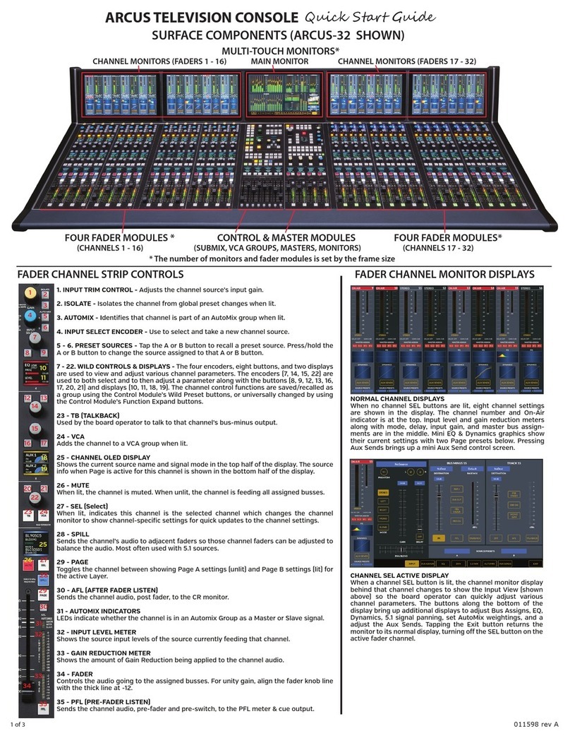
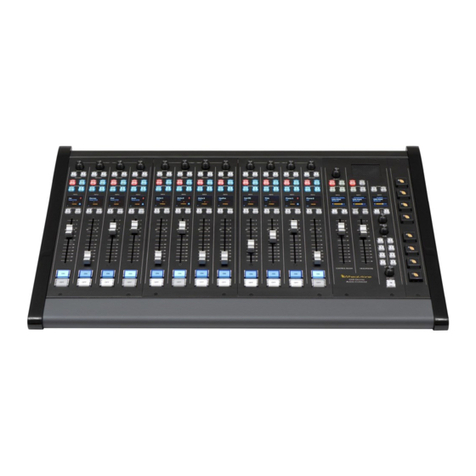
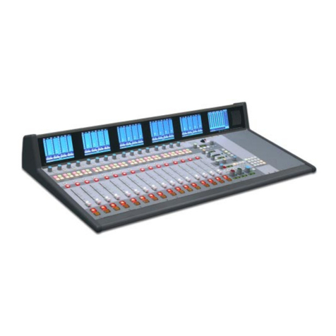
Wheatstone G-6 User manual

G-6 Digital Control Surface
TECHNICAL MANUAL
600 Industrial Drive, New Bern, North Carolina, USA 28562

WHEATSTONE CORPORATION
600 Industrial Drive
New Bern, North Carolina 28562
tel 252-638-7000 / fax 252-637-1285
G-6 Digital Control Surface Technical Manual - 1st EditionG-6 Digital Control Surface Technical Manual - 1st Edition
G-6 Digital Control Surface Technical Manual - 1st Edition
©2005 Wheatstone Corporation
G-6/March 2005

AA
AA
ATTENTIONTTENTION
TTENTIONTTENTION
TTENTION
RR
RR
READEAD
EADEAD
EAD MM
MM
M
EE
EE
E!!
!!
!
G-6 / March 2005
Attention!
FF
FF
Federal Communications Commission (FCC)ederal Communications Commission (FCC)
ederal Communications Commission (FCC)ederal Communications Commission (FCC)
ederal Communications Commission (FCC)
Compliance Notice:Compliance Notice:
Compliance Notice:
Radio FRadio F
Radio FRadio F
Radio Frequency Noticerequency Notice
requency Noticerequency Notice
requency Notice
NOTE:NOTE:
NOTE:NOTE:
NOTE: This equipment has been tested and found to comply with the
limits for a Class A digital device, pursuant to Part 15 of the FCC rules. These
limits are designed to provide reasonable protection against harmful
interference when the equipment is operated in a commercial environment.
This equipment, generates, uses and can radiate radio frequency energy
and, if not installed and used in accordance with the instruction manual,
may cause harmful interference to radio communications. Operation of this
equipment in a residential area is likely to cause harmful interference in
which case the user will be required to correct the interference at his own
expense.
!
This is Class A product. In a domestic environment,This is Class A product. In a domestic environment,
This is Class A product. In a domestic environment,
this product may cause radio interference, in which case,this product may cause radio interference, in which case,
this product may cause radio interference, in which case,
the user may be required to take appropriate measures.the user may be required to take appropriate measures.
the user may be required to take appropriate measures.
This equipment must be installed and wired properly in order to assure
compliance with FCC regulations.
Caution!Caution!
Caution!Caution!
Caution!
Any modifications not expressly approved in writing byAny modifications not expressly approved in writing by
Any modifications not expressly approved in writing by
Wheatstone could void the user's authority to operate this equipment.Wheatstone could void the user's authority to operate this equipment.
Wheatstone could void the user's authority to operate this equipment.

RR
RR
READEAD
EADEAD
EAD MM
MM
M
EE
EE
E!!
!!
!
G-6 / March 2005
IMPORTANT!
Cleaning the Acrylic Surface
An acrylic surface is a beautiful, lustrous material that is outstanding in
durability and break resistance. With proper care, it will retain its attractive
appearanceformanyyearstocome.Thiscareshouldincludeprecautionsagainst
scratchingorcontactwithobjectsofhightemperaturethatmightmarthesurface.
A few simple precautions will preserve the beauty of the acrylic.
• FIRST be sure the surface to be cleaned is powered off.
• NEVER spray or pour any liquid directly onto the surface.
• TO AVOID scratching these surfaces, use a soft brush or cloth to gently
brushawayanylargerdirtparticles.Alternatelythelargerparticlescanbeblown
from the surface with the use of canned air.
• USE a soft, clean lint free cloth or micro fiber cloth and clean lukewarm
water to clean the surface. For stubborn dirt and stains use a mild, nonabrasive
soap and water mixture with the gentle cleaning cloth. Use only light pressure
when cleaning. Avoid rubbing dirt or grit into the surface. Turn the cloth often
andreplacewithacleanclothfrequently.Drybyblottinggentlywithaclean,dry
cloth.
• AVOID using kleenex, paper towels, sponges or other coarse shop towels,
as these materials may contain abrasives that can scratch acrylic surface.
• DO NOT USE ketones, aromatics, esters, halogens, window cleaning
sprays, alcohol, kitchen scouring compounds, or solvents (such as acetone,
benzene, gasoline, carbon tetrachloride, or thinners).
Caution! Donotuseammoniabasedcleaningsolutionsastheycancausethe
surface to yellow, and became brittle and eventually cause structural damage to
the acrylic surface.
Wheatstonewillnotbeliablefordamageresultingfromimpropercleaning
and maintenance.
!

page Contents – 1
G-6 / Mar 2005
CONTENTS
G-6 Technical Manual
Table of Contents
Chapter 1 – General Information
Introduction ...................................................................................1-2
Control Surface Placement ..........................................................1-3
Power Supply ................................................................................1-4
Failsafe Dual Redundant Supply.............................................................................. 1-5
Energizing ................................................................................................................. 1-5
I/O Connections.............................................................................1-6
The Insulation Displacement Connector System ..................................................... 1-6
Wiring Procedure - Double Connection to One Pin.................................................. 1-8
Chapter 2 - Input Panel (IS-G6)
Controls and Functions................................................................2-2
Input Sources............................................................................................................ 2-2
SET Button................................................................................................................ 2-2
AUX........................................................................................................................... 2-2
Mode Selector Indicator............................................................................................ 2-3
Pan/Balance Knob .................................................................................................... 2-3
Main Bus Assign ....................................................................................................... 2-3
MXM Displays........................................................................................................... 2-3
CUE Switch............................................................................................................... 2-3
Fader......................................................................................................................... 2-3
ON/OFF Switches..................................................................................................... 2-4
Chapter 3 - Control Panel (EFS-G6)
Controls and Functions................................................................3-2
Monitors .................................................................................................................... 3-2
Control Room Section ......................................................................................... 3-2
Studio Section...................................................................................................... 3-3
Headphone Section ............................................................................................. 3-4
Talkback .............................................................................................................. 3-4
CUE Section ............................................................................................................. 3-4
Switched Meters Section .......................................................................................... 3-4
AUX Master Outputs................................................................................................. 3-5
Mode Select Section................................................................................................. 3-5
MXM Assign.............................................................................................................. 3-5
MXM Talkback .......................................................................................................... 3-5
Timer Section............................................................................................................ 3-6

page Contents – 2
G-6 / Mar 2005
CONTENTS
Event Controller Section........................................................................................... 3-6
Storing an Event .................................................................................................. 3-6
Taking an Event................................................................................................... 3-7
Undoing an Event ................................................................................................ 3-7
Modifying the Currently Selected Event .............................................................. 3-7
Deleting an Event ................................................................................................ 3-7
Previewing an Event............................................................................................ 3-7
Event Default Button............................................................................................ 3-8
Establishing the Default Setting .......................................................................... 3-8
Naming an Event ................................................................................................. 3-8
Control Modes .......................................................................................................... 3-9
Programmable Buttons ............................................................................................ 3-10
Chapter 4 - Host CPU (HC-3)
Overview ........................................................................................4-2
HC-3 BIOS Settings/Format..........................................................4-2
Ethernet IP Addressing ................................................................4-2
Ethernet Interface Wiring .............................................................4-2
Mixer Link Wiring ..........................................................................4-3
Internal Programming Options ....................................................4-3
Switch Settings .............................................................................4-3
SW1 Position 1 - Sample Rate ................................................................................. 4-3
SW1 Position 4 - CAT5 Enable ................................................................................ 4-3
SW2 - CPU Reset..................................................................................................... 4-3
Hook-Ups
“ETH” RJ-45 - Main Ethernet Connector .................................................................. 4-4
“CAT5” RJ-45 - Mixer Link Connector ...................................................................... 4-4
“CUE SPKR/HDPN” - Cue Speaker/Headphone Connector.................................... 4-4
Typical Ethernet Cable .................................................................4-5
Typical Crossover Cable ..............................................................4-5
HC-3 Pinouts Drawing ..................................................................4-6
Chapter 5 - Meterbridge and Clock
Overview ........................................................................................5-2
Control Surface Clock ..................................................................5-3
Setting the Time........................................................................................................ 5-3
Update Options......................................................................................................... 5-3
Synchronize .............................................................................................................. 5-3
Battery Backup ......................................................................................................... 5-4
Surface Software Version.............................................................5-4

page Contents – 3
G-6 / Mar 2005
C O N T E N T S
Chapter 6 - Schematic and Load Sheet Drawings
IP-6 4 Inputs Panel Switch Card
Schematic ...............................................................................................................6-2
Load Sheet .............................................................................................................6-5
ONS-5 4 Inputs Panel On/Off Switch Card
Schematic ...............................................................................................................6-6
Load Sheet .............................................................................................................6-7
MN-6 Control Panel Switch Card
Schematic ...............................................................................................................6-8
Load Sheet ...........................................................................................................6-11
HC-3 Host Controller Card
Schematic .............................................................................................................6-12
Load Sheet ...........................................................................................................6-16
VUR-3 Right VU Card
Schematic .............................................................................................................6-17
Load Sheet ...........................................................................................................6-19
VUE-3 Extender VU Card
Schematic .............................................................................................................6-20
Load Sheet ...........................................................................................................6-21
32VC5-5 +5V DC to DC Convertor Card
Schematic .............................................................................................................6-22
Load Sheet ...........................................................................................................6-23
PSU-1 Power Supply
Schematic .............................................................................................................6-24
Load Sheet ...........................................................................................................6-25
Appendices
Appendix 1
Options Text File ........................................................................A-3
Introduction .............................................................................................................A-3
Modifying The Options Text File.............................................................................A-3
A Sample Example From The File .........................................................................A-4
A Second Example .................................................................................................A-5
An Example File - Complete...................................................................................A-6
Appendix 2
Replacement Parts List ...........................................................A-11
G-6 / Jan 2007

GENERAL INFORMATION
page 1 – 1
G-6 / March 2005
General Information
Chapter Contents
Introduction ................................................................................ 1-2
Control Surface Placement ....................................................... 1-3
Power Supply ............................................................................. 1-4
Failsafe Dual Redundant Supply............................................................................ 1-5
Energizing ............................................................................................................... 1-5
I/O Connections.......................................................................... 1-6
The Insulation Displacement Connector System ................................................... 1-6
Wiring Procedure - Double Connection to One Pin................................................ 1-8

GENERAL INFORMATION
page 1 – 2
G-6 / March 2005
General Information
Introduction
The G-6 Digital Control Surface is a member of the line of Wheatstone’s
intercompatibleG-series controlsurfaces.Aboveeachfader isan8-characterdot
matrix source display, a cue switch, eight mix-minus assignment displays, four
stereo bus assigns, two AUX encoders, and a source select encoder. It’s got four
monitor outputs (each with source displays), automatic telephone support, an
event recall system (with security function), and an array of user-programmable
switches. Designed to integrate flawlessly with the Wheatstone BRIDGE digital
audio network router, the G-6 control surface allows you to easily create large or
small platform-based systems that are exceptionally user-friendly and flexible.
WheatstoneBRIDGEnetworkcageshouseallI/Oportsandenginecards,andmay
be wired in tandem within a single equipment room or interconnected to separate
remote locations by means of CAT-5 cables to provide single wire studio
integration schemes.
Once configurated, the system operates entirely independently of external
computers. Configuration itself is intuitive and carried out onsite by means of
user-friendly graphic interfaces provided by Wheatstone desktop software. The
G-6system alsotakes fulladvantage ofWheatstone’s exclusiveVDip configura-
tion software, so that studio functions (like mutes, fader and timer starts, tallies,
etc.) are easily accomplished right at your desktop. Once completed, all settings
are retained in non-volatile storage, allowing the entire system to run indepen-
dently. Ethernet protocol is built in, providing interface with automation, sched-
uling, and hardware controllers as you require.

GENERAL INFORMATION
page 1 – 3
G-6 / March 2005
Control Surface Placement
The G-6 digital audio control surface is designed for simple drop-in
installation in a countertop. Cutout dimensions (in inches) are shown in the
drawings below for the six available frame sizes.
Do not connect the G-6 control surface to its power supply (and do not
connect the power supply to the AC power line) until instructed to do so.
12 FADER INPUT 16 FADER INPUT
20 FADER INPUT 24 FADER INPUT
26.800 33.060
39.320 45.580
4 FADER INPUT
0.750
14.280
0.750
0.750 0.7500.750 0.750
8 FADER INPUT
20.540
0.750 0.750
0.750 0.750 0.750 0.750
NOMINAL COUNTER THICKNESS 1-1/2"
4 FADER 12.875" WIDE CUTOUT
8 FADER 19.125" WIDE CUTOUT
12 FADER 25.500" WIDE CUTOUT
16 FADER 31.750" WIDE CUTOUT
20 FADER 38.000" WIDE CUTOUT
24 FADER 44.250" WIDE CUTOUT
20.125" FRONT TO BACK CUTOUT
0.885
22.703
5.158
0.5771.607

GENERAL INFORMATION
page 1 – 4
G-6 / March 2005
Power Supply
The G-6 control surface is powered by a Wheatstone Model PSU-1
rackmount power supply. This unit occupies two 19” wide rack spaces
(total height 3-1/2”). Convection cooled, it requires ample ventilation
space above and below it.
Note the power supply (supplies)
should be mounted in an equipment
rack within fifteen feet of the control
surface (but no closer than 3 feet).
Avoid locating any high gain equip-
ment (such as phono preamps, tape
recorders,etc.)tooneartherackmount
supplies, to avoid magnetic interfer-
ence into that equipment.
Oncethesupplyisrackmounted,it
should be connected to the control
surface using the factory supplied
cable.Thecablehastwodifferenttypes
of connectors on it: a 5-pin female
connector that connects to the control
surface’spowersupplyconnector,and
an 8-pin male connector that plugs
into the power supply. The control
surface’s two power supply connec-
tors are located at the rear of the con-
trol surface, in the middle of the
meterbridge bottom pan. If you are
using one supply, connect it to one of
8
7
6
5
PIN
1
2
3
4
PIN
8-pin Connector
Male
5-pin Connector
Female
Power Supply EndConsole End
4
3
2
1
5
RED, YEL
BLU, BLK
N/C
N/C
N/C
N/C
N/C
N/C
PS Cable Pinou
t
RED
YEL
BLU
BLK
N/C
+V in
-V in
Power Supply
End
Control Surface
End
Front view of the PSU-1
rackmount power supply
Rear view of the PSU-1
rackmount power supply
Iffailsaferedundantsup-
plieshavebeenordered,
you will be installing two
PSU-1 units.
G-6 / Nov 2005

GENERAL INFORMATION
page 1 – 5
G-6 / March 2005
thecontrolsurfaceconnectors(itdoesn’tmatterwhichone).Ifyouare
using the failsafe option (two PSU-1 supplies), connect one end of a
power supply cable to either control surface power connector and
connect the other end of the cable to one of the two power supply
connectors. Then use the other cable to connect the second power
supply connector to the remaining control surface power supply
connector.
Note each power supply is fitted with a 3-wire grounded AC cord
that should be plugged into a "clean" AC power source, that is, an AC
sourcethat feedsonly thecontrol roomaudiogear.Thissourceshould
be a separate feed from those powering lighting, air-conditioning, or
any other non-audio machinery. The third pin ground wire of the AC
source should be tied to the central system ground point.
Failsafe Dual Redundant Supply
Wheatstone failsafe power supply systems use two PSU-1 power
supplies for each piece of powered equipment. Though either is
capableofrunningafullloadonitsown,infailsafeoperationbothunits
runin tandem:ifonefails,the othertakesover,assuringuninterrupted
operation.
In order for failsafe systems to perform as designed, always have
BOTH rackmount supplies powered up and connected to their associ-
ated equipment.
Energizing
Assuming the G-6 control surface mainframe is properly placed,
and its PSU-1 power supply (or supplies) correctly rackmounted and
connectedtothecontrolsurface,youmaynowenergizetherackmount
power supply by plugging it into the AC mains. The “GOOD” LEDs
onthepowersupplyfrontpanelshouldlightuptoindicatethepresence
of their respective voltages. The control surface's LED meters will
illuminateandindividualmoduleswitcheswillassumefactorydefault
settings.
Note: To de-energize the control surface, unplug the rackmount
power supply’s AC cord from the AC mains. Never de-energize the
control surface by disconnecting the cable that connects the control
surface and power supply together.
Once you have verified proper power-up, unplug the rackmount powerOnce you have verified proper power-up, unplug the rackmount power
Once you have verified proper power-up, unplug the rackmount power
supply to de-energize the control surface. You may now proceed to wiresupply to de-energize the control surface. You may now proceed to wire
supply to de-energize the control surface. You may now proceed to wire
up audio and control connections.up audio and control connections.
up audio and control connections.
The power feed recom-
mended in the text is of-
teninstalledandreferred
to in studios as an “iso-
lated AC ground” outlet.
It is usually orange in
color.
G-6 / Nov 2005

GENERAL INFORMATION
page 1 – 6
G-6 / March 2005
The AMP tool insulation dis-
placementconnectorsystem.
Notetherightanglehoodwith
self-locking tabs. The tool,
multipinconnectors(withgold
plated pins) and latching
hoodsare supplied with each
control surface.
I/O Connections
All user wiring to and from the G-6 control surface is made via
connectorslocatedonthecontrolsurface’srearpanel.Two5-pinmale
connectors at the left end of the control surface’s rear are for power
supplyconnections.Linelevelcueandheadphonesignalsplugintothe
female DB-9 connector, located next to power supply connectors.
Thesesignalsareroutedtointernalamplifiersthatfeedtheinternalcue
speaker and headphone jack. There are two RJ-45 connectors for
Ethernet connection and for CAT-5 connection. For all wiring pinout
connections refer to Chapter 4. The sketch below shows connector
locations.
The Insulation Displacement Connector System
TheI/Owiringinterfacesystemisbasedoninsulationdisplacement
technology. A special AMP wiring tool is included with each control
surface; it is auto-indexing, and allows individual wire connections to
be positively made with a single squeeze of the tool's trigger. The
trigger action is ratchet controlled, and will not release until a full
connection is made. Once released, the multipin connector held in the
tool'sjawautomaticallyindexestothenextconnectorpin.Thetechnol-
ogy is such that no stripping, soldering or tinning of wire ends is
required; all that is needed is that the wires destined for the connector
besnubcutandlaidoutinorder(althoughtubingshouldbeusedonbare
drain wires). An empty DB-9 connector is inserted into the tool,
NOTE:KeyboardandVGA
connectorsforfactoryuse
only.
KEYBOARD HDPN
VGA
DB-9DB-15
CUE SPKR/
ENET
RJ-45
CAT5
RJ-45
POWER A POWER B NOT USED

GENERAL INFORMATION
page 1 – 7
G-6 / March 2005
indexed to the first pin, and the wires are inserted one by one into the jaw
and the trigger squeezed. In this way a single multipin connector can be
completelywiredupinaminuteortwo.Theseconnectorswillacceptwire
gauge 22 - 26 AWG.
In the event of a wiring error, connector pins may easily be removed
from the shell with the wire still attached, and inserted into the correct
position.Observethesideoftheconnector,withthemetalpartdown.You
will see a row of "Vees"—simply press the top of the vee together with a
scribeorothersharpinstrument;thiswillunlockthepinfromtheshell,and
it can be removed and inserted into the correct position. Spread the vee
apart to lock the pin in the new position. It should never be necessary to
discard a connector due to a wiring error.
Note that mating hoods for each connector are also supplied with the
system. These have locking screws that hold the connectors securely to
their mates.

GENERAL INFORMATION
page 1 – 8
G-6 / March 2005
Wiring Procedure - Double Connection to One Pin
ref: DB-25 male multi-pin connector
Most audio equipment machine interfaces (as well as Wheatstone consoles) use
subminiature D-type connectors. Sometimes the interfaces require making two connec-
tions to a single DB pin. If the wiring has been set up using punchblocks, this is not a
problem; however, for situations where direct machine-to-console wiring is used, Wheat-
stone recommends the following procedure:
1) Connect the first wire to the desired pin as you normally would.
2) Note connector pins may easily be removed from the DB-25 shell with the wire still
attached: Hold the connector with the metal part down and observe its side. You
will see a row of "Vees"—simply press the top of the selected vee together with a
scribe or other sharp instrument; this will unlock the pin from the shell, allowing
it to be removed.
3) With the pin removed, strip out a short section of insulation from the connected
wire and wrap and solder the second wire to the first as shown above.
4) A short piece of heatshrink tubing (pictured here before being slid into place)
completes the connection.
5) Re-insert the pin into the DB-25 shell, spreading the vee apart to lock it in place.

INPUT PANEL
page 2 – 1
G-6 / March 2005
Input Panel (IS-G6)
Chapter Contents
Controls and Functions............................................................. 2-2
Input Sources.......................................................................................................... 2-2
SET Button.............................................................................................................. 2-2
AUX......................................................................................................................... 2-2
Mode Selector Indicator.......................................................................................... 2-3
Pan/Balance Knob .................................................................................................. 2-3
Main Bus Assign ..................................................................................................... 2-3
MXM Displays......................................................................................................... 2-3
CUE Switch............................................................................................................. 2-3
Fader....................................................................................................................... 2-3
ON/OFF Switches................................................................................................... 2-4

INPUT PANEL
page 2 – 2
G-6 / March 2005
Input Panel (IS-G6)
Controls and Functions
EachinputpaneloftheG-6digitalaudiocontrol
surface has four identical strips representing four
input channels.
Input Sources
Eachinputpanelcontrolsfourstereosources.By
turning the source selector (SOURCE knob) at the
topofthepanel,theavailableinputsaredisplayedin
the8-characterSOURCEdisplay.Whenthedesired
input source is scrolled into the SOURCE window,
the SET button will act like a TAKE button, and
pressing it will cause that source to be switched to
theinputof thechannel.Ifyou failtopressSET,the
display will revert to its original setting after a
timeout of approximately 4 seconds, and the origi-
nal source remains in effect.
SET Button
This allows the operator to access various con-
trols and displays in the EFS CONTROL panel and
applythemtotheselectedchannel.Touse,pressthe
SETbutton andthen makeyour appropriatesection
settingsin otherareas ofthe controlsurface.Oncea
SET button has been pressed, the button lights up,
and all setting changes will apply to that input
channeluntiladifferentinputSETbuttonispressed,
oruntila timeoutofabout 20seconds has occurred.
AUX
Each channel of the input panel IS-G6 has two
AUX encoders (AUX1 and AUX2) to set the level
of the channel’s audio in the AUX
SENDS. Two switches (ON1 and
ON2), determine whether the chan-
nelfeedsAUX1(ON1)and/orAUX2
(ON2).

INPUT PANEL
page 2 – 3
G-6 / March 2005
Mode Selector Indicator
MODEselection switchesin theEFSpanel(seeChapter3)enableinput
channels to operate in Stereo, Mono, Left only, or Right only. The switch
lights up to indicate the selected mode. This feature is activated for a given
channel by pressing the channel’s SET button (see page 2-2).
PAN/BALANCE Knob
ThePAN knob(intheEFSpanel)actsasapanpotinMONO,LEFTonly
and RIGHT only modes, and as a balance control in STEREO mode. Once
again,thisfeature isactivatedfor agiven channel bypressing the channel’s
SETbutton. ToeasilysetthePAN tocenter,youcanpress thecontroltwice
in rapid succession, like double-clicking a mouse button.
Main Bus Assign
ASSIGNbuttonsassigntheinputchannelsignaltothefourmainbusses:
PGM (program), AUD (audition), AUX (auxiliary), and UTL (utility),
respectively.Notethat theUTLbuscan besetupduringconfigurationtobe
pre/post fader or ON switch.
MXM Displays
Each channel can be assigned to any combination of the eight MIX-
MINUSbuses(EFSpanel).Theassignedsetting
is displayed in the MXM 1-8 display group.
Channels are assigned to these MXMs in the
followingmanner:pressthechannelSETbutton
on the input fader section and then press the
desired MIX-MINUS ASSIGN button, located
ontheEFSpanel.Notethatyouareassigningthe
channel, and not the source, to the MXM bus.
CUE Switch
TheCUEswitchletstheoperatormonitorthechannel’spre-fadersignal.
Fader
Channel output level is set by a long-throw fader.
EFS-G6 Panel
EFS-G6 Panel

INPUT PANEL
page 2 – 4
G-6 / March 2005
ON/OFF Switches
Channel ON (blue) and OFF (white) switches are at the bottom of
theinputsection.TheONswitchturnsthechannelsignalONandfires
the channel ON/START logic; the switch LED lights to indicate the
channelis ON.The OFFswitchturnsthechannel signalOFF andfires
the channel OFF/STOP logic; the switch LED lights to indicate the
channel is OFF.

CONTROL PANEL
page 3 – 1
G-6 / March 2005
Control Panel (EFS-G6)
Chapter Contents
Controls and Functions............................................................. 3-2
Monitors .................................................................................................................. 3-2
Control Room Section ....................................................................................... 3-2
Studio Section.................................................................................................... 3-3
Headphone Section ........................................................................................... 3-4
Talkback ............................................................................................................ 3-4
CUE Section ........................................................................................................... 3-4
Switched Meters Section ........................................................................................ 3-4
AUX Master Outputs............................................................................................... 3-5
Mode Select Section............................................................................................... 3-5
MXM Assign............................................................................................................ 3-5
MXM Talkback ........................................................................................................ 3-5
Timer Section.......................................................................................................... 3-6
Event Controller Section......................................................................................... 3-6
Storing an Event ................................................................................................ 3-6
Taking an Event................................................................................................. 3-7
Undoing an Event .............................................................................................. 3-7
Modifying the Currently Selected Event ............................................................ 3-7
Deleting an Event .............................................................................................. 3-7
Previewing an Event.......................................................................................... 3-7
Event Default Button.......................................................................................... 3-8
Establishing the Default Setting ........................................................................ 3-8
Naming an Event ............................................................................................... 3-8
Control Modes ........................................................................................................ 3-9
Programmable Buttons ......................................................................................... 3-10
Table of contents
Other Wheatstone Recording Equipment manuals

Wheatstone
Wheatstone TV-80 User manual

Wheatstone
Wheatstone GSX Troubleshooting guide

Wheatstone
Wheatstone ARCUS User manual

Wheatstone
Wheatstone D-5000 User manual

Wheatstone
Wheatstone ARCUS User manual

Wheatstone
Wheatstone G-5 User manual

Wheatstone
Wheatstone TV-80 User manual

Wheatstone
Wheatstone E-5 User manual

Wheatstone
Wheatstone GSX User manual

Wheatstone
Wheatstone A-6000 User manual