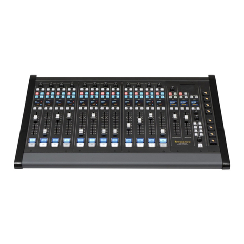
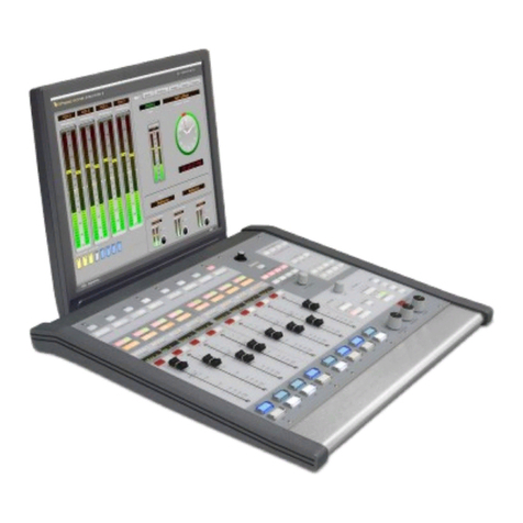
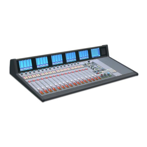
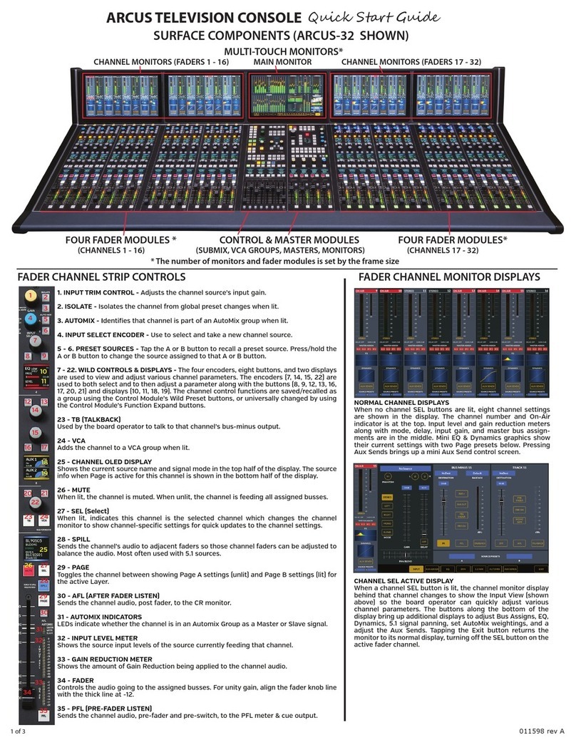
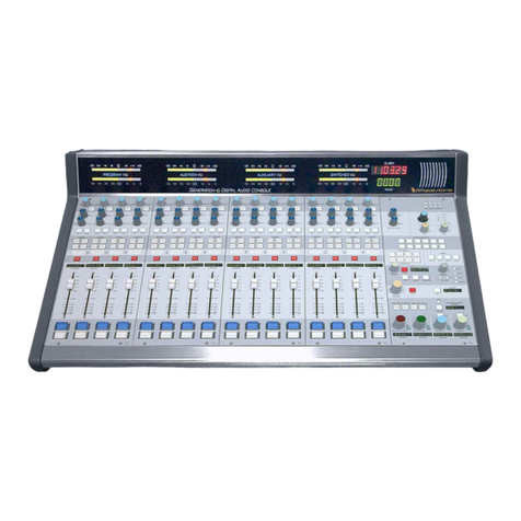
Wheatstone TV-80 User manual

1
TV-80 Router Controller Manual / Nov 98
The Wheatstone
Router Control System
Technical Manual
November 1998
TV-80 Audio Consoles

2
TV-80 Router Controller Manual / Nov 98
600 Industrial Drive, New Bern, NC. 28562
tel 252-638-7000 / fax 252-637-1285
©1998 Wheatstone Corporation
®

3
TV-80 Router Controller Manual / Nov 98
Table of Contents
1.0 SYSTEM OVERVIEW ........................................................................4
2.0 INSTALLATION .................................................................................5
2.1 CONSOLE INSTALLATION.....................................................................5
2.2 EVENT COMPUTER INSTALLATION.....................................................5
2.3 SMART SELECT SWITCH INSTALLATION ...........................................6
2.4 SYSTEM INTERCONNECTION ..............................................................6
2.5 HOUSE SWITCHER ................................................................................7
2.6 AUDIO CONNECTIONS ..........................................................................8
2.6.1 STEREO LINE MODULE......................................................................8
2.6.2 MONO MIC/LINE MODULE..................................................................9
2.7 SYSTEM STARTUP ..............................................................................10
3.0 OPERATION ....................................................................................11
3.1 DEFINITIONS........................................................................................11
3.2 CONSOLE OPERATION ......................................................................14
3.2.1 INPUT CONFIGURATION .......................................................................17
3.3 EVENT COMPUTER OPERATION ......................................................18
3.3.1 INTRODUCTION .....................................................................................18
3.3.2 VIEWING AND EDITING EVENTS .........................................................22
3.3.3 CONFIGURING SOURCE INFORMATION............................................27
3.3.4 MAINTAINING FILES ..............................................................................31
4.0 HARDWARE CONFIGURATION..................................................... 38
4.1 SMART SELECT BUTTON MODULES................................................38
4.2 SMART SELECT BUTTON CONTROLLER.........................................39
4.3 SMART SELECT SWITCH MODULES ................................................39
4.4 SMART SELECT SWITCH CONTROLLER .........................................39
5.0 TROUBLESHOOTING .....................................................................40
5.1 POWER PROBLEMS............................................................................40
5.2 COMMUNICATIONS PROBLEMS .......................................................40
5.3 OTHER PROBLEMS.............................................................................41
ADDENDA - ROUTER DEPENDENT TECH SHEETS
CUSTOMER SUPPLIED COMPUTERS.....................................................42
DI-TECH SWITCHER..................................................................................43
BTS SWITCHER .........................................................................................45
UTAH SWITCHER.......................................................................................48
HORIZON SWITCHER ................................................................................52
SMS7000 SWITCHER .................................................................................55
ARTI INTERFACE .......................................................................................58
TV-80 Router Controller Manual / Dec 01

4
TV-80 Router Controller Manual / Nov 98
ROUTER
CONTROL SYSTEM
PROGRAM
PREVIEW
7PM Nightly News7PM Nightly News
7PM Nightly News
XMAS MassacreXMAS Massacre
XMAS Massacre
STUDIO 7STUDIO 7
STUDIO 7STUDIO 7
STUDIO 7
Event Computer
SCROLL
SOURCE
123
VTR CAM NET
456
789
0
MO
FS REM STU
IN GRP SO
MODIFY
SAVE
NEW
DN UP
DN UP KEY
CH25CH25
CH25CH25
CH25
SCROLL
PREVIEW
PRE TAKE UNDO ARM
CHANNEL SOURCE
ENTERCLEAR
1.0SYSTEMOVERVIEW
The Wheatstone TV-80 Router Control
System provides a degree of automated
control of source selection in the console.
Smart Select buttons on the meterbridge
select1of8differentsourcestoprovidethe
input signal for their associated Input mod-
ule.Theactual switchingof sourceaudiois
doneinarackmountedSmartSelectSwitch
module (available for switching mono mic/
line or stereo line sources). A row of alpha-
numeric displays above the fader panels
quickly shows the operator that the right
source has been selected. The Smart Se-
lect buttons are active only for the primary
source for any given input module. If the
sourceischangedto one of thethreealter-
nate sources, the display will reflect this
change. The source selection on the input
moduleisnotundercomputercontrolinthe
TV-80. The Smart Select button selections
can be saved for recall at a later time.
The System Access Panel, shown
to the left, gives the TV-80 console
operator access to the many
features of the system.

5
TV-80 Router Controller Manual / Nov 98
2.0INSTALLATION
This section describes the installation of the Wheatstone Router Control
System.
2.1 CONSOLE INSTALLATION
The Smart Select Buttons and the System Access Panel use a power supply
separate from that used by the rest of the console. This supply is available in a
failsafe version with two power supplies. Unpack the supply components and
mount the supplies in the equipment rack. Make sure that the power supply
switches are in the OFF position, and connect one end of the power cords to the
power supplies, and the other end of the cords to the AC supply.
TECH NOTE: To insure proper power sequencing in systems using an Event
Computer, we recommend that the PSC-125 Event Computer Power Supply be
connected to the same AC power circuit as the PSC-1000 TV-80 Console Power
Supply. Further, if you have failsafe power supply pairs and have connected each
PSC-1000 to its own separate AC power circuit, as recommended elsewhere in
this manual, we recommend that you connect one PSC-125 to each of those
circuits. If this is not done and the power to the PSC-125(s) is temporarily
interrupted, the console’s Smart Select displays could display inaccurate informa-
tion about the channel sources after the PSC-125(s) restart, requiring the operator
to toggle the source on each of the affected channels to correct the display error.
No other ill effects will be produced.
A power supply cable connects the supply to the rear of the System Access
Panel. (Two cables are provided in the failsafe version.) Connect one end of the
cable to the power supply output connector. The other end of the supply cable can
now be connected to one of the connectors on the rear of the System Access
Panel. If installing the second failsafe supply, connect it in a similar manner, using
the other connector on the rear of the System Access Panel. Note that the Smart
Select Button basket is powered via a cable connecting a DB-15 connector on the
basket to a DB-15 connector on the rear of the System Access Panel.
Further connections to the console components of this system will be made at
a later point in the procedure.
A preliminary check can now be made by turning on the power supplies. The
Smart Select Buttons will briefly light, and then go blank. The source displays will
all show four dots, while the System Access Panel will show the message “Router
CONTROL by WHEATSTONE!” in the preview and program windows. The
channel and source windows will remain blank, and the System Access Panel
LEDs will stay off. The power supply +5 and +12 indicators will light. After verifying
correct operation, turn the power supplies off.
2.2 EVENT COMPUTER INSTALLATION
Unpack the Event Computer and mount it in the equipment rack. Connect one
end of the line cord to the back of the Event Computer and the other end to the AC
power source. If the Event Computer POWER indicator lights, press the POWER
switch to turn it off.
Unpack the computer monitor. If desired, snap the swivel base onto the bottom
of the monitor. Place the monitor on the counter top where it will be used. Verify
that the video cable will reach to the VIDEO port on the back of the Event
Computer. Connect the monitor’s power cord to the AC power source. If the
INSTALLATION
!

6
TV-80 Router Controller Manual / Nov 98
100
Ω
Female
DB-9
Connector
monitor power indicator LED at the lower right front corner of the monitor lights,
press the monitor POWER switch to turn it off. Connect the monitor video cable
to the VIDEO port at the back of the Event Computer.
Unpack the keyboard, plug it in, and place it in a convenient position on the
counter.
Further connections to the Event Computer will be made at a later point in the
procedure.
2.3 SMART SELECT SWITCH INSTALLATION
Unpack the Smart Select Switch rack cage. The unit contains the particular
configuration of mono and stereo switch boards that were ordered, plus a
controller board. One or two (if failsafe option ordered) rack mountable power
supplies are provided. Install the unit in the equipment rack. Unpack the power
supplies and install them in the equipment rack. Connect the power supply cord
to the rear of the supply, and connect the other end of the cord to the AC power
supply. Connect the cables supplied between the power supplies and the cage.
The unit will power up with all LEDs off on the switch modules. The power supply
LEDs will be on.
If your system includes two Smart Select Switch cages, install the second one
in the same manner. If two cages are employed, an FSI-B panel is supplied to
enable the supply to be connected to both cages. In a two cage failsafe
configuration two FSI-B panels are supplied.
When installation is complete, temporarily disconnect the cages from the AC
power supply.
2.4 SYSTEM INTERCONNECTION
To establish a communications link between the Event Computer and the
Smart Select devices, several cables are provided. Cable details are shown here
for your reference. The first cable used is from the Event Computer to the first
peripheral in the chain. The Event Computer end has a female DB-25 connector,
while the peripheral end has a male DB-9 connector. The following chart indicates
the connections:
DB-25 DB-9
2 8
14 3
4 4
5 9
7
6
20
13
19
22
23
INSTALLATION
Male DB-25
Connector

7
TV-80 Router Controller Manual / Nov 98
INSTALLATION
Female
DB-9
Connector
Female
DB-9
Connector
The remaining cables connect each peripheral in the chain to the next one, and
use a male DB-9 connector on each end. The following chart indicates the
connections:
DB-9 DB-9
8 8
3 3
4 4
9 9
Using the cables described, connect from the Event Computer COMM1 port to
one of the I/O ports on the first peripheral, and from the other I/O port of the first
peripheral to one of the I/O ports of the second peripheral, and so on until the last
peripheral is reached. Note that on all devices there is no difference between the
two I/O ports; either port may be used as an input, with the other port used as an
output.
2.5 HOUSE SWITCHER
The details of interconnecting to the house switcher are system dependent. See
the addendum to this manual for further information.

8
TV-80 Router Controller Manual / Nov 98
INSTALLATION
2.6 AUDIO CONNECTIONS
Using shielded, twisted pairs, connect the audio sources and destinations
together as required. The following charts indicate the audio I/O connections for
the Smart Select Switches.
2.6.1 STEREO LINE MODULE
Lower DB-25
Function
13
n/c
25 Channel 5 LT shield
12
Channel 5 LT low
24
Channel 5 LT high
11
Channel 5 RT shield
23
Channel 5 RT low
10
Channel 5 RT high
22
Channel 6 LT shield
9
Channel 6 LT low
21 Channel 6 LT high
8
Channel 6 RT shield
20 Channel 6 RT low
7
Channel 6 RT high
19
Channel 7 LT shield
6
Channel 7 LT low
18
Channel 7 LT high
5
Channel 7 RT shield
17
Channel 7 RT low
4
Channel 7 RT high
16 Channel 8 LT shield
3
Channel 8 LT low
15 Channel 8 LT high
2 Channel 8 RT shield
14 Channel 8 RT low
1
Channel 8 RT high
Upper DB-25
Function
13 n/c
25
Channel 1 LT shield
12
Channel 1 LT low
24
Channel 1 LT high
11
Channel 1 RT shield
23 Channel 1 RT low
10
Channel 1 RT high
22
Channel 2 LT shield
9
Channel 2 LT low
21
Channel 2 LT high
8
Channel 2 RT shield
20 Channel 2 RT low
7
Channel 2 RT high
19
Channel 3 LT shield
6
Channel 3 LT low
18
Channel 3 LT high
5
Channel 3 RT shield
17 Channel 3 RT low
4
Channel 3 RT high
16
Channel 4 LT shield
3
Channel 4 LT low
15
Channel 4 LT high
2
Channel 4 RT shield
14 Channel 4 RT low
1
Channel 4 RT high
Stereo Line Module
Upper DB-25
Female Connector
Stereo Line Module
Lower DB-25
Female Connector

9
TV-80 Router Controller Manual / Nov 98
INSTALLATION
DB-9
Function
5
n/c
9
n/c
4
n/c
8
output, LT shield
3
output, LT low
7
output, LT high
2
output, RT shield
6
output, RT low
1
output, RT high
2.6.2 MONO MIC/LINE MODULE
Stereo Line Module
Female DB-9
Connector
DB-9
Function
5
n/c
9
n/c
4
n/c
8
output, LT shield
3
output, LT low
7
output, LT high
2
output, RT shield
6
output, RT low
1
output, RT high
Mono Mic/Line Module
Female DB-9 Connector
Mono Mic/Line Module
Upper DB-25 Female
Connector
See the TV-80 manual for the audio I/O connections to the console, and see the
appropriate equipment manuals for connection to the house switcher and other
equipment.
Upper DB-25
Function
13
n/c
25
Channel 1 shield
12
Channel 1 low
24
Channel 1 high
11
Channel 2 shield
23
Channel 2 low
10
Channel 2 high
22
Channel 3 shield
9
Channel 3 low
21
Channel 3 high
8
Channel 4 shield
20
Channel 4 low
7
Channel 4 high
19
Channel 5 shield
6
Channel 5 low
18
Channel 5 high
5
Channel 6 shield
17
Channel 6 low
4
Channel 6 high
16
Channel 7 shield
3
Channel 7 low
15
Channel 7 high
2
Channel 8 shield
14
Channel 8 low
1
Channel 8 high

10
TV-80 Router Controller Manual / Nov 98
2.7 SYSTEM STARTUP
The following procedure can be used for an initial check of the system.
Reconnect the Smart Select Switch cages to the AC power source. Turn on the
Smart Select Button / System Access Panel power supplies. The TV-80 console
power supply must also be connected and turned on for this test. Press the
POWER switches on the monitor and the Event Computer. The computer will go
through a series of tasks that will take close to a minute before the program starts.
When the startup process is complete, the following things should have occurred:
(1) the Smart Select Switch LEDs will light to indicate input selection
according to the information defining the first event in the
schedule (see section on event editing);
(2) the Smart Select Buttons will similarly light up according to the
event data;
(3) the Source Displays will indicate the alphanumerics assigned as
defaults for the first event;
(4) the System Access Panel program and preview windows will
display the title of the first event list;
(5) the channel and source windows will remain blank;
(6) the System Access Panel LEDs will remain off;
(7) the house switcher, if connected and in operation, will have
received commands to effect crosspoint selections based on the
event data;
(8) the console surface switches will be set to select the default
power-up source and stereo mode on all inputs, with all other
switches off;
(9) the Event Computer monitor will display the opening screen.
In the event of problems, refer to the troubleshooting section of this manual.
INSTALLATION
NOTE: The default power-up
source 3 (LINE 1) on MIC/
LINE modules and source 1
(LINE 1) on LINE modules.

11
TV-80 Router Controller Manual / Nov 98
3.0 OPERATION
The following section describes in detail the functions and operation of the
Wheatstone Router Control System. Some key definitions are given first, followed
by a description of operation from the console. Last, operation of the Event
Computer is described.
3.1 DEFINITIONS
Within a definition, a term written in UPPER CASE is one which is defined
elsewhere in this section.
DEFAULT- This term refers to the initial data for any EVENT. Each affected
channel is set up for a given source, 1 through 8, to be selected, and the
alphanumerics appropriate to that DEFAULT source are displayed.
DEFAULT (MODULE) INPUT - The module in a given position in the
console can affect the contents of the Source Display. A text file is used to
select which of the inputs of a module is the default input for that module. If the
default input is selected, the Source Display follows the Smart Select Button
selection. If any other input is selected for that module, the display shows the
default text for that input, as stored in the same file. See the section on INPUT
CONFIGURATION.
DUAL FUNCTION KEYS - To facilitate channel and source selection, the
Wheatstone System Access Panel keypad, keys zero through nine, are double
function keys. The first time, in the channel or source selection process, that
one of these keys is pressed, it is interpreted as the alpha prefix, such as “IN”
for channel entry or “VT” for source entry. When the key is pressed again during
selection of the same source, the key represents a digit. The keys are stamped
with both the digit and the channel or source prefix information.
EVENT - This term refers to any of a number of unique system setups. It is
analogous to the terms “program” or “show” in the case of live production.
EVENT COMPUTER- This is the main controller for the Wheatstone Router
Control System. It consists of a PC compatible, hard drive, 3 1/2" floppy drive,
RS-485 serial port, RS-232 serial port, and video. A VGA monitor and a
keyboard are included.
OPERATION

12
TV-80 Router Controller Manual / Nov 98
EVENT LIST- As new events are added, they are stored on this list, which
is sorted according to the EVENT NUMBER.
EVENT NUMBER- A number generated by the system when a new EVENT
is created to identify the event.
HOUSE SWITCHER- This term refers to any routing switcher provided by
a manufacturer other than Wheatstone Corporation, to which the Wheatstone
Router Control System will interface.
LIVE EDIT - This is the process of changing the setup for a single channel
without affecting the rest of the EVENT setup. A channel and source must be
selected. If the channel in question is connected to the HOUSE SWITCHER,
the new source is assigned to Smart Select Button # 8 for that channel. Since
channels not connected to the house switcher have a maximum of eight
sources available to them, it is easier to change one of these channels by simply
pressing the appropriate Smart Select Button for that channel. Any changes
accomplished by this function are not remembered.
MATRIX ID- This term refers to the label by which a source is known to the
HOUSE SWITCHER.
PREVIEW - This function allows the user to check, or PREVIEW, the setup
for the next event in line (the PREVIEW EVENT), without affecting the status
of the current PROGRAM EVENT.
PREVIEW BY KEY - This is the process of selecting the next PREVIEW
EVENT by its EVENT NUMBER.
PREVIEW EVENT - This term refers to the EVENT that is next in line after
the current event. This event in may be selected using the SCROLL PREVIEW
or PREVIEW BY KEY functions. When an EVENT is TAKEN, the system is then
set up for the event that was named in the preview window, that is, the
PREVIEW EVENT.
PREVIEW LOADING - This is the process of sending the data for the
PREVIEW EVENT to the SYSTEM ACCESS PANEL, the SMART SELECT
BUTTONS, and the SMART SELECT SWITCHES by pressing the PRE key.
This is done so that a take can occur as quickly as possible.
PROGRAM EVENT- This term refers to the EVENT that is the current, “on-
air” event. For example, if the program window reads “7PM NIGHTLY NEWS”,
then the system is set up for the news show that occurs at the 7 P.M. time slot,
as programmed by the operator.
SAVE - This function allows allows the user to save changes to the current
PROGRAM event, or to create a new event that is a copy of the current
PROGRAM event.
SCROLL PREVIEW- This is the process of selecting an EVENT to become
the new PREVIEW EVENT. The up key selects items later in the EVENT LIST
(events having a higher EVENT NUMBER), while the down key selects items
earlier in the EVENT LIST (events having a lower event number).
OPERATION

13
TV-80 Router Controller Manual / Nov 98
SCROLL SOURCE - This is one method of selecting a new source for
assignment to a channel when doing a LIVE EDIT. The up key selects items
later in the SOURCE LIST, while the down key selects items earlier in the source
list.
SMART SELECT BUTTON- The modules, located in the TV-1000 console,
that enable the console operator to select a new source for an input channel.
The sources are predefined for each EVENT, and may represent sources
available from the SMART SELECT SWITCHES or from the HOUSE
SWITCHER, depending on which type of source is connected to the module’s
corresponding console channel. Each module has eight buttons, allowing
selection of one of eight sources for each module. If the module represents an
output from the house switcher, any inputs available to the switcher for that
switcher output may be preassigned to one of the Smart Select Buttons.
Additionally, button 8 of a house switcher channel can be assigned “on the fly”
by using the LIVE EDIT function. Communications from the EVENT COM-
PUTER to the Smart Select Button is established through a Smart Select Button
Controller module.
SMART SELECT SWITCH- This is one of up to eighteen modules contained
in a separate rack mount cage. There are two module types available: the
stereo line module and the mono mic/line module. Each module is a 1 of 8
source selector, with LEDs to indicate the source selected. Communications
from the EVENT COMPUTER to the Smart Select Switch is established through
a Smart Select Switch Controller module, located to the right of the last Smart
Select Switch module in the cage. A system may employ one or two Smart
Select Switch cages.
SOURCE DISPLAYS - These are four digit, 5X7 dot matrix, alphanumeric
displays, located in a row above the fader modules. The exact number of
displays is dependent on console size, number of modules, and desired number
of display positions, but generally would include one display at each input
position, and possibly a few at auxiliary positions. The information displayed is
the name of the current source, in the case of input channels, but is not limited
to this use. The display contents are defined in the EVENT definitions. The
system is capable of having different display contents for each Smart Select
Button associated with that channel. In the case of console positions that do not
have Smart Select Buttons, only one display word is made available per event.
The contents of group and output displays may be changed from the System
Access Panel.
SOURCE LIST - This is a list, in alphanumeric order, containing all of the
source names available for display in the SOURCE DISPLAYS. Included are
sources specifically related to the HOUSE SWITCHER, as well as general
sources available for all other channels. The list also includes MATRIX ID
information. This list can be edited by the user; see the section on CONFIGUR-
ING SOURCE INFORMATION.
OPERATION

14
TV-80 Router Controller Manual / Nov 98
SYSTEM ACCESS PANEL - This is a module in the TV-1000 console that
enables the console operator to call up a predefined group of source assign-
ments, also known as an EVENT, and to perform limited editing of the event
data. The module contains display WINDOWS to show the names of the
current PROGRAM and PREVIEW events, as well as channel and source
information used during a LIVE EDIT. The module also has four LED indicators
to show the status of various module functions, and a total of twenty four keypad
switches for function selection and data entry.
TAKE - This is the process of changing the system setup from the one
defined by the current PROGRAM EVENT to the one defined by the next event
in line, the PREVIEW EVENT. The preview event then becomes the new
PROGRAM EVENT.
UNDO - This function is the opposite of TAKE, and allows a chance to
recover from a premature or erroneous EVENT take. For example, assume
event A is the PROGRAM EVENT and event B is the PREVIEW EVENT. A take
makes event B the program event. An UNDO would then make event A the
program event and event B the preview event once again. There is only one
level of UNDO. If UNDO has been done and a subsequent take has not been
done, the UNDO function will do nothing.
WINDOWS- The System Access Panel has four display windows, one each
for channel, source, preview, and program. The program window shows the
title of the EVENT for which the system is currently configured, and the preview
window shows either the title of the current PROGRAM event, or the title of an
event that has been selected for PREVIEW. When performing a LIVE EDIT,
the channel window shows the name of the channel for which the source is to
be altered, and the source window shows the name, and MATRIX ID, if
applicable, of the new source being selected.
3.2 CONSOLE OPERATION
INITIAL CONDITIONS - In order to describe the operation of the system, we
must start with a known condition. The assumption, unless otherwise noted, is
that the last operation performed was a TAKE. Therefore, the program window
contains the name of the program event, the preview window also contains the
name of the program event, the Source Displays contain the default alphanumerics
for the program event, the Smart Select Buttons are lit according to the default data
for the program event, the Smart Select Switches are set according to the default
data for the program event, and the house switcher has received the default data
for the program event. The channel and source windows are blank, and the
System Access Panel LEDs are off.
PREVIEWING AN EVENT - After first selecting an event for preview by
scrolling or by key (see below), pressing the PRE key on the System Access
Panel initiates a PREVIEW. The Source Displays will show the source names for
OPERATION
NOTE:
In the sections that
follow, reference to control
buttons and keys on the
Router Control Panel and the
Event Computer keyboard
will always be printed in out-
line type. That is, if a button
or key under discussion has
the legend “ENTER” printed
on it, it will be referred to in
the text as ENTER.

15
TV-80 Router Controller Manual / Nov 98
OPERATION
the preview event. These displays will be flashing, as will the preview window
display, to indicate that the system is in the preview mode. This allows the operator
to check the source names of the preview event without taking the event. Pressing
PRE again will exit from the preview mode. It is not necessary to exit from the
preview mode before performing another function; this will be done automatically.
TAKING AN EVENT - To prevent accidental takes, the ARM key must be
pressed to arm the take function. Press ARM and the ARM LED will flash,
indicating that the panel is ready to act on a take (or an undo). Then press TAKE
when you are ready, and the take process will occur, updating the Source
Displays, the preview and program windows, the Smart Select Switches and
Buttons, and the house switcher, and turning off the ARM LED. If TAKE is not
pressed, the ARM LED will go out after about ten seconds, indicating that the
system is no longer ready to perform a take or undo.
UNDOING AN EVENT- Should the operator take an event prematurely, or take
the wrong event, press ARM and UNDO. This will return the system to its status
prior to the last take, with the last program event being once again the current
program event, and the last preview event (the one just taken) becoming the
preview event once again. As in the take process, the ARM LED begins flashing
when ARM is pressed, and goes off when UNDO is pressed, or when the arm
timeout occurs.
PREVIEW SCROLL - There are two ways of selecting an event for preview.
One way is to use the preview scroll keys. The key ("UP") will select the next
event in the event list, and display its name in the preview window. The key may
be pressed repeatedly to advance through the event list to the desired event, or
the key may be held down, allowing the program to scroll through the list on its own.
The key ("DOWN") works in a similar manner. Please note that changing the
previewed event means that any preview data loaded to the Source Displays by
pressing the PRE key is no longer valid. Once the desired preview event is
selected, press the PRE button. After a slight delay, while the new preview data
is loaded, the preview mode is entered, and the new data is now ready for use. If
this is not done, the new data will still be loaded when the ARM key is pressed prior
to the next take. If PRE is not pressed, and TAKE is pressed immediately after
ARM, the take will be delayed while the data is being loaded.
PREVIEW BY KEY- The second way of selecting a preview event other than
the next one in line is to use the KEY key. To use this feature, you must know the
unique event number for the event in question. To learn how to determine the
event number you need, please see the section describing the Event Computer
operation. As an example, suppose you have an event called “FUND RAISER”
that has an event number of 142. To call this event up for preview, press KEY.
The KEY LED will flash. The preview window display changes to prompt you for
the three digit event number. Use the numeric keypad above the left side of the
preview window to enter the digits 1, 4, and 2. If the number required is less than
100, you only need enter two digits, or one digit for numbers below ten. After

16
TV-80 Router Controller Manual / Nov 98
entering the required digits, pressENTER on the keypad. The preview window
will now show the title of the desired event, and the KEY LED will stop flashing.
As noted in the above section (PREVIEW SCROLL), you should use PRE to make
sure the data for the new preview event is loaded to avoid delays at take time.
SMART SELECT BUTTONS- The Smart Select Buttons are provided as a way
of quickly selecting a new source for a given channel without changing the source
assigned to any other channel. When an event is set up with the Event Computer,
the primary source for each channel is set up as the default source. This means
that when an event is taken, the Smart Select source selected as the default
source is the one that will be connected, via the Smart Select Switches or the
house switcher, to the input of that channel. The alphanumerics for that same
source will be displayed in the Source Display above the fader, if the corresponding
module's default input has been selected, and the corresponding Smart Select
Button indicator will light. When the operator wants to select one of the other
seven available sources, it is only necessary to push the appropriate button. The
Smart Select Switch or house switcher will update, the new button indicator will
light, and the Source Display will update, depending on the input selected on the
corresponding module.
LIVE EDIT- For channels connected to the house switcher, the live edit function
provides a way of selecting a source other than the ones defined for Smart Select
Buttons 1 through 8 for that channel in the event data.
CHANNEL SELECT - Assume that a new source is to be assigned to
channel 36 of the console. Press the dual function key IN/7. The channel
display shows “IN”. Press the 3key, and the display changes to “IN3”. Press
the 6key and the display changes to “IN36”. Press ENTER and the display
flashes, indicating a valid channel entry. If an error is made prior to pressing
ENTER, pressCLEAR and start over. IfENTER is pressed and then the error
is discovered, press CLEAR three times, then start over.
SOURCE SELECT- Assume that VT51 is the source to be assigned to the
channel. Press the dual function key VTR/1. The Source Display will show
“VT”. Press the 5key and see “VT5”. Press the 1key and see “SnnnVT51”,
where “nnn” is a three digit matrix id code for the house switcher. Press ENTER
and the display flashes, indicating selection of a valid source. CLEAR can be
used, as above, to allow reentry after errors. If the source is one that is not in
a group whose prefixes are found on the dual function source keys (1through
6), then the SCROLL SOURCE keys must be used to scroll through the source
list to find the appropriate source name. Even if the source is one that can be
selected using the dual function keys, the scroll function can optionally be used
to select that source.
TAKE THE SELECTION - Once a valid channel and source have been
selected, press theSAVE key. The channel and source windows stop flashing.
The source selected has now been assigned to Smart Select Button 8 for that
channel. When the operator is ready, Smart Select Button 8 is pressed to
OPERATION

17
TV-80 Router Controller Manual / Nov 98
complete the source assignment. The house switcher will update, as will the
Source Display. If the house switcher uses substitute names for sources, the
Source Display will show the name tallied by the house switcher.
The live edit feature can also be used to change the alphanumerics of the
Source Displays at the group and output positions. Use the appropriate dual
function key to start the channel selection process, and use the SCROLL
SOURCE keys to find the desired alphanumeric.
SAVING CHANGES TO AN EVENT- The key sequenceMODIFY, SAVE, will
save the current status of the console, including Smart Select Buttons, to the
current program event. Any changes made using the live edit feature will not be
saved.
CREATING A NEW EVENT - The key sequence NEW , SAVE , will save the
current status of the console to a new event. A temporary name is assigned to the
new event, and displayed in the program window. The temporary name will be of
the format "Event Number nnn" where nnn is the next available event number. The
name may be changed from the computer keyboard. Instructions to do this are
found in the section VIEWING AND EDITING EVENTS under the subtitle
CHANGING THE EVENT TITLE.
3.2.1 INPUT CONFIGURATION
A configuration file, TV80CHAN.CFG, is used to indicate which input for a given
module on the console is wired to the Smart Select System, or to the House
Switcher. This input is considered the default for that module, and the corresponding
Source Display contents will follow the Smart Select Button for that channel. If a
different input is selected, the Source Display will display alternate information as
stored in the file.
The following paragraphs describe the file format and give instructions on how
to alter the factory configuration.
Here are some typical lines from the file:
Ø
1>
ØØ
>X>
Ø
>
Ø
5>
Ø
1>
I
>1>INP1>INP2>INP3>INP4>
Ø
6>
Ø
2>
I
>2>INP1>INP2>INP3>INP4>
16>12>M>1>EXT1>EXT2>EXT3>EXT4>AUX1>AUX2>AUX3>AUX4>AUX5>AUX6>
AUX7>AUX8>MST1>MST2>SUB1>SUB2>SUB3>SUB4>SUB5>SUB6>
SUB7>SUB8
The first line is for a channel that does not have a display. The "
Ø
1" indicates
that the information is for the module at position 1 in the console. The "
ØØ
"
indicates that the channel is not mapped to a Smart Select System channel. The
"X" indicates that the position doesn't have a display. The "
Ø
" indicates that there
are no default inputs, or none that need to be considered. This description can
apply to any module that has no external inputs or to any position that has no
display. The ">" characters are used to delineate the line into fields for easier
reading on the screen or on paper.
OPERATION

18
TV-80 Router Controller Manual / Nov 98
On the second line, the "
Ø
5" indicates that the information is for the module at
position 5 in the console. The "
Ø
1" indicates that the channel is mapped to Smart
Select channel 1, corresponding to the input IN
Ø
1 in event listings displayed when
using the program's event editing feature. The "
I
" indicates that the module is an
input module. The "1" indicates that input 1 of this module is wired to follow the
Smart Select Buttons. If the module has input 2 selected, the Source Display will
indicate "INP2", if input 3 is selected the display will be "INP3", and if input 4 is
selected the display will be "INP4". If the desired text is less than 4 characters,
it must be padded with spaces to be exactly 4 characters in length.
Line 3 is only slightly different in effect than line 2. If input 1 is selected, the
display will be "INP1", while if input 2 is selected, the display will follow the Smart
Select Buttons. Note that this line applies to the module in console position 6 and
is mapped to Smart Select channel 2 (IN
Ø
2).
The fourth line shows how to handle a monitor module in position 16 if the
position also has a display. Since the monitor module has 24 inputs, this line is
longer than the previous lines, to show the alternate display text for all 24 inputs.
Note that only 1 character is used to indicate the default input. Use "A" for input
10, "B" for input 11, etc.
To edit the file, any text editor may be used, as long as it has a text-only mode
so that no text formatting information is added to the file. The editing should be
done while the Event Computer is not running its program. Best results are
obtained by having the text editor in overwrite mode. The factory-provided file will
have the file lines in numeric order according to console position. Do not change
this order. To change the default input number, position the text editor's cursor
at the appropriate location and type the desired designation. Use a zero for a
channel that has a display but no Smart Select Buttons. If using a letter to indicate
an input higher than 9, use upper case letters only. Do not use an input designation
higher than the number of inputs available on the module. When typing new
display text, always use exactly four characters. Any printable characters may be
used, including the ">" character.
Before editing this file, save a copy. If you experience any problems with the
edited file, at least you have a usable file as backup.
3.3 EVENT COMPUTER OPERATION
3.3.1 INTRODUCTION
The Event Computer serves as the master controller for the Wheatstone Router
Control System, as well as the user interface for creating, editing, scheduling, and
maintaining event data. This section contains a detailed explanation of the Event
Computer functions and operation.
INSTALLATION - The Event Computer is shipped with the required
software installed, and the user will not normally need to deal with this subject.
There are, however, two exceptions. First, any future software updates will
require installation; details, of course, would be provided at that time. Second,
in the event of catastrophic failure, such as hard disk failure, the software must
be reinstalled after the hardware repairs have been made. The system is
shipped with the disks and documentation for the operating system. This must
be installed first, following the instructions provided. Since the Wheatstone
OPERATION

19
TV-80 Router Controller Manual / Nov 98
install program will overwrite the operating system AUTOEXEC.BAT and
CONFIG.SYS files, choose the operating system install options that leave the
choices up to the install program. When the operating system installation is
complete, put the ECOM80 install disk in the floppy drive and type A:INSTALL
to begin. The procedure is automatic, and requires no user input to run to
completion. Consult the factory if any install problems occur.
BACK UP YOUR FILES- Since the ECOM80 install program overwrites all
event, source, and utility configuration files, make sure you back up your data
periodically. See details in the section on MAINTAINING FILES.
THE ECOM80 PROGRAM - The ECOM80 program is a multitasking
program, having the ability to perform more than one operation at a time. This
allows one operator to perform routine event editing and scheduling while a
second operator can be working the console. Certain restrictions to multitask-
ing apply during file maintenance. See the section on MAINTAINING FILES for
details.
TASK PRIORITY- The priority task handled by the program is the operation
of the console System Access Panel, Smart Select Buttons and Switches,
module input switches, and transmission of commands to the house switcher.
The System Access Panel keys, the Smart Select Buttons, and the module input
switches are constantly interrogated, allowing operator input to be acted upon
quickly. During the idle times between these interrogations and actions, the
Event Computer keyboard is interrogated, and this operator input is then also
acted upon.
SPECIAL KEYS - The program makes use of several control keys for its
operation. These will be designated as, for example, Ctrl-V, orCtrl-Enter, in
the instructions. The first example is entered by holding down either Ctrl key
(there are two of them on the keyboard) while pressing the Vkey. In the second
example, press Enter instead of theVkey. The program makes use of other
special keys, too. TheEsc key is used to cancel an operation; use this if you
have started to do something, but have decided for some reason not to finish
it. Among function keys F1 throughF12, F1 is used in the program. The Tab
key is used, as are the comma, Insert, Delete, Home, End, Page Up, and
Page Down keys, the four arrow keys, for up, down, left, and right movement,
and the Backspace key. The function of this last key is NOT the same as the
left arrow key previously mentioned, so take care not to confuse the two. The
numeric keypad, at the right side of the keyboard, has keys whose function
depends on the status of theNum Lock key; these keys should not be used
unless you become familiar with the way they work relative to the Num Lock
function. In any event, their use is not required.
OPERATION

20
TV-80 Router Controller Manual / Nov 98
OPERATION
HELP SCREENS -
Theprogram providesa generalpurpose helpscreen, availableat anytime
bypressingtheF1F1key. Iftheuseriscurrentlyinthefilemaintenancefunctions,
F1F1providesasecondhelpscreenthatdealsspecificallywithfilemaintenance.
General Help Screen
File Maintenance
Help Screen
Other manuals for TV-80
1
Table of contents
Other Wheatstone Recording Equipment manuals

Wheatstone
Wheatstone G-5 User manual

Wheatstone
Wheatstone TV 1000 User manual

Wheatstone
Wheatstone D-8000 User manual

Wheatstone
Wheatstone E-Series Guide

Wheatstone
Wheatstone ARCUS User manual

Wheatstone
Wheatstone E-5 User manual

Wheatstone
Wheatstone A-6000 User manual

Wheatstone
Wheatstone D-5000 User manual

Wheatstone
Wheatstone SP-8 User manual

Wheatstone
Wheatstone M-2 User manual