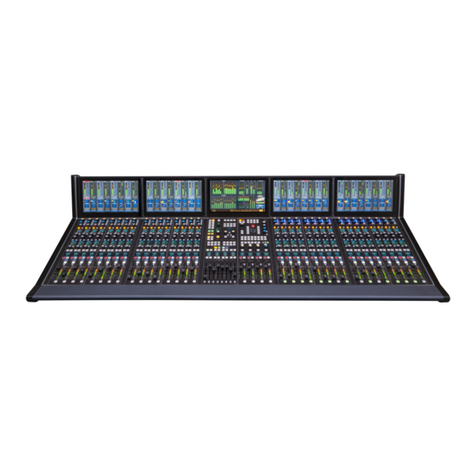
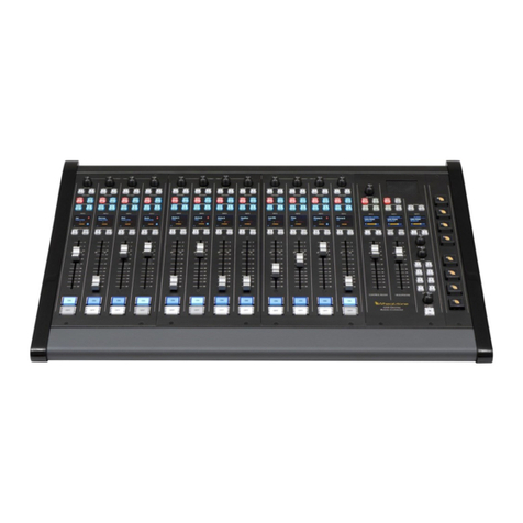
Wheatstone SP-8 User manual

T
TE
EC
CH
HN
NI
IC
CA
AL
L
M
MA
AN
NU
UA
AL
L
SP-8Audio Console
600 Industrial Drive, New Bern, N.C. 28562 (tel 252-638-7000 / fax 252-637-1285 / email@wheatstone.com)
®

SP-8 / Mar 99
SP-8 Series Audio Consoles Technical Manual (revised)
©1999 Wheatstone
®
Corporation
600 Industrial Drive
New Bern, North Carolina 28562
252-638-7000 (Fax 252-637-1285)

IMPORTANT
In order to pass audio through your new console,
you must wire up insertion points in certain modules.
See the DB-25 pinout section in your manual for details:
SP-8
Note in particular
MG-08 group module,
SM-08, MM-08 output modules.
MG-08 (see page 3-4): connect CH1 insert out HI to CH1 insert in HI, CH1 insert out LO to
CH1 insert in LO, CH2 insert out HI to CH2 insert in HI, CH2 insert out LO to CH2 insert in
LO,SEND insert out HI to SEND insert in HI and SEND insert out LO to SEND insert in LO.
SM-08 (see page 3-8): connect LT insert out HI to LT insert in HI, LT insert out LO to LT insert
in LO, RT insert out HI to RT insert in HI and RT insert out LO to RT insert in LO.
MM-08 (see page 3-12): connect SUM insert out HI to SUM insert in HI, SUM insert out LO to
SUM insert in LO, MONO insert out HI to MONO insert in HI and MONO insert out LO to
MONO insert in LO.

SP-8 / August 2000
Addenda
IMPORTANT:
The SP-8 audio console is a modular design, intended for
custom configuration per specific client requirements. Thus, the technical
drawings in this manual, which document all available options, may show
features and circuitry that do not appear on your specific console.
Please note the following additions and corrections to this
technical manual.
CS-08 CONTROL ROOM/MONITOR MODULE:
Resistiors R56, R57 and R61, R62 (24Ω) have been changed to polyswitches R56 and R61 (.17A).
Resistor R101 is now 40.2K.
METERBRIDGE PRESELECTOR (MBLS):
R17, R18 have been changed from 1kΩto 750Ω.

Contents - Page 1
SP-8 / Dec 95
Table of Contents
SP-8 / Apr 99
INSTALLATION
Mounting the Console to the Leg Stand ....................................................1-1
Console Power Supply ...............................................................................1-2
Dual Failsafe Supply .............................................................................1-2
Power Supply Schematic ......................................................................1-3
Power Supply PCB Drawing.................................................................1-4
Power Supply Relay Card Schematic ...................................................1-5
Power Supply Relay Card Load Sheet Drawing................................... 1-6
System Ground...........................................................................................1-7
Typical Grounding Scheme (dwg)........................................................1-7
Further Grounding Details ....................................................................1-8
INPUT MODULES
Mono mic/line input ........................................................................ 2-2
Signal Flow Diagram .................................................................. 2-2
Front Panel Controls ................................................................... 2-3
Logic Functions........................................................................... 2-4
DipswitchProgrammable Features ............................................. 2-4
I/O Connections .......................................................................... 2-5
Printed Circuit Card Dwg ........................................................... 2-6
Schematic .................................................................................... 2-7
Bus Assign Switch Card PCB Dwg .......................................... 2-12
Bus Assign Switch Card Schematic.......................................... 2-13
Cue Switch Card PCB Dwg ...................................................... 2-14
Cue Switch Card Schematic...................................................... 2-15
Dual Mono mic input..................................................................... 2-16
Signal Flow Diagram ................................................................ 2-16
Front Panel Controls ................................................................. 2-17
Logic Functions......................................................................... 2-18
DipswitchProgrammable Features ........................................... 2-18
I/O Connections ........................................................................ 2-19
Printed Circuit Card Dwg ......................................................... 2-20
Phantom Power Switch Card PCB Dwg ................................... 2-21
Phantom Power Switch Card Schematic..................................2-21a
Schematic .................................................................................. 2-22
Bus Assign Switch Card PCB Dwg .......................................... 2-27
Bus Assign Switch Card Schematic.......................................... 2-28
Cue Switch Card PCB Dwg ...................................................... 2-29
Cue Switch Card Schematic...................................................... 2-30

Contents - Page 2
SP-8 / Dec 95
T
ABLE
OF
C
ONTENTS
SP-8 / Dec 96
Dual mono line input ..................................................................... 2-31
Signal Flow Diagram ................................................................ 2-31
Front Panel Controls ................................................................. 2-32
Logic Functions......................................................................... 2-33
DipswitchProgrammable Features ........................................... 2-33
I/O Connections ........................................................................ 2-34
Printed Circuit Card Dwg ......................................................... 2-35
Schematic .................................................................................. 2-36
Mode Switch Card PCB Dwg ................................................... 2-41
Mode Switch Card Schematic................................................... 2-42
Cue Switch Card PCB Dwg ...................................................... 2-43
Cue Switch Card Schematic...................................................... 2-44
Stereo line input............................................................................. 2-45
Signal Flow Diagram ................................................................ 2-45
Front Panel Controls ................................................................. 2-46
Logic Functions......................................................................... 2-47
DipswitchProgrammable Features ........................................... 2-47
I/O Connections ........................................................................ 2-48
Printed Circuit Card Dwg ......................................................... 2-49
Schematic .................................................................................. 2-50
Mode Switch Card PCB Dwg ................................................... 2-55
Mode Switch Card Schematic................................................... 2-56
Cue Switch Card PCB Dwg ...................................................... 2-57
Cue Switch Card Schematic...................................................... 2-58
GROUPSAND OUTPUT MODULES
GroupSubmasters ........................................................................... 3-2
Signal Flow Diagram .................................................................. 3-2
Front Panel Controls ................................................................... 3-3
I/O Connections .......................................................................... 3-4
Printed Circuit Card Dwg ........................................................... 3-5
Master Stereo Output....................................................................... 3-6
Signal Flow Diagram .................................................................. 3-6
Front Panel Controls ................................................................... 3-7
I/O Connections .......................................................................... 3-8
Printed Circuit Card Dwg ........................................................... 3-9
Mono Master Output ..................................................................... 3-10
Signal Flow Diagram ................................................................ 3-10
Front Panel Controls ................................................................. 3-11
I/O Connections ........................................................................ 3-12
Printed Circuit Card Dwg ......................................................... 3-13
Group/OutputModules
Schematic .................................................................................. 3-14
DC Offset Card Schematic........................................................ 3-19

Contents - Page 3
SP-8 / Dec 95
MONITOR AND OPTIONAL MODULES
Control Room/Studio Monitor ....................................................... 4-2
Signal Flow Diagram .................................................................. 4-2
Front Panel Controls ................................................................... 4-3
I/O Connections .......................................................................... 4-4
Printed Circuit Card .................................................................... 4-6
Schematic .................................................................................... 4-7
Optional Second Studio ................................................................... 4-9
Signal Flow Diagram .................................................................. 4-9
I/O Connection .......................................................................... 4-10
Schematic .................................................................................. 4-11
Optional Line Selector................................................................... 4-12
I/O Connections ........................................................................ 4-13
Schematic .................................................................................. 4-14
Optional Tape Remote................................................................... 4-15
I/O Connections ........................................................................ 4-16
Schematic .................................................................................. 4-17
Clock Printed Circuit Card ............................................................ 4-18
Clock Control Printed Cicuit Card ................................................ 4-19
Clock/Clock Control Schematic................................................ 4-20
Timer Printed Circuit Card............................................................ 4-21
Timer Control Printed Circuit Card............................................... 4-22
Timer/Timer Control Schematic ............................................... 4-23
Optional Meterbridge Pre-Select ................................................... 4-24
I/O Connections ........................................................................ 4-25
Printed Circuit Card .................................................................. 4-26
Schematic .................................................................................. 4-27
APPENDIX
BALANCED vs UNBALANCED I/O CONNECTIONS ........................A-1
Typical Unbalanced Connections (dwg) ............................................A-2
NOTES ON LEVEL MEASUREMENT.................................................. A-3
TROUBLESHOOTING............................................................................ A-3
Basic Procedures ................................................................................ A-3
Testing a "Live" Console – Precautions............................................. A-3
Integrated Circuits .............................................................................. A-4
OTHER DETAILS.................................................................................... A-5
FURNITURE LEG SET ASSEMBLY INSTRUCTIONS....................... A-6
SP-8 / Dec 96SP-8 / Mar 99

Page 1 - 1
SP-8 / Dec 95
Installation
Mounting the Console to the Leg Stand
This SP-8 series console comes supplied with a factory leg support. The
console leg furniture consists of four pieces:
two end panels – the curved edge goes towards the front (armrest) of the
console.
frontspanningpanel–thismountsbetweenthetwosidepanels,justahead
of the vertical center aluminum brackets. The narrow finished wooden strip
(cherry) is the bottom; the wider unfinished (pine) strip is the top.
rearspanning panel– mounts between the two side panels, along the rear
edge. The rear panel differs from the front panel in that it has been pre-drilled
with four 1/4" holes that accept enamel-finished #10 machine screws that go
into four tapped holes on the side panels' rear vertical brackets. Note when
correctlymountedintoplacethereisa5/8"gapbetweenthebottomoftherear
panelandthefloortoallowconsolewiringtoexitthelegassembly.Onceagain,
the finished wood strip is the bottom; the wider pin strip is the top.
The SP-8 leg stand has been pre-assembled at the factory and then broken
downforshipment.Allassemblyholes havebeenpre-drilled. Tore-assemble
the leg stand:
(1) attach the two side panels to the front spanning panel, using the eight
screws provided. The bottom of the panel should flush with the floor and the
bottom edge of the side panels. The side panel curves should face front.
(2) Attach the rear spanning panel to the side panels' rear vertical brackets,
usingthefinished#10screwsprovided. Note the finished wooden edgeofthe
panel (cherry) should be along the lower edge approximately 5/8" from the
floor. (This step "squares up" the leg assembly and readies it for the console.)
(3)RemovetheSP-8console'srearconcealmentpanelandplacetheconsole
onthelegstand,withthearmrestfacingforward.Notetheconsolewoodenend
pieces just straddle the leg stand side pieces. Roughly align the console front
to back so the rear edge of the console side pieces are roughly even with the
back edge of the leg stand side pieces.
(4)Removethelegstandrearspanningpaneltogainaccesstotheunderside
of the console.
(5) Note the wooden bottom of the console has been pre-drilled to accept
screws coming up through the top of the front spanning panel and to accept
screwsfromtworearside brackets already pre-attached tothelegsidepieces.
Ifnecessary, makeafinalfront-to-backadjustmentoftheconsolesotheholes
onthebracketsandspanningpanelpinestriplineupwiththepre-drilledholes
in the bottom of the console.
CHAPTER CONTENTS
Mounting the Console to the Leg Stand .......................................... 1-1
Console Power Supply .................................................................... 1-2
Dual Failsafe Supply................................................................... 1-2
Power Supply Schematic ............................................................ 1-3
Power Supply PCB Drawing....................................................... 1-4
Power Supply Relay Card Schematic ......................................... 1-5
Power Supply Relay Card Load Sheet Drawing......................... 1-6
System Ground ................................................................................ 1-7
Typical Grounding Scheme (dwg).............................................. 1-7
Further Grounding Details .......................................................... 1-8
SP-8 / Apr 99

Page 1 - 2
SP-8 / Dec 95
I
NSTALLATION
SP-8 / Apr 99
(6) Attach the console to the leg stand using the screws provided.
(7) Re-attach the rear spanning panel.
(8) Re-attach the console rear concealment panel.
THE CONSOLE POWER SUPPLY
The console power supply is a standard 19" rackmount unit. It should be
mountedinanadjacentequipmentrackwithin15feet(butpreferablynocloser
than 3 feet) of the console. The mounting location should allow proper air
circulation around the unit. Avoid locating any high gain equipment (such as
phono preamps, tape recorders, etc.) too near the power supply, to avoid
magnetic interference into that equipment.
The power supply is fitted with a 3-wire grounded AC cord that should be
plugged into a clean 120V AC outlet (that is, an AC source that feeds only the
controlroomaudiogear). ThisACsourceshouldbeaseparatefeedfromthose
powering lighting, air-conditioning, or any other non-audio machinery. The
third pin ground wire of the AC source should be tied to the central system
ground point (see SYSTEM GROUND below).
Withthepowersupplyinplace, plugintheACpowercord. Notethe power
supplyusesa3-ampslo-blofuse(backofchassis). ThefiveLEDindicatorson
thesupply'sfrontpanelshouldlightup(PHANTOM,+V,–V,+5V,and+24V).
Unplug the power supply and connect it to the console, using the supplied
multi-conductorcable. Notethecableplugsintothebackofthesupplychassis
andintothebottomoftheconsole(righthandend). Withtheconsoleconnected,
re-energize the power supply. The display indicators should again light; the
console'sVUmetersshouldlightup,andindividualmoduleON/OFFswitches
and green CUE LEDs will power up randomly.
Dual Failsafe Supply
Yourconsolemayhavebeenorderedwithadualfailsafeoption;inthiscase
youwillhavetwoseparaterackmountsupplies. Ifthisisthecase,thenconnect
both supplies to the console with the two cables supplied. Note that both
supplies must be energized for the failsafe function to work.
The first major installation step is to make sure the console is properly
grounded. Unplug the power supply, and proceed with the next section,
"SystemGround".
The power feed recommended
in the text is often installed and
referred to in studios as an
"isolated AC ground" outlet.
It is usually orange in color.

Page 1 - 3
SP-8/Aug 2001


12
56
7
8
910
K1
CT1
2
3
1
WP5
0.0047uF
C3
22K
R1
0.0047uF
C4
CGND
HEAVY
DUTY A.C.
SUPPLY
CABLE
105-120
VAC
50-60Hz
INPUT
WP1
WP4
WP6
22K
R2
22K
R3
22K
R4
BLACK
BLACK
6A4
D1
6A4
D2
200V
47uF
C2
3.3
R8
3.3
R9
3.3
R7
WP2 WP3
CGND
47uF
200V
C1
22K
R5
22K
R6
600 Industrial Drive
New Bern, NC 28562
Page 131-A
Power Supply Relay Card Schematic - Sheet 1 of 1
_
SA
1 OF 1
PSR-1000
W# 700340 PSR-1000B PCB
45S0108B
TV-1000/Dec 1999
12-2-99
REVSIZE
SCALE
FSCM NO. DWG. NO.
SHEET
CONTRACT NO.
APPROVALS DATE
DRAWN
CHECKED
ISSUED B
1
B
2
2 1
A A
B
15A
NOTES:
FAILURE MODES:
1.RELAY COIL AND/OR DRIVE CIRCUIT
FAILS- NO "SOFT START".
2.RELAY CONTACTS FAIL- ALLWAYS
"SOFT START", DC OUTPUTS APPROACH
DROPOUT.
3.PLUGING PWR CORD WITH PWR SWITCH ON-
NO "SOFT START".
NOTES:
ALL "SOFT START" COMPONENTS
PCB MOUNTED AND ATTACHED TO
110V AC SOCKET, NO HAND WIRING
OR METAL CHANGE IS REQUIRED.


Page 1 - 5
SP-8 / Dec 95
I
NSTALLATION
SYSTEM GROUND
Safety requirements dictate that a positive connection from the console
mainframe to electrical ground be made in the completed installation.
The system ground serves two important purposes:
(1) Provides a zero signal reference point for the entire audio system;
(2) Assure safety from electrical shock.
There exist two terms that one encounters in a discussion of ground:
(A)EARTHGROUND,whichisusuallyaheavycopperroddriveninto
thesoiladjacenttothebuilding(around6feetdown)oraconnection
to the copper water pipes leading into the building. Either is
acceptable, unless, of course, the water pipe is plastic.
(B)THEPOWERCOMPANYEARTHCONDUCTORthatentersthe
building at the power line breaker box; this conductor should be
(and is often by code) tied to the above-mentioned earth ground at
one point. This point is the SYSTEM EARTH GROUND.
CONSOLE
2-TRACK
MULTI-TRACK
AC BREAKER
BOX
DEVICE 1
DEVICE 2
DEVICE N
CONSOLE POWER SUPPLY
CONTROL ROOM POWER AMP
STUDIO POWER AMP
OTHER
POWER COMPANY
EARTH GROUND
HEAVY
(#4 or #6)
COPPER
WIRE
HIGH POWER
EQUIPMENT RACK
COPPER ROD
SOIL
3-wire ground or separate wire run from chassis
EFFECTS RACK
MIC PANEL
GND
TYPICAL SYSTEM
GROUNDING SCHEME
etc.
3–5 ft.
The grounding point on SP-8 consoles is a terminal lug strip located on the
bottom of the mainframe, near the power connector. This is the central
grounding point for the console mainframe. TIE THE CONSOLE
MAINFRAME TOTHESYSTEMEARTHGROUND. TIEEVERYPIECE
OF EQUIPMENT IN THE ENTIRE AUDIO SYSTEM TO THE CONSOLE
MAINFRAMEGROUND. Ifthesystemearthgroundpointisinaccessible,tie
the console ground mainframe ground to the power company earth conductor
at the main breaker box.
Tie the console mainframe
ground to the system earth
ground. Tie every piece of
equipment in the entire audio
system to the console
mainframe ground.
Page 1 - 7

Page 1 - 6
SP-8 / Dec 95
Each piece of equipment should be connected by its own ground wire
(usuallythe round third pin onthe AC cord). This means thatevery AC outlet
must have a separate conductor run to the console ground lug terminal; the
outletscannotbedaisy-chainedasisnormallyencounteredincommercialand
residential AC systems. Any equipment not supplied with 3-wire AC cables
must have individual ground wires (16 gauge or larger) connected to their
chassis grounds and then run to the console mainframe ground.
Further Grounding Details
Check all equipment to be absolutely certain that each unit is power
transformer isolated from the AC mains to prevent safety hazards.
Itisassumedthatineachpieceofaudioequipmenttheaudiogroundandthe
chassis are tied together at some point. Any piece of equipment lacking a
grounded chassis is likely to be prone to interference problems.
Locate all unbalanced audio equipment in the same rack if possible, to
minimize chassis ground potential differences. It may also be helpful to
insulateeachpieceofunbalancedequipmentfromitsmountingrailsintherack
by means of nylon 10-32 screws and insulating washers between rails and
faceplates.
Once the system is properly grounded, you may proceed with the audio
and control input/output connections (next chapters).
The aforementioned "isolated
AC ground" (orange studio
outlet; see page 2-2) can also
be used to accomplish the
required grounding.
I
NSTALLATION
Page 1 - 8

Page 2 - 1
SP-8 / Dec 95
I
NPUT
M
ODULES
Input Modules
SP-8 / Dec 96
CHAPTER CONTENTS
Mono mic/line input ........................................................................ 2-2
Signal Flow Diagram .................................................................. 2-2
Front Panel Controls ................................................................... 2-3
Logic Functions........................................................................... 2-4
DipswitchProgrammable Features ............................................. 2-4
I/O Connections .......................................................................... 2-5
Printed Circuit Card Dwg ........................................................... 2-6
Schematic .................................................................................... 2-7
Bus Assign Switch Card PCB Dwg .......................................... 2-12
Bus Assign Switch Card Schematic.......................................... 2-13
Cue Switch Card PCB Dwg ...................................................... 2-14
Cue Switch Card Schematic...................................................... 2-15
Dual Mono mic input..................................................................... 2-16
Signal Flow Diagram ................................................................ 2-16
Front Panel Controls ................................................................. 2-17
Logic Functions......................................................................... 2-18
DipswitchProgrammable Features ........................................... 2-18
I/O Connections ........................................................................ 2-19
Printed Circuit Card Dwg ......................................................... 2-20
Phantom Power Switch Card PCB Dwg ................................... 2-21
Schematic .................................................................................. 2-22
Bus Assign Switch Card PCB Dwg .......................................... 2-27
Bus Assign Switch Card Schematic.......................................... 2-28
Cue Switch Card PCB Dwg ...................................................... 2-29
Cue Switch Card Schematic...................................................... 2-30
Dual mono line input ..................................................................... 2-31
Signal Flow Diagram ................................................................ 2-31
Front Panel Controls ................................................................. 2-32
Logic Functions......................................................................... 2-33
Dipswitch ProgrammmableFeatures ........................................ 2-33
I/O Connections ........................................................................ 2-34
Printed Circuit Card Dwg ......................................................... 2-35
Schematic .................................................................................. 2-36
Mode Switch Card PCB Dwg ................................................... 2-41
Mode Switch Card Schematic................................................... 2-42
Cue Switch Card PCB Dwg ...................................................... 2-43
Cue Switch Card Schematic...................................................... 2-44
Stereo line input............................................................................. 2-45
Signal Flow Diagram ................................................................ 2-45
Front Panel Controls ................................................................. 2-46
Logic Functions......................................................................... 2-47
DipswitchProgrammable Features ........................................... 2-47
I/O Connections ........................................................................ 2-48
Printed Circuit Card Dwg ......................................................... 2-49
Schematic .................................................................................. 2-50
Mode Switch Card PCB Dwg ................................................... 2-55
Mode Switch Card Schematic................................................... 2-56
Cue Switch Card PCB Dwg ...................................................... 2-57
Cue Switch Card Schematic...................................................... 2-58

Page 2 - 2
SP-8 / Dec 95
I
NPUT
M
ODULES
Mono Input
MI-08
Mono Mic/Line Input (MI-08)
Thismodule is primarily used to bring monomicrophone input signals into
the console; when switched to mono line input it may also be used to play
individual tracks from a multi-track machine.
Mono Mic/Line Input Module Signal Flow Diagram
SOL
O
B
U
S
A
S
S
I
G
N
HP
F
11
-16 +16
3
0
3
11
dB
H
I
G
H
10
K
4
K
1
K
7
K
800
d
B
Hz
M
I
D
7
K
5
K
2
K
500
8
K
400
L
O
W
EQ I
N
CU
E
15 K
16 K
d
B
Hz
11
-16 +16
3
0
3
11
dB
3.5K
900
600250
60
1
K
40
11
-16 +16
3
0
3
11
dB
450
P
A
N
2
4
6
8
1
3
5
7
MONO INPU
T
L
R
—
LR
C
00
00
55
55
11
1100
00
11
1155
55
22
2200
00
33
3300
00
44
4400
00
55
5500
00
77
7700
00
00
0000
00
66
6600
00
MI
X
MINU
S
MUT
E
GROU
P
M
U
T
E
D
A
B
1
2
3
4
PK
SIG
READ
Y
1
8
010
9
7
6
5
4
3
2
1
PRE
8
010
9
7
6
5
4
3
2
1
8
010
9
7
6
5
4
3
2
1
8
010
9
7
6
5
4
3
2
1
S
E
N
D
S
E
N
D
S
E
N
D
S
E
N
D
PRE
PRE
PRE
2
3
4
+48
V
PHAS
MI
C
LIN
E
PA
D
L
I
N
E
M
I
C
9
6
3
0
3
6
9
dB
12 12
15-15
+
L
75
70
60
55
45
dB
G
A
I
N
T
R
I
M
GAIN
L
H
OUT
PATCH
MIC
LINE
E
Q
+48V PAD
FADER DIRECT OUT
GAIN
ASSIGN
MACHINE START
MACHINE STOP
READY
TALKBACK
EURO RELAY START
STUDIO 1 MUTE
STUDIO 2 MUTE
TIMER
TALLY 2
TALLY 1
CR MUTE
LINE MUTE
1
2
3
4
O
N
/
O
FF
CHANNEL ON
ON
OFF
CUE
FET SW
PK
POST
PRE
SOLO
FET SW
Ø
MIC
LINE
FET FET
HPF
EQ
FET
lamp select
POST FET
PRE FET
POST FET
PRE FET
POST FET
PRE FET
POST FET
PRE FET
SEND
1
SEND
4
SEND
3
SEND
2
PAN
G8
G7
G6
G5
G4
G3
G2
G1
L-R
B
U
S
F
E
T
GROUP MUTED
CHAN ON/OFF LAMP
follow
J
OPTION
XFMR
L
H
J
J
STUDIO MUTE / TALLY LINK
MACHINE LINK
local
linked
Optional FDR START SW
LOGIC
or FDR CUE SW
or FDR CHAN ON SW
MUTE
MACHINE and MUTE LINKS
IN HPF
FET
IN
MIC
XFMR
LED SIG
LED MXM
FET
J
J
J
J
S
WIT
C
H
J
local
linked
J
local
MASTER SWITCH ENABLE
follow
local
follow
local
follow
local
follow
local
MONO INPUT
GRP MUTE A
GRP MUTE B
IN
TO CONSOLE
CONTROL BUSSES TO CONSOLE CONTROL BUSSES
SP-8 / Dec 96

Page 2 - 3
SP-8 / Dec 95
I
NPUT
M
ODULES
Mono Input
MI-08
SOL
O
B
U
S
A
S
S
I
G
N
HP
F
11
-16 +16
3
0
3
11
dB
H
I
G
H
10
K
4
K
1
K
7
K
800
d
B
Hz
M
I
D
7
K
5
K
2
K
500
8
K
400
L
O
W
EQ I
N
CU
E
15 K
16 K
d
B
Hz
11
-16 +16
3
0
3
11
dB
3.5K
900
600250
60
1
K
40
11
-16 +16
3
0
3
11
dB
450
P
A
N
2
4
6
8
1
3
5
7
MONO INPU
T
L
R
—
LR
C
00
00
55
55
11
1100
00
11
1155
55
22
2200
00
33
3300
00
44
4400
00
55
5500
00
77
7700
00
00
0000
00
66
6600
00
MI
X
MINU
S
MUT
E
GROU
P
M
U
T
E
D
A
B
1
2
3
4
PK
SIG
READ
Y
1
8
010
9
7
6
5
4
3
2
1
PRE
8
010
9
7
6
5
4
3
2
1
8
010
9
7
6
5
4
3
2
1
8
010
9
7
6
5
4
3
2
1
S
E
N
D
S
E
N
D
S
E
N
D
S
E
N
D
PRE
PRE
PRE
2
3
4
+48
V
PHAS
MI
C
LIN
E
PA
D
L
I
N
E
M
I
C
9
6
3
0
3
6
9
dB
12 12
15-15
+
L
75
70
60
55
45
dB
G
A
I
N
T
R
I
M
Front Panel Controls
From top to bottom, the individual module controls are as follows:
PADswitch—Attenuates(–20dB)thesignalfeedingthemicrophoneinput;
usedtocontrolextremelyloudsourcematerialandpreventitfromoverloading
the module's microphone input circuitry.
MIC GAIN pot — Continuously variable; used to match input levels from
one module to the next.
+48V switch — Switches microphone phantom power on and off.
MIC/LINEswitch—Selectsbetweenmicrophoneorlineinputconnectors.
LINETRIMpot—Centerdetented,+/–15dB,allowscontinuouslyvariable
adjustment of line input levels.
PHASE switch — Reverses the polarity of both mic and line inputs.
HPFhighpassfilterswitch—Introducesahighpass–12dB/octaveroll-off
at 125Hz; used for removing unwanted low frequency content from input
source signals.
EQ — 3-band semi-parametric with one concentric control for each band.
Each band continuously variable +/–16dB with continuously variable center
frequency. Frequency ranges are high: 800Hz–16KHz; mid: 400Hz–8KHz;
low: 40Hz–1KHz. Equalization curves are reciprocal, allowing previously
applied equalization to be subsequently removed.
EQ IN switch — Switches the 3-band EQ controls in and out of the circuit
(does not affect HPF switch).
PAN pot — Pans the module's mono signal between the left and right
channelsoftheconsole'sstereooutput(L/Rassignswitchmustbeengaged;see
below)
BUSASSIGNswitches—Assignstheinputmodule'ssignaltotheconsole's
submaster and stereo master modules.
SEND controls — The module's signal can be routed to the console's four
send busses via these rotary controls; each send control can tap the module
signalPREor post fader via individual switches. Note the Send function may
beprogrammedtofollowthemodule'sON/OFFswitch(see"InternalControl").
PK peak LED indicator — Lights to show overload conditions within the
module's circuitry (monitors both pre and post fader signals).
SIG LED signal indicator — Lights to indicate signal presence.
READYLED — A tally indicator that can be lit from an external source or
location.
SOLO switch — Sends the modules post-fader signal to the console's solo
bus,whereitmaybeprogrammedtoautomaticallyinterruptcontolroomand/
or headphone monitor ouputs
CUEswitch—Sendsthemodule'spre-fadersignaltotheconsole'ssolobus,
where it may be programmed to automatically interrupt control room and/or
headphone monitor outputs (see 'Monitor Modules" chapter)
MUTE ASSIGN switches — The SP-8 console has two master mute
switches(A&B,locatedonthe stereo master module). Individual inputs may
be assigned to either of the two master mute circuits, allowing groups of
channels to be activated and de-activated with the push of a single switch.
MIX-MINUSASSIGNswitches—TheSP-8 console has four mix-minus
busses; each input module may be switched to any combination of the four
busses. Whenaswitchisactivatedthemodule'ssignalis"minused"outofthat
particular bus's mix.
FADER — Controls the module's output level.

Page 2 - 4
SP-8 / Dec 95
I
NPUT
M
ODULES
Logic Functions
External Control
TheMI-08inputmodulemaybemutedandplacedintotalkbackmodefrom
a remote location; the module's READY indicator may also be illuminated
from a remote source.
The module's channel ON/OFF switch can also be used to trigger events at
externallocations.Threefunctionsareavailable:Europeanrelaystart,machine
start,machinestop.Anoptionalfaderend-of-travelswitchmayalsobeusedto
activate these functions
SeeDB-9Controlconnector(page2-5)andsheet5ofschematic(page2-11).
Internal Control
SEND:Themodule'ssendsignalscanbeprogrammed(viainternaljumpers;
see schematic sheet 3, page 2-9, D5 & C5) to follow the channel ON/OFF
switch.
CUE: An optional fader end-of-travel switch may be used to automatically
activate the module's Cue function (schematic sheet 5, C8, page 2-11).
Dipswitch Programmable Functions
The module's channel ON/OFF switch can be programmed, via an internal
PCB-mounted dipswitch, to trigger various functions within the console, as
well as events at external locations. Available functions include:
(Position 1) timer restart - (Factory Default: OFF)
(Position 2) studio mute 2 - (Factory Default: OFF)
(Position 3) studio mute 1 - (Factory Default: ON)
(Position 4) control room mute - (Factory Default: OFF)
(Position 5) on-air tally 2 - (Factory Default: OFF)
(Position 6) on-air tally 1 - (Factory Default:OFF)
(Position 7) line mute - (Factory Default: OFF)
See schematic sheet 5, B2 (page 2-11) and PCB load sheet, dipswitch
"SW18" (page 2-6).

Page 2 - 5
SP-8 / Dec 95
I
NPUT
M
ODULES
I/O Connections
ModulemicrophoneandlinelevelaudioinputsareviarearpanelfemaleXLRconnectors
(pin 1 shield, pin 2 high, pin 3 low).
The module's patch insert points utilize 1/4" phone jacks.
Channel direct output is a male XLR connector (pin 1 shield, pin 2 high, pin 3 low).
Control connections are via a DB-9 multi-pin connector.
Mono Input Module Input/Output Connectors
F
F
M
CONTROL
D
I
R
E
C
T
O
U
T
P
A
T
C
H
I
N
O
U
T
M
I
C
L
I
N
E
INPUTS
2
312
31
(INPUTS-FEMALE) (INPUTS-MALE)
XLR PINOUT XLR PINOUT
PIN 1 = SHIELD
PIN 2 = HIGH
PIN 3 = LOW
CONTROL
(DB-9)
MA
C
HINE
COMMON
S
TART
S
T
O
P
O
N
/O
FF RELAY
C
L
OS
UR
E
READY —
C
HAN MUTE
READY +
TB
/C
UE IN
DI
G
CO
MM
ON
Table of contents
Other Wheatstone Recording Equipment manuals

Wheatstone
Wheatstone M-2 User manual

Wheatstone
Wheatstone GSX Troubleshooting guide

Wheatstone
Wheatstone TV-80 User manual

Wheatstone
Wheatstone A-6000 User manual

Wheatstone
Wheatstone ARCUS User manual

Wheatstone
Wheatstone ARCUS User manual

Wheatstone
Wheatstone E-5 User manual

Wheatstone
Wheatstone D-8000 User manual

Wheatstone
Wheatstone D-5000 User manual

Wheatstone
Wheatstone TV-80 User manual