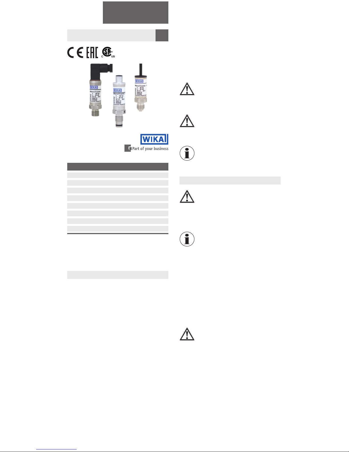
Circular connector M12 x 1 (4-pin)
2-wire 3-wire
UB
0V
S+-
Cable outlet, 2 m
2-wire 3-wire
UBbrown brown
0V green green
S+- white
43
12
Angular connector DIN 175301-803 C
2-wire 3-wire
UB
0V
S+-
5.2 Packaging
Do not remove packaging until just before mounting.
during transport (e.g. change in installation site, sending
for repair).
5.3 Storage
Permissible conditions at the place of storage:
Avoid exposure to the following factors:
Proximity to hot objects
Mechanical vibration, mechanical shock (putting it
down hard)
atmospheres
packaging is not available, pack and store the instrument
as described below:
Place the instrument, along with the shock-absorbent
material, in the packaging.
days), place a bag containing a desiccant inside the
packaging.
WARNING!
Before storing the instrument (following opera-
tion), remove any residual media.This is of
particular importance if the medium is hazard-
ous to health, e.g. caustic, toxic, carcinogenic,
radioactive, etc.
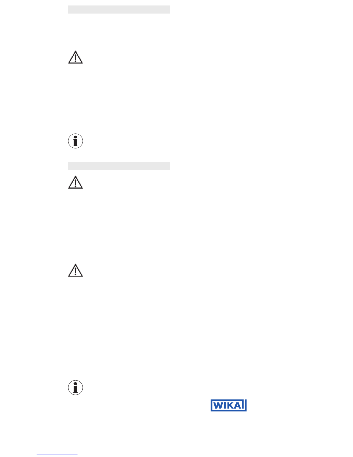
6. Commissioning, operation
CAUTION!
Prior to commissioning, the pressure transmit-
ter must be subjected to a visual inspection.
Check the diaphragm of the process
connection for any damage.
Only use the pressure transmitter if it is in
perfect condition with respect to safety.
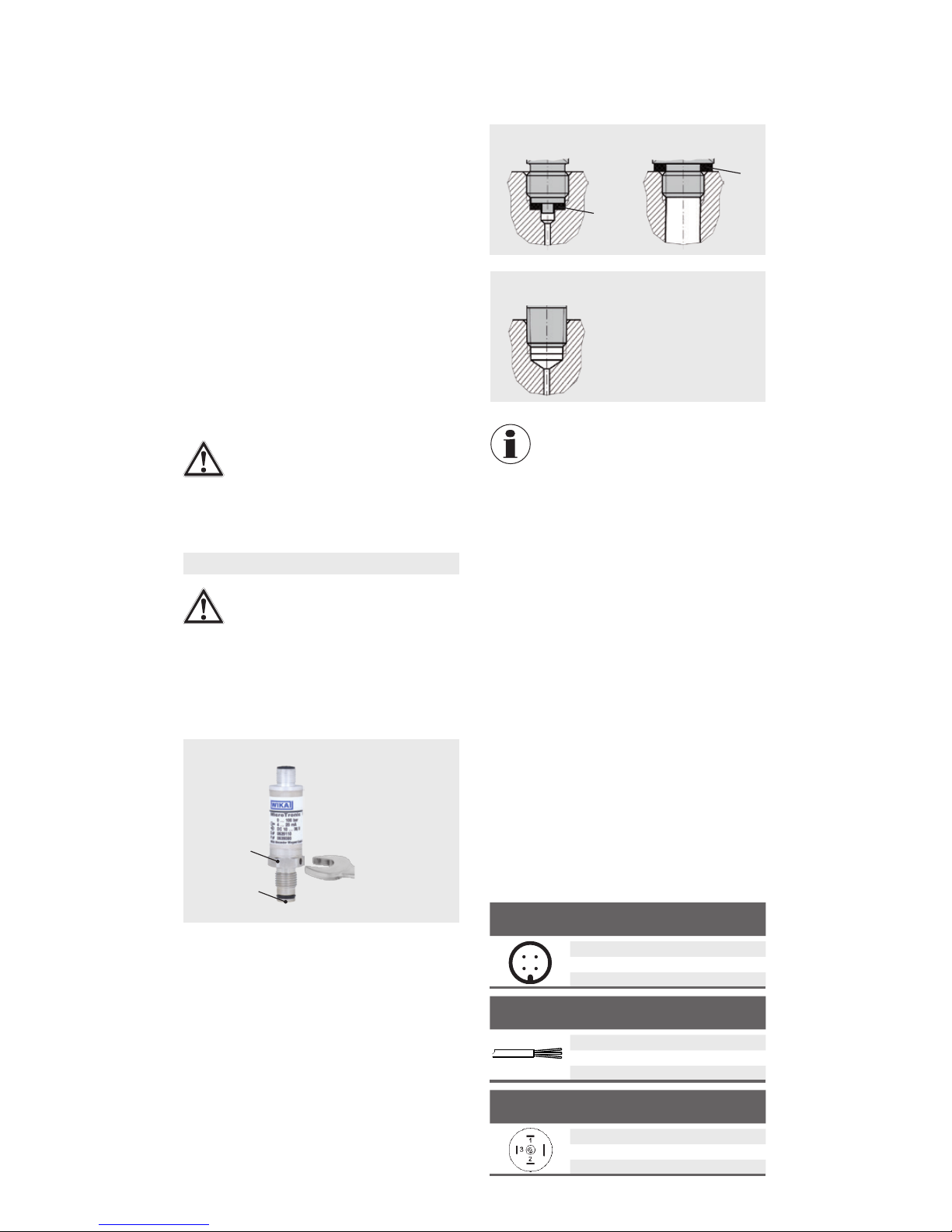
6.1 Mechanical mounting
Flush diaphragm
Sealing
Correct sealing of the process connections with parallel
threads at the sealing face must be made using suita-
sealing of tapered threads (e.g. NPT threads) is made by
providing the thread with additional sealing material such
6.2 Electrical mounting
The instrument must be grounded via the process
connection!
For instruments with voltage output, use shielded
leave the building, earth the shield at least at one end
of the cable.
at low voltages, which are separated from the power
recommended; alternatively protective measures from
America: The connection can be made in line with
-
ance with CEC (Canadian Electrical Code) or NEC
(National Electrical Code).
of the plug. Make sure that the cable gland of the
present and undamaged.Tighten the threaded connec-
tion and check that the seal is correctly seated, in order
to ensure the ingress protection.
For cable outlets, make sure that no moisture enters at
the cable end.
Remove the protection cap not until shortly before
installation.
Ensure that the diaphragm of the process connection
is not damaged during installation.
The sealing faces at the pressure transmitter and the
measuring point always have to be clean.
Only ever screw in, or unscrew, the instrument via
element as a working surface.
The correct torque depends on the dimensions of the
process connection, the gasket used (form/material)
and the measuring range (see illustration).
When screwing in, do not cross the threads.
For information on tapped holes and welding sockets,
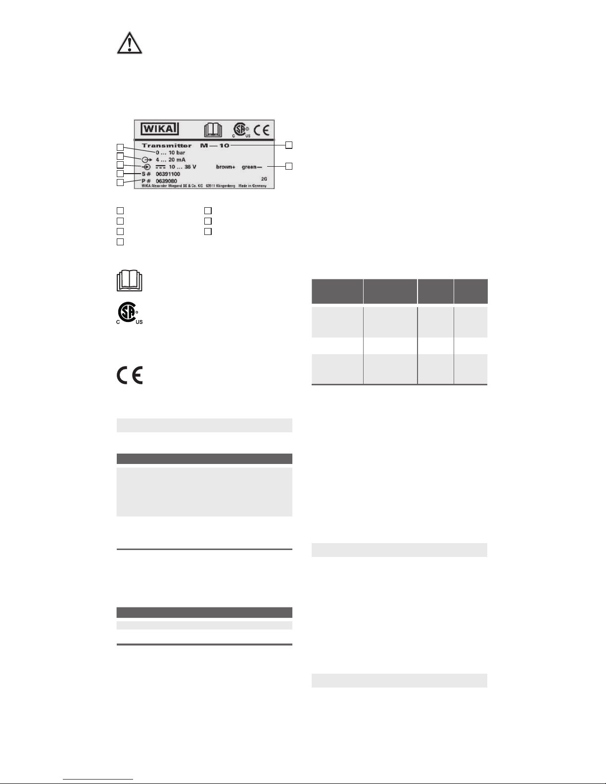
Connection diagrams
Maximum torque
Example, model M-11
Parallel thread
Tapered thread
NPT, R and PT