WIKA T31 User manual

Contents
1 Models
2 Safety
warnings
3 Mounting
4 Electrical connections
5 Maintenance
6 Notes for mounting and
operating in hazardous area
7 Safety-engineering values
8 Declaration of conformity
1 Models
2 Safety warnings
1 Models
2 Safety
warnings
When mounting, initiating and operating
thesetransmittersitisimportanttoobserve
the safety precautions and regulations
(e.g. IEC 60
364-6-61).
Nonobservance of the applicable regula-
tions may cause severe injury to persons
or damage to equipment.
Onlystaff with suitable qualification should
work with these transmitters.
We draw your attention to the following
which must be observed with transmitters
with Ex protection:
l
Observe the applicable regulations for
the use of Ex-class instruments (e.g.:
EN 50
014, EN 50
020, EN 50
021,
EN 50
284).
l
Observe the notes for mounting and
operating in hazardous area described
in section 6
.
l
It is forbidden to use a transmitter that
is damaged externally.
l
Repairs are forbidden.
Operating Instructions
Temperature Transmitter Model T31
Alexander-Wiegand-Straße 30
63911 Klingenberg
/
Germany
Phone (
+49) 93
72
/
132-0
Fax (
+49) 93
72
/
132-406
E-Mail [email protected]
www.wika.de
AlexanderWiegand GmbH & Co.KG
Specifications according to
WIKA
data sheet T
E 31.01.
Technical alteration rights observed.
Issue: May 2006
2294851.03 05/2006 D
+
GB T31
Issue: May 2006 Page 1 of 2
Operating Instructions
Note
Before initial operation check the suitabil-
ity for the intended application.
In particular, it is important to fulfill the am-
bientandoperation conditions as specified
in the
WIKA data sheet
TE 31.01
.
5 Maintenance
The temperature transmitters described
here are totally maintenance-free
!
The electronics are completely encap-
sulated and incorporate no components
which could be repaired or replaced.
4.3 Connect 4
...
20
mA
-
loop
The electrical connection is made
through the terminals
j
and
i
.
4
...
20 mA
-
loop
Input
4
...
20 mA
-
loop
Input
4.2 Input
Pt100 3 wire3.2 Mounting in connecton head
Insert the measuring insert with the
mounted transmitter in the protective
sheath and affix in the connecting head
using screws in pressure springs.
3.1 Mounting on measuring insert
The transmitter can be mounted on the cir-
cular plate of the measuring insert using
two countersunk head M
3 screws per
DIN EN 2009
.
Appropriate threaded inserts have been
press-fitted in the underside of the case.
Assumingthecountersinking is carriedout
correctly, the permissible screw length can
be calculated as follows:
l
max.
= s + 4
mm
Dimensions in mm:
l
max.
length of screw
s thickness of circular plate
Check the screw length before affixing the
transmitter to the measuring insert:
stick the screw in the circular plate
and verify additional length of 4 mm
!
Circular plate
WARNING
Do not exceed the maximum allowable
screw length
!
The transmitter will be demaged if the
screws are screwed further than
4
mm
into the bottom of the transmitter.
3 Mounting
3 Mounting
3.0 General
These transmitters are designed to be
mounted on a measuring insert in a
DIN
connecting head with
form B.
The connecting wires of the measuring in-
sert must be approx. 40
mm long and in-
sulated.
Mounting example:
3.1 Mounting on measuring insert
3.2 Mounting in connection head 4.3
Connect 4
...
20
mA
-
loop
5 Maintenance
4 Electrical connections
4 Electrical connections
! ! !
Important
! ! !
In the case of the transmitters described
here there is an internal galvanic connec-
tion between the sensor input and ana-
logue output.
No external conducting is to be made (for
example, by earthing) between the con-
nected temperature sensor and analogue
output
!
4.0 General
Thetransmittershaveconnecting terminals
for electrical connection.
We recommend the use of crimped con-
nector sleeves in the case of flexible leads.
4.1 Input
Pt100 2 wire
Set a jumper between the input terminals
and
. Otherwise the transmitter sig-
nals a sensor burnout and sets the output
signal ≥22.5 mA.
l
maximumpermissibleterminalvoltage:
30
V
l
maximum permissible load R
A
(dependentuponthelooppowersup-
ply voltage U
B
)
925
ΩΩ
ΩΩ
Ωat 30
Vpower supply U
B
625
ΩΩ
ΩΩ
Ωat 24
Vpower supply U
B
R
A
≤(U
B
- 11.5 V ) / 0.02 A
with R
A
in Ωand U
B
in V
Load diagramm
The permissible load R
A
dependent
upon the loop power supply voltage U
B
.
0 11.5 20 24 30
voltage
U
B
in
V à
925
625
0
load R
A
in Ω
à
TemperatureTransmitter ModelT31
Head mounting Ex protection
T31.10. 1P0 without
1P2 II 1G EEx ia
1P4 II 2G EEx ib
1P9 II 3G EExnL/ nA
6 Notes for mounting and
operating in hazardous area
6.0 General
Use only such a transmitter in a hazard-
ous area that have the corresponding
approval for this hazardous area.
The transmitter Model T31.10.1P
2
correspond to ignition protection type
intrinsically safe apparatus
II 1G EEx ia IIC T4
/
T5
/
T6.
The transmitter Model T31.10.1P
4
correspond to ignition protection type
intrinsically safe apparatus
II 2G EEx ib IIC T4
/
T5
/
T6.
The transmitter Model T31.10.1P
9
correspond
to ignition protection type
energy-limited
apparatus
II 3G EEx nL IIC T4
/
T5
/
T6
and to ignition protection type
non-sparking
apparatus
II 3G EEx nA IIC T4
/
T5
/
T6.
Model, Ex protection class, Approval
No. and Symbol are stated on the
rating plate.
Example:
T31.10.1P2
II 1G EEx ia IIC T4
/
T5
/
T6
DMT 02 ATEX E 106 X
6 Notes for mounting and operating in hazardous area
Operating Instructions TemperatureTransmitter ModelT31 Issue: May 2006 Page 2 of 2
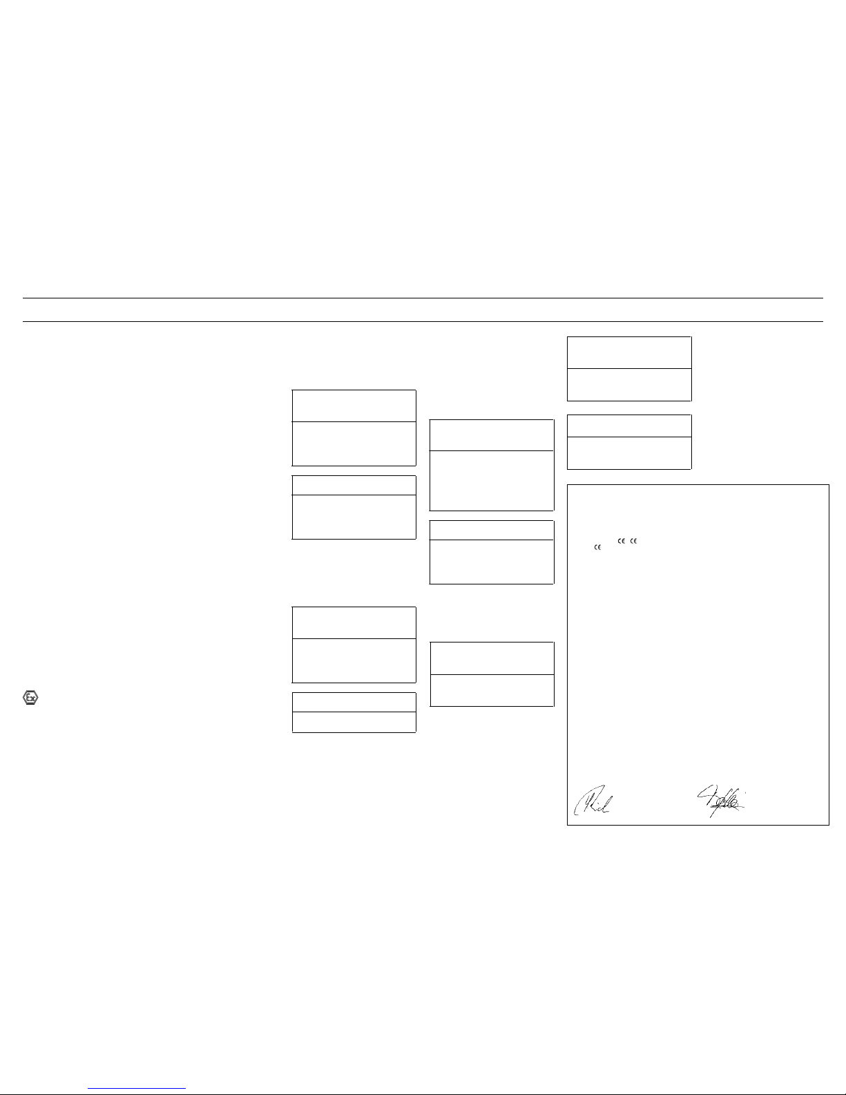
8 Declaration of conformity
T31.10.1P
2II 1G EEx ia IIC
T31.10.1P
4II 2G EEx ib IIC
C
sensor
+ C
line
<
C
O
C
O
= 10 µF
L
sensor
+ L
line
<
L
O
L
O
=3mH
T31.10.1P
9II 3G EEx nL/nA IIC
C
sensor
+ C
line
<
C
O
C
O
= 1000 µF
L
sensor
+ L
line
<
L
O
L
O
= 1000 mH
7 Safety-engineering values
EG-Konformitäts-
erklärung EC Declaration of
Conformity Déclaration de
ConformitéCE
Dokument Nr.: Document No.: Document No.:
11134755.01 11134755.01 11134755.01
Wir erklären, dass die mit
gekennzeichneten Produkte We declare that the
marked products Nous déclarons que les appareils
marqués
Typen: Models: Types:
T31.10.xxx T31.10.xxx T31.10.xxx
Beschreibung: Description: Description:
Analoger Temperatur-Transmitter,
Chemieausführung, Kopfmontage Analogue temperature transmitter,
Process Industries Series, head
mounting
Transducteur de température, Série
chimie, pour montage dan lélés de
sondes
gemäß gültigem Datenblatt: according to the valid data-sheet: selon fiche technique valide:
TE 31.01 TE 31.01 TE 31.01
die grundlegenden Anforderungen
der folgenden Richtlinien und
Normen erfüllen:
are in conformity with the essential
requirements of the directives and
standards:
sont conformes aux exigences
essentielles de les directives et
normes :
1) 89/336/EWG (EMV) 1) 89/336/EEC (EMC) 1) 89/336/CEE (CEM)
EN 61326:1997 +A1:98 +A2:01 EN 61326:1997 +A1:98 +A2:01 EN 61326:1997 +A1:98 +A2:01
2) 94/9/EG (ATEX) (1) 2) 94/9/EC (ATEX) (1) 2) 94/9/CE (ATEX) (1)
T31.10.1Px T31.10.1Px T31.10.1Px
EN 50014:1997 +A1:98 +A2:99 EN 50014:1997 +A1:98 +A2:99 EN 50014:1997 +A1:98 +A2:99
EN 50020:1994 EN 50020:1994 EN 50020:1994
EN 50284:1999 EN 50284:1999 EN 50284:1999
(1) EG-Baumusterprüfbescheinigung
DMT 02 ATEX E 106 X von EXAM
BBG Prüf- und Zertifizier GmbH,
Bochum (Reg.-Nr. 0158).
(1) EC-type-examination certificate
DMT 02 ATEX E 106 X of EXAM BBG
Prüf- und Zertifizier GmbH, Bochum
(reg. no. 0158).
(1) Attestation d’examen CE de type
DMT 02 ATEX E 106 X de EXAMBBG
Prüf- und Zertifizier GmbH, Bochum
(reg. no. 0158).
3) 94/9/EG (ATEX) 3) 94/9/EC (ATEX) 3) 94/9/CE (ATEX)
T31.10.009 T31.10.009 T31.10.009
EN 50021:1999 EN 50021:1999 EN 50021:1999
WIKA Alexander Wiegand GmbH & Co. KG
Klingenberg, 2006-05-08
Geschäftsbereich TRONIC
Company division TRONIC
Ressort TRONIC
Qualitätsmanagement TRONIC
Quality management TRONIC
Management de la qualitéTRONIC
i. V. Stefan Richter i. A. Thomas Gerling
6.1 Special conditions for
safe use
6.1.1 Mounting in the hazardous area
T31.**.**2/T31.**.**4:Transmitters in a ha-
zardous area are supplied only with asso-
ciated intrinsically safe apparatus that are
approved for this hazardous area. These
transmitters must be mounted in a case
that must at least correspond to following
ingress protection IP 20 according to EN
60 529 / IEC 529.
T31.**.**9 (Use as energy-limited equip-
ment II 3G EEx nL): The supply current
circuit must fulfil the requirements for igni-
tion protection type II 3G EEx nL energy-
limited (EN 50 021). These transmitters
must be mounted in a case that must at
least correspond to following ingress pro-
tection IP 54 according to EN 60 529 / IEC
529.
T31.**.**9 (Use as non-incentive equip-
ment II 3G EEx nA): Disconnection of po-
wer supply is forbidden inside the hazar-
dousarea.Whenconnectingordisconnec-
ting the terminals ensure the power supp-
ly is disconnected outside the hazardous
area.These trans-
mitters must be mounted in a case that
must at least correspond to following in-
gress protection IP 54 according to EN 60
529 / IEC 529.
When during use in circuits with the safety
class nA (non-incendive) the permissible
connected loads have been exceeded for
a short term
1)
, the use of these transmit-
ters in circuits with the safety class EEx nL
(energy limited) is not permissible any
more.
1)
When the transmitters are used in circuits
with the safety class nA, it is permissible to
exceed the maximum supply voltage by up to
40 % for a short term.
6.1.2 Operating transmitter in Zone 0
The temperature transmitter may be oper-
ated only in areas that require apparatus
of category 1 when following atmospheric
conditions exist:
temperature: -20
°C ... +60
°C
pressure: 0.8 bar ... 1.1 bar
6.1.3 Operating the transmitter in
Zone 1 and Zone 2
The transmitter may be used only in the
following ambient temperature range ac-
cording to the temperature class:
T31.10.1P
2II 1G EEx ia
T31.10.1P
4II 2G EEx ib
T4 : -
50
°C ≤T
a
≤+
85
°C
T5 : -
50
°C ≤T
a
≤+
75
°C
T6 : -
50
°C ≤T
a
≤+
60
°C
T31.10.1P
9II 3G EEx nL/nA
T4 : -
40
°C ≤T
a
≤+
85
°C
T5 : -
40
°C ≤T
a
≤+
70
°C
T6 : -
40
°C ≤T
a
≤+
50
°C
7 Safety-engineering values
7.1
Power Supply / 4 ... 20 mA-
loop
The following safe technical maximum val-
ues must not be exceeded:
T31.10.1P
2II 1G EEx ia
T31.10.1P
4II 2G EEx ib
Voltage U
i
= DC 30 V
Current I
i
= 100 mA
Power P
i
= 800 mW
T31.10.1P
9II 3G EEx nL/nA
Voltage U
i
= DC 30 V
Following have an outward effect at the
connection terminals
j
und
i
of the
transmitter
Model T31.10.1P
2and T31.10.1P
4:
effective internal capacity C
i
= 6.2 nF
effective internal inductivity L
i
= 110 µH
Model T31.10.1P
9:
effective internal capacity C
i
= 1.2 nF
effective internal inductivity L
i
= 100 µH
7.2 Sensor (terminal 1 to 3)
Connect the sensor according to section
4
to the terminals
,
and
.
The connected sensor must not warm up
inadmissablyaccordingtothetemperature
class of the respective hazardous area for
thefollowingvalues forvoltage,current and
power:
T31.10.1P
2II 1G EEx ia
T31.10.1P
4II 2G EEx ib
maximum possible values
U
O
= DC 6.4 V
I
O
= 100 mA
P
O
= 426 mW
T31.10.1P
9II 3G EEx nL/nA
effective values during operation
U
O
= DC 2.5 V
I
O
= 1.2 mA
The sum of the values of the connected
sensor and the connection line must not
exceed the following values for the maxi-
mum permissible capacity and inductivity:
T31.10.1P
2II 1G EEx ia IIB
T31.10.1P
4II 2G EEx ib IIB
C
sensor
+ C
line
<
C
O
C
O
= 500 µF
L
sensor
+ L
line
<
L
O
L
O
= 10 mH
(to be continued, see next column)
Table of contents
Other WIKA Transmitter manuals


Popular Transmitter manuals by other brands

Sony
Sony WLL-CA55 Maintenance manual

HumanTechnik
HumanTechnik RadioLight operating instructions

ARTEX
ARTEX ELT 4000S Description, operation, installation and maintenance manual

DLO
DLO TransCast FM user manual

CHERUBINI
CHERUBINI Domotic TX instructions

Tactical technologies
Tactical technologies TX-600 Operating instruction

Endress+Hauser
Endress+Hauser Proline 300 Brief operating instructions

BASI
BASI BPT50-A Operation manual

JUMO
JUMO AQUIS 500 CR operating instructions

Emerson
Emerson Rosemount 3051HT quick start guide

Landmark Audio Technologies
Landmark Audio Technologies Personal Listening System instruction manual

Intelix
Intelix DIGI-VGASD2-T8 installation guide


