WIKA IPT-1 series User manual

Operating Instructions
Process pressure transmitter IPT-1*
4 … 20 mA/HART
metallic sensor
Version 3.0

2
Contents
WIKA Operating Instructions - Process pressure transmitter IPT-1*
Contents
1 About this document
1.1 Function ........................................................................................................................... 4
1.2 Target group ..................................................................................................................... 4
1.3 Symbols used................................................................................................................... 4
2 For your safety
2.1 Authorised personnel ....................................................................................................... 5
2.2 Appropriate use................................................................................................................ 5
2.3 Warning about incorrect use............................................................................................. 5
2.4 General safety instructions............................................................................................... 5
2.5 Safety label on the instrument .......................................................................................... 6
2.6 CE conformity................................................................................................................... 6
2.7 Measuring range - permissible process pressure............................................................. 6
2.8 FulllmentofNAMURrecommendations ......................................................................... 6
2.9 Safety instructions for Ex areas ........................................................................................ 6
2.10 Safety instructions for oxygen applications....................................................................... 6
3 Product description
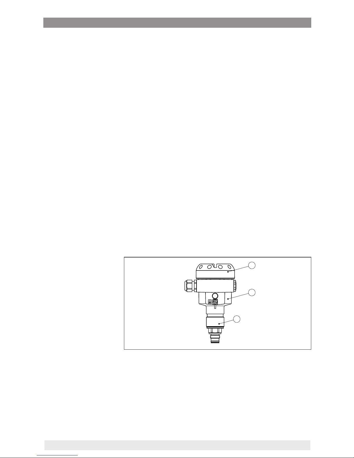
3.1 Conguration.................................................................................................................... 7
3.2 Principle of operation........................................................................................................ 8
3.3 Operation ......................................................................................................................... 8
3.4 Packaging, transport and storage..................................................................................... 8
4 Mounting
4.1 General instructions ....................................................................................................... 10
4.2 Mounting instructions ..................................................................................................... 12
4.3 Installation procedure..................................................................................................... 12
5 Connecting to power supply
5.1 Preparing the connection ............................................................................................... 13
5.2 Connection procedure.................................................................................................... 14
5.3 Wiring plan, single chamber housing.............................................................................. 15
5.4 Wiring plan, double chamber housing ............................................................................ 17
5.5 Wiring plan, double chamber housing Ex d .................................................................... 19
5.6 Wiring plan, external housing with version IP 68 (25 bar) ............................................... 21
5.7 Switch-on phase............................................................................................................. 22
6 Set up with the display and adjustment module
6.1 Short description ............................................................................................................ 24
6.2 Insert display and adjustment module............................................................................ 24
6.3 Adjustment system......................................................................................................... 25
6.4 Setup steps .................................................................................................................... 26
6.5 Menu schematic............................................................................................................. 34
6.10 Saving the parameter adjustment data........................................................................... 36
7 Set up with PACTware and other adjustment programs
7.1 Connect the PC.............................................................................................................. 37
7.2 Parameter adjustment with PACTware............................................................................ 37
7.3 Parameter adjustment with AMS™ and PDM................................................................. 38
7.4 Saving the parameter adjustment data........................................................................... 38
8 Maintenanceandfaultrectication

3
Contents
WIKA Operating Instructions - Process pressure transmitter IPT-1*
8.1 Maintenance .................................................................................................................. 39
8.2 Rectify faults................................................................................................................... 39
8.3 Instrument repair ............................................................................................................ 40
9 Dismount
9.1 Dismounting steps.......................................................................................................... 41
9.2 Disposal ......................................................................................................................... 41
10 Supplement
10.1 Technical data ................................................................................................................ 42
10.2 Dimensions .................................................................................................................... 49
Supplementary documentation
Information:
Supplementary documents appropriate to the ordered version come
withthedelivery.Youcanndthemlistedinchapter"Product descrip-
tion".
Instructions manuals for accessories and replacement parts
Tip:
ToensurereliablesetupandoperationofyourIPT-1*,weoeracces-
sories and replacement parts.The corresponding documentations
are:
• Operatinginstructionsmanual"External display and adjustment
unit"
Editing status: 2015-04-29

4
1 About this document
WIKA Operating Instructions - Process pressure transmitter IPT-1*
1 About this document
1.1 Function
This operating instructions manual provides all the information you
need for mounting, connection and setup as well as important instruc-
tionsformaintenanceandfaultrectication.Pleasereadthisinforma-
tion before putting the instrument into operation and keep this manual
accessible in the immediate vicinity of the device.
1.2 Target group
This operating instructions manual is directed to trained specialist
personnel.The contents of this manual should be made available to
these personnel and put into practice by them.
1.3 Symbols used
Information, tip, note
This symbol indicates helpful additional information.
Caution: If this warning is ignored, faults or malfunctions can result.
Warning: If this warning is ignored, injury to persons and/or serious
damage to the instrument can result.
Danger: If this warning is ignored, serious injury to persons and/or
destruction of the instrument can result.
Ex applications
This symbol indicates special instructions for Ex applications.
SIL applications
This symbol indicates instructions for functional safety which must be
taken into account particularly for safety-relevant applications.
• List
The dot set in front indicates a list with no implied sequence.
→ Action
This arrow indicates a single action.
1 Sequence of actions
Numberssetinfrontindicatesuccessivestepsinaprocedure.
Battery disposal
This symbol indicates special information about the disposal of bat-
teries and accumulators.

5
2 For your safety
WIKA Operating Instructions - Process pressure transmitter IPT-1*
2 For your safety
2.1 Authorised personnel
Mount and set up the pressure transmitter only if you know the appli-
cablenationalregulationsandhavetheappropriatequalication.You
must be aquainted with the regulations and instructions for hazard-
ous areas, measurement and control technology as well as electrical
circuitsbecausethepressuretransmitteris"electricalequipment"
accordingtoEN50178.Dependingontheapplicationconditions,it
is necessary that you have appropriate knowledge, e.g. concerning
corrosive products or high pressure.
2.2 Appropriate use
IPT-1* is a pressure transmitter for measurement of gauge pressure,
absolute pressure and vacuum.
Youcannddetailedinformationabouttheareaofapplicationin
chapter"Product description".
Operational reliability is ensured only if the instrument is properly
usedaccordingtothespecicationsintheoperatinginstructions
manual as well as possible supplementary instructions.
For safety and warranty reasons, any invasive work on the device
beyond that described in the operating instructions manual may be
carried out only by personnel authorised by the manufacturer. Arbi-
traryconversionsormodicationsareexplicitlyforbidden.
2.3 Warning about incorrect use
Inappropriate or incorrect use of the instrument can give rise to
application-specichazards,e.g.vesseloverllordamagetosystem
components through incorrect mounting or adjustment.
2.4 General safety instructions
This is a state-of-the-art instrument complying with all prevailing
regulations and guidelines. The instrument must only be operated in a
technicallyawlessandreliablecondition.Theoperatorisresponsible
for the trouble-free operation of the instrument.
During the entire duration of use, the user is obliged to determine the
compliance of the necessary occupational safety measures with the
current valid rules and regulations and also take note of new regula-
tions.
The safety instructions in this operating instructions manual, the na-
tional installation standards as well as the valid safety regulations and
accident prevention rules must be observed by the user.
For safety and warranty reasons, any invasive work on the device
beyond that described in the operating instructions manual may be
carried out only by personnel authorised by the manufacturer. Arbi-
traryconversionsormodicationsareexplicitlyforbidden.
The safety approval markings and safety tips on the device must also
be observed.

6
2 For your safety
WIKA Operating Instructions - Process pressure transmitter IPT-1*
2.5 Safety label on the instrument
The safety approval markings and safety tips on the device must be
observed.
2.6 CE conformity
ThisdevicefulllsthelegalrequirementsoftheapplicableECguide-
lines.ByattachingtheCEmark,weprovideconrmationofsuccess-
ful testing.
2.7 Measuring range - permissible process
pressure
Due to the application, a measuring cell with a measuring range
higherthanthepermissiblepressurerangeoftheprocessttingmay
have been integrated. The permissible process pressure is stated with
"Processpressure"onthetypelabel,seechapter3.1"Conguration".
For safety reasons, this range must not be exceeded.
2.8 FulllmentofNAMURrecommendations
ThedevicefulllstherequirementsoftheapplicableNAMURrecom-
mendations.
2.9 Safety instructions for Ex areas
PleasenotetheEx-specicsafetyinformationforinstallationandop-
eration in Ex areas. These safety instructions are part of the operating
instructions manual and come with the Ex-approved instruments.
2.10 Safety instructions for oxygen applications
For instruments in oxygen applications the special instructions in
chapters"Storage and transport","Mounting"aswellas"Technical
data"under"Process conditions"mustbenoted.Furthermorethevalid
national regulations, implementation instructions and memorandums
of the professional assocations must be noted.

7
3 Product description
WIKA Operating Instructions - Process pressure transmitter IPT-1*
3 Product description
3.1 Conguration
The scope of delivery encompasses:
• IPT-1* process pressure transmitter
• Documentation
– This operating instructions manual
– Testcerticateforpressuretransmitters
– SafetyManual"IPT-1* - 4 … 20 mA/HART two-wire"(optional)
– Operatinginstructionsmanual"Display and adjustment mod-
ule"(optional)
– Supplementaryinstructionsmanual"Plug connector for con-
tinuously measuring sensors"(optional)
– Ex-specic"Safety instructions"(withExversions)
– ifnecessary,furthercerticates
Instrumentsintheversion"Oil and grease-free for oxygen applica-
tions"areequippedwithasupplementarylabel.Thesupplementary
label contains instructions on oil and grease-free parts of the instru-
ment.
The IPT-1* consists of the components:
• Processttingwithmeasuringcell
• Housing with electronics, optionally available with plug connector
• Housing cover, optionally available with display and adjustment
module
Thecomponentsareavailableindierentversions.
1
2
3
Fig. 1: Example of a IPT-1* with manometer connection G½ according to
EN 837 and Alu housing
1 Housing cover with integrated display and adjustment module (optional)
2 Housing with electronics
3 Process tting with measuring cell
Thetypelabelcontainsthemostimportantdataforidenticationand
use of the instrument:
• Instrument type
• Article and serial number device
Scope of delivery
Supplementary label
"Oil and grease-free for
oxygen applications"
Constituent parts
Type label

8
3 Product description
WIKA Operating Instructions - Process pressure transmitter IPT-1*
• Technical data: Measuring range, process pressure, process tem-
perature, signal output, voltage supply, protection, protection class
• Order number
• Article number, documentation
• SILidentication(withSILratingexworks)
3.2 Principle of operation
IPT-1* is a pressure transmitter for measurement of overpressure,
absolute pressure or vacuum. Measured products are gases, vapours
and liquids in measuring ranges up to 4000 bar (400 MPa); with front-
ushversionalsoviscousliquidsinmeasuringrangesupto600bar
(60 MPa).
The process pressure acts on the sensor element via the stainless
steel diaphragm and an internal transmission liquid.This causes a
resistance change which is converted into a corresponding output
signal and outputted as a measured value. With measuring ranges
up to 16 bar a pieoresistive sensor element is used, with measuring
ranges from 25 bar a strain gauge (DMS) sensor element.
4 … 20 mA/HART two-wire electronics for voltage supply and meas-
ured value transmission on the same cable.
Thesupplyvoltagerangecandierdependingontheinstrumentver-
sion.Theexactrangeisstatedinchapter"Technical data".
The backlight of the display and adjustment module is powered by
the sensor. The prerequisite for this is a supply voltage at a certain
level.Theexactvoltagespecicationsarestatedinchapter"Technical
data".
3.3 Operation
The instrument can be adjusted with the following adjustment media:
• With the display and adjustment module
• the suitable WIKA DTM in conjunction with an adjustment software
according to the FDT/DTM standard, e.g. PACTware and PC
• Withmanufacturer-specicadjustmentprogramsAMS™orPDM
• With a HART handheld
The entered parameters are generally saved in IPT-1*, optionally also
in the display and adjustment module or in PACTware.
3.4 Packaging, transport and storage
Your instrument was protected by packaging during transport. Its
capacity to handle normal loads during transport is assured by a test
based on ISO 4180.
The packaging of standard instruments consists of environment-
friendly, recyclable cardboard. For special versions, PE foam or PE
foil is also used. Dispose of the packaging material via specialised
recycling companies.
Application area
Functional principle
Voltage supply
Packaging

9
3 Product description
WIKA Operating Instructions - Process pressure transmitter IPT-1*
Caution:
Instruments for oxygen applications are sealed in PE foil and provided
withalabel"Oxygen!UsenoOil".Removethisfoiljustbeforemount-
ingtheinstrument!Seeinstructionunder"Mounting".
Transport must be carried out in due consideration of the notes on the
transportpackaging.Nonobservanceoftheseinstructionscancause
damage to the device.
The delivery must be checked for completeness and possible transit
damage immediately at receipt. Ascertained transit damage or con-
cealed defects must be appropriately dealt with.
Uptothetimeofinstallation,thepackagesmustbeleftclosedand
stored according to the orientation and storage markings on the
outside.
Unlessotherwiseindicated,thepackagesmustbestoredonlyunder
the following conditions:
• Notintheopen
• Dry and dust free
• Notexposedtocorrosivemedia
• Protected against solar radiation
• Avoiding mechanical shock and vibration
• Storageandtransporttemperatureseechapter"Supplement -
Technical data - Ambient conditions"
• Relative humidity 20 … 85 %
Transport
Transport inspection
Storage
Storage and transport
temperature

10
4 Mounting
WIKA Operating Instructions - Process pressure transmitter IPT-1*
4 Mounting
4.1 General instructions
Make sure that all parts of the instrument coming in direct contact
with the process, especially the sensor element, process seal and
processtting,aresuitablefortheexistingprocessconditions,such
as process pressure, process temperature as well as the chemical
properties of the medium.
Youcanndthespecicationsinchapter"Technical data"andonthe
nameplate.
Toprotectthediaphragm,theprocessttingiscoveredbyaprotec-
tive cap.
Remove the protective cap just before installation so that the dia-
phragm will not get damaged. It is recommended to keep the cap and
use it again later for storage or transport.
Select an installation position you can easily reach for mounting and
connectingaswellaslaterretrottingofadisplayandadjustment
module.The housing can be rotated by 330° without the use of any
tools.You can also install the display and adjustment module in four
dierentpositions(eachdisplacedby90°).
Usetherecommendedcables(seechapter"Connecting to power
supply")andtightenthecablegland.
You can give your instrument additional protection against moisture
penetration by leading the connection cable downward in front of the
cableentry.Rainandcondensationwatercanthusdraino.Thisap-
plies mainly to outdoor mounting as well as installation in areas where
high humidity is expected (e.g. through cleaning processes) or on
cooled or heated vessels.
Fig. 2: Measures against moisture ingress
The ventilation of the electronics housing as well as the atmospheric
pressurecompensationforthemeasuringcellarerealisedviaalter
element in the area of the cable gland.
Suitability for the process
conditions
Diaphragm protection
Installation position
Moisture
Ventilation and pressure
compensation

11
4 Mounting
WIKA Operating Instructions - Process pressure transmitter IPT-1*
2
1
1
Fig. 3: Position of the lter element
1 Filter element
2 Blind plug
Caution:
Duetotheltereect,thepressurecompensationistimedelayed.
When opening/closing the housing cover quickly, the measured value
can change for a period of approx. 5 s by up to 15 mbar.
Information:
Makesurethatthelterelementisalwaysfreeofbuildupduring
operation. A high-pressure cleaner may not be used for cleaning.
Higher process temperatures mean often also higher ambient tem-
peratures.
1
2
Fig. 4: Temperature ranges
1 Process temperature
2 Ambient temperature
Make sure that the upper temperature limits for the environment of
electronicshousingandconnectioncablespeciedinchapter"Tech-
nical data"arenotexceeded.
Instrumentsintheversion"Oil and grease free for oxygen"should
be unpacked just before mounting. After the protective cover of the
processttinghasbeenremoved,thelabel"O2"ontheprocesstting
is visible.
Danger:
Avoidoil,greaseorcontamination.Explosiondanger!
Temperature limits
Oxygen applications

12
4 Mounting
WIKA Operating Instructions - Process pressure transmitter IPT-1*
4.2 Mounting instructions
IPT-1* functions in any installation position. It is mounted according to
thesamedirectivesasamanometer(DINEN839-2).1)
Information:
Werecommendusinglockttings,measuringinstrumentholdersand
siphons from the line of WIKA accessories.
4.3 Installation procedure
TomountIPT-1*,aweldedsocketisnecessary.Usecomponentsfrom
the line of WIKA mounting accessories.
→ Notetheapplicableweldingstandards(segmentweldingproce-
dure) when welding the socket.
Usethesealcorrespondingtotheinstrument:
• ProcessttingGD:Tesnitsealinfrontofthethread
- or -
Seal the thread with resistant seal material:
• ProcessttingGN
→ Screw IPT-1* into the welded socket. Tighten the hexagon on the
processttingwithasuitablewrench.Wrenchsize,seechapter
"Dimensionaldrawings".
Warning:
Thehousingmustnotbeusedtoscrewtheinstrumentin!Applying
tightening force can damage internal parts of the housing.
Usethesealsuitablefortherespectiveprocesstting.Youcannd
thecomponentsinthesupplementaryinstructionsmanual"Welded
socket and seals".
Installation position
Welding the socket
Sealing/Screwing in
Sealing/Installing hy-
gienicttings
1) Probablepositioncorrectionseechapter"Setupsteps".

13
5 Connecting to power supply
WIKA Operating Instructions - Process pressure transmitter IPT-1*
5 Connecting to power supply
5.1 Preparing the connection
Always keep in mind the following safety instructions:
• Connect only in the complete absence of line voltage
• If overvoltage surges are expected, overvoltage arresters should
be installed
In hazardous areas you must take note of the respective regulations,
conformityandtypeapprovalcerticatesofthesensorsandpower
supply units.
Power supply and current signal are transmitted via the same two-
wireconnectioncable.Thesupplyvoltagerangecandierdepending
ontheinstrumentversion.Theexactrangeisstatedinthe"Technical
data"inthe"Supplement".
Provide a reliable separation between the supply circuit and the
mainscircuitsaccordingtoDINEN61140VDE0140-1.
Keepinmindthefollowingadditionalinuencesontheoperating
voltage:
• Output voltage of the power supply unit can be lower under nomi-
nal load (with a sensor current of 20.5 mA or 22 mA in case of fault
message)
• Inuenceofadditionalinstrumentsinthecircuit(seeloadvaluesin
chapter"Technical data")
The instrument is connected with standard two-wire cable without
screen. If electromagnetic interference is expected which is above the
testvaluesofEN61326forindustrialareas,screenedcableshould
be used.
Usecablewithroundcross-section.Acableouterdiameterof
5…9mm(0.2…0.35in)ensuresthesealeectofthecablegland.
Ifyouareusingcablewithadierentdiameterorcross-section,
exchange the seal or use a suitable cable gland.
If screened cable is required, connect the cable screen on both ends
to ground potential. In the sensor, the screen must be connected
directly to the internal ground terminal.The ground terminal on the
outside of the housing must be connected to the potential equalisa-
tion (low impedance).
If potential equalisation currents are expected, the connection on the
processing side must be made via a ceramic capacitor (e. g. 1 nF,
1500 V).The low-frequency potential equalisation currents are thus
suppressed,buttheprotectiveeectagainsthighfrequencyinterfer-
ence signals remains.
Warning:
Considerablepotentialdierencesexistinsidegalvanicplantsaswell
as vessels with cathodic corrosion protection.Very large equalisa-
tioncurrentscanowthroughthecablescreenwhenthescreen
Notesafetyinstructions
Take note of safety
instructions for Ex
applications
Select power supply
Select connection cable
Cable screening and
grounding

14
5 Connecting to power supply
WIKA Operating Instructions - Process pressure transmitter IPT-1*
is grounded on both ends. To avoid this, the cable screen must be
connected to ground potential only on one end (inside the switch-
ing cabinet) in such applications.The cable screen must not be
connected to the internal ground terminal in the sensor and the outer
ground terminal on the housing nottopotentialequalisation!
Information:
The metallic parts of the instrument such as transmitter and process
ttingareconductivelyconnectedwiththeinnerandouterground
terminal on the housing.This connection exists either as a direct me-
tallic contact or via the shielding of the special connection cable on
instrumentswithexternalelectronics.Youcanndspecicationson
thepotentialconnectionswithintheinstrumentinchapter"Technical
data".
Take note of the corresponding installation regulations for Ex applica-
tions. In particular, make sure that no potential equalisation currents
owoverthecablescreen.Incaseofgroundingonbothsidesthis
can be achieved by the use of a capacitor or a separate potential
equalisation.
5.2 Connection procedure
Proceed as follows:
1. Unscrewthehousingcover
2. If a display and adjustment module is installed, remove it by turn-
ing it slightly to the left.
3. Loosen compression nut of the cable entry gland
4. Remove approx. 10 cm (4 in) of the cable mantle, strip approx.
1 cm (0.4 in) of insulation from the ends of the individual wires
5. Insert the cable into the sensor through the cable entry
6. Lift the opening levers of the terminals with a screwdriver (see
following illustration)
7. Insert the wire ends into the open terminals according to the wir-
ing plan
Select connection
cable for Ex applica-
tions

15
5 Connecting to power supply
WIKA Operating Instructions - Process pressure transmitter IPT-1*
Fig. 5: Connection steps 6 and 7
8. Press down the opening levers of the terminals, you will hear the
terminal spring closing
9. Check the hold of the wires in the terminals by lightly pulling on
them
10. Connect the screen to the internal ground terminal, connect the
outer ground terminal to potential equalisation
11. Tighten the compression nut of the cable entry gland. The seal
ring must completely encircle the cable
12. Screw the housing lid back on
Theelectricalconnectionisnished.
5.3 Wiring plan, single chamber housing
The following illustrations apply to the non-Ex as well as to the Ex-ia
version.

16
5 Connecting to power supply
WIKA Operating Instructions - Process pressure transmitter IPT-1*
567812
Display
I²C
2
1
4
3
Fig. 6: Electronics and terminal compartment, single chamber housing
1 Plug connector for service
2 Spring-loaded terminals for connection of the external display and adjust-
ment module
3 Ground terminal for connection of the cable screen
4 Spring-loaded terminals for voltage supply
I2C
Display
1
12 5678
Fig. 7: Wiring plan, single chamber housing
1 Voltage supply, signal output
Electronics and terminal
compartment
Wiring plan

17
5 Connecting to power supply
WIKA Operating Instructions - Process pressure transmitter IPT-1*
5.4 Wiring plan, double chamber housing
1
32
Display
12 5678
I²C
Fig. 8: Electronics compartment, double chamber housing
1 Plug connector for service
2 Internal connection cable to the connection compartment
3 Terminals for the external display and adjustment unit
1
2
3
Display
12 I2C
Fig. 9: Terminal compartment, double chamber housing
1 Spring-loaded terminals for voltage supply
2 Plug connector for service interface
3 Ground terminal for connection of the cable screen
Electronics compartment
Terminal compartment

18
5 Connecting to power supply
WIKA Operating Instructions - Process pressure transmitter IPT-1*
I2C
1
12
Fig. 10: Wiring plan, double chamber housing
1 Voltage supply, signal output
34
12
Fig. 11: Top view of the plug connector
1 Pin 1
2 Pin 2
3 Pin 3
4 Pin 4
Contact pin Colour connection ca-
ble in the sensor
Terminal, electronics
module
Pin 1 Brown 5
Pin 2 White 6
Pin 3 Blue 7
Pin 4 Black 8
Wiring plan
Plug M12 x 1 for external
display and adjustment
unit

19
5 Connecting to power supply
WIKA Operating Instructions - Process pressure transmitter IPT-1*
5.5 Wiring plan, double chamber housing Ex d
1
32
Display
12 5678
I²C
Fig. 12: Electronics compartment, double chamber housing
1 Plug connector for service
2 Internal connection cable to the connection compartment
3 Terminals for the external display and adjustment unit
1
2
12
Fig. 13: Connection compartment, Ex-d-ia double chamber housing
1 Spring-loaded terminals for power supply and cable screen
2 Ground terminal for connection of the cable screen
Electronics compartment
Terminal compartment

20
5 Connecting to power supply
WIKA Operating Instructions - Process pressure transmitter IPT-1*
1
1 2
Fig. 14: Wiring plan, Ex-d-ia double chamber housing
1 Voltage supply, signal output
34
12
Fig. 15: Top view of the plug connector
1 Pin 1
2 Pin 2
3 Pin 3
4 Pin 4
Contact pin Colour connection ca-
ble in the sensor
Terminal, electronics
module
Pin 1 Brown 5
Pin 2 White 6
Pin 3 Blue 7
Pin 4 Black 8
Wiring plan
Plug M12 x 1 for external
display and adjustment
unit
Other manuals for IPT-1 series
1
Table of contents
Other WIKA Transmitter manuals