WMF 5000S User manual

WMF 5000S
Service manual
KMT Technical Support
Revision: 03/2015
Rev. 01

Preface 2
Preface
This service manual contains the most important information that is relevant to typical service and maintenance activities.
If significant changes are made, then this document, along with the referenced attachments and related documents, will be updated and provided to registered
users for download in the service center.
Attachments.
WMF Dynamic Milk Setting instructions milk and foam
WMF 5000S setting instructions milk and foam, Easy Milk
WMF 5000S Software description part 1
WMF 5000S Software description part 2
WMF 5000S event and error list
Applicable documents
Customer documents
Planning information
User manual
Technician documents
Piping schematics
Electrical schematics
Wiring schematics
Spare parts lists
Technical circulars
Technical service instructions: These documents are subject to change. Please try to keep these documents up-to-date.
Planned contents which is awaiting implementation/remain unavailable appears in italics in the document.
Further detailed information are distributed in paper form as part of the face-to-face training sessions; however, they are not available for download
unencumbered.

Change history 3
Change history
Rev. 01 1st edition for series launch

Table of Contents 4
Table of Contents
Preface.............................................................................................................................................................................................................................................................. 2
Change history................................................................................................................................................................................................................................................. 3
Table of Contents............................................................................................................................................................................................................................................ 4
1Installation and commissioning........................................................................................................................................................................................................ 6
1.1Customers on-site connection requirements .........................................................................................................................................................................................................................6
1.2Hardware connection and preparatory work .........................................................................................................................................................................................................................7
1.2.1General tasks......................................................................................................................................................................................................................................................................................7
1.2.2Recommended water filter ...........................................................................................................................................................................................................................................................7
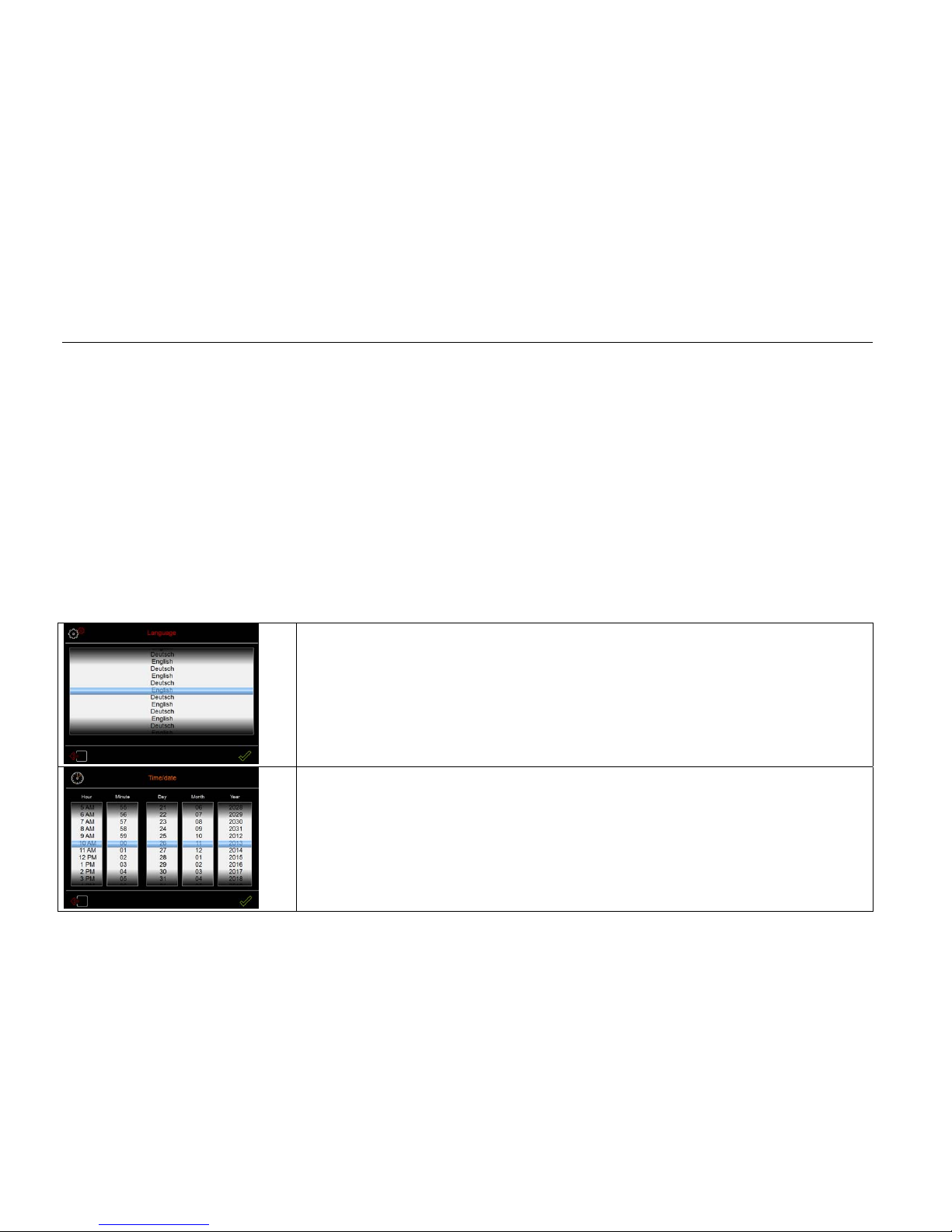
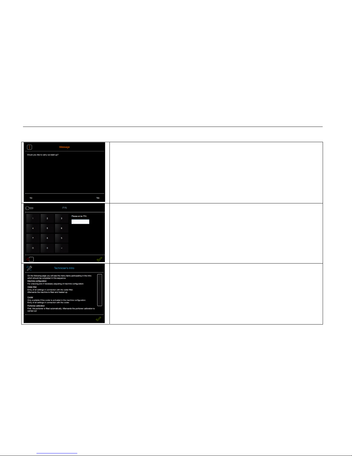
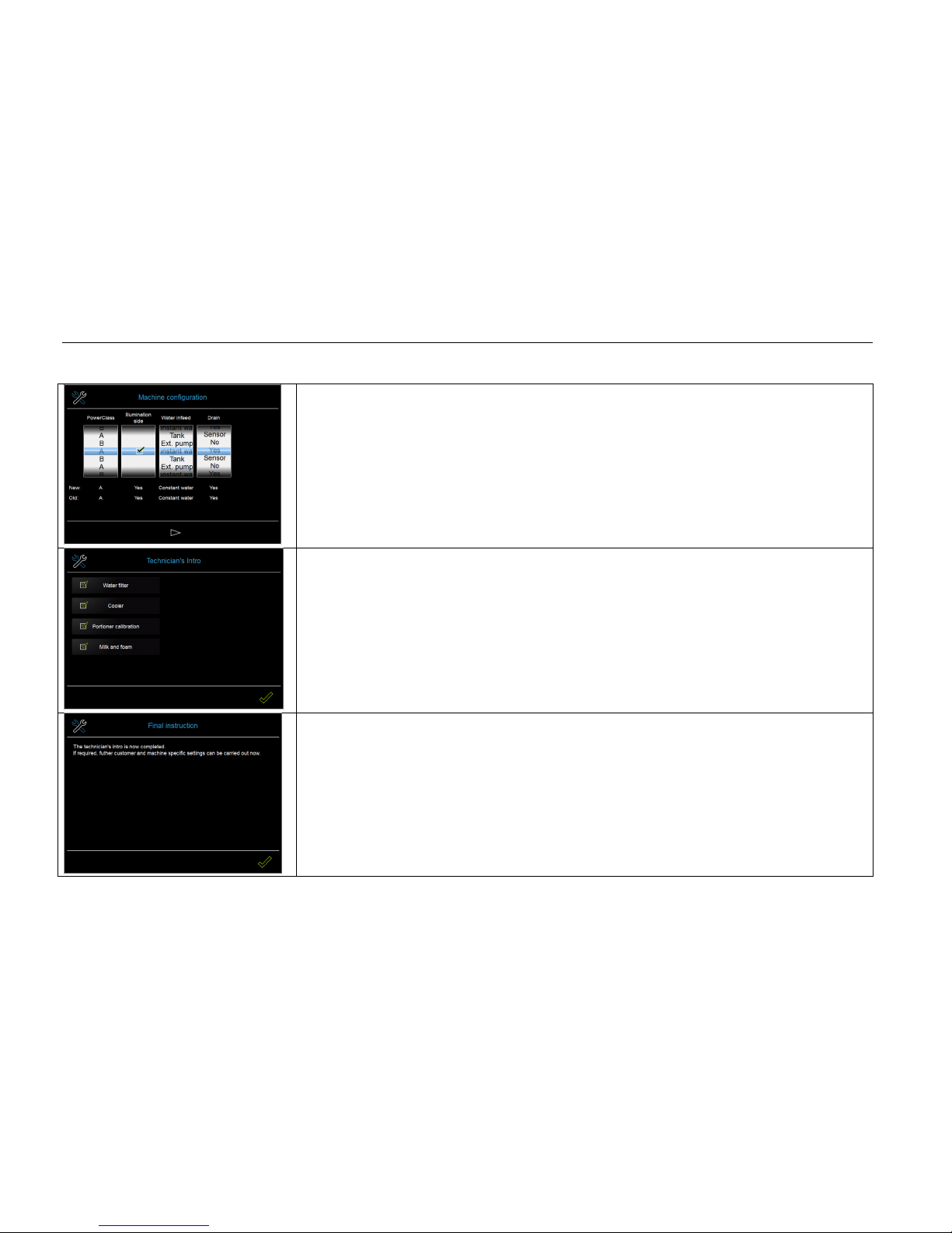
1.3Initial start-up with the aid of the technical information ................................................................................................................................................................................................8
1.3.1Goal of the technician information...........................................................................................................................................................................................................................................8
1.3.2Workflow, technician info: ...........................................................................................................................................................................................................................................................8
2Service................................................................................................................................................................................................................................................ 11
2.1Brewer............................................................................................................................................................................................................................................................................................... 11
2.2Distance between angle sensor and brewer spindle (magnet) ...................................................................................................................................................................................... 12
2.3Espresso pump................................................................................................................................................................................................................................................................................14
2.4Pressure reducer setting ............................................................................................................................................................................................................................................................. 15
2.5Grinders ............................................................................................................................................................................................................................................................................................ 16
2.5.1Grinder - grinding degree setting ........................................................................................................................................................................................................................................... 16
2.6Power stage..................................................................................................................................................................................................................................................................................... 17
2.7Front panel ...................................................................................................................................................................................................................................................................................... 17

Table of Contents 5
2.8Power supply .................................................................................................................................................................................................................................................................................. 18
2.9Ventilation system ........................................................................................................................................................................................................................................................................ 19
2.10Power class......................................................................................................................................................................................................................................................................................20
2.11Execution of under-machine cooler /under-counter cooler..........................................................................................................................................................................................21
3Maintenance concept ...................................................................................................................................................................................................................... 22
3.1Overview of maintenance activities ....................................................................................................................................................................................................................................... 22
3.2Installation of maintenance packages required for different brewing times ..........................................................................................................................................................23
4Care kit after 30,000 brewing cycles or 1 x annually.................................................................................................................................................................... 24
4.1Care kit - Easy Milk / Dynamic Milk........................................................................................................................................................................................................................................24
5Service maintenance 1 every 60,000 brewing cycles ................................................................................................................................................................... 25
5.1Service maintenance 1 - Easy Milk / Dynamic Milk ..........................................................................................................................................................................................................25
6Service Maintenance 2 every 2 years............................................................................................................................................................................................ 26
6.1Service maintenance 2 - Easy Milk / Dynamic Milk ..........................................................................................................................................................................................................26
7Service maintenance Choc/Topping after 6,000 mixer cycles..................................................................................................................................................... 27
7.1Maintenance set Choc/Topping................................................................................................................................................................................................................................................27
8Service maintenance Easy milk pump after 240,000 mixer cycles............................................................................................................................................. 27
8.1Maintenance set Easy milk pump............................................................................................................................................................................................................................................27
9Descaling............................................................................................................................................................................................................................................ 28
Special tools and aids ................................................................................................................................................................................................................................... 29

Installation and commissioning 6
1Installation and commissioning
1.1 Customers on-site connection requirements
Necessary preparatory work for electricity, water and drainage connections at the customer‘s premises are to be arranged by the machine owner/operator.
The work must be carried out by authorised installation technicians in compliance with general, country-specific and local regulations.
The WMF Service engineers may only connect the coffee machine to existing prepared connection points.
WMF Service is neither authorised nor responsible for carrying out any work on-site prior to connection.
For details, see the planning information on the website www.wmf-kaffeemaschinen.de

Installation and commissioning 7
1.2 Hardware connection and preparatory work
1.2.1 General tasks
Place the coffee machine horizontally on the counter (breadth and depth); adjust feet where adjustable
Connect the water infeed
Water filter needed? If yes– connect (for details, see the following chapter)
Connect the drain – use angle 33 2165 8000 from horizontal to vertical!
All drains must be sloped.
Connect to the power supply
Switch on the coffee machine
1.2.2 Recommended water filter
A WMF water filter is recommended for carbonate hardness above 5 °dKH.
For the WMF 5000S, the –bestmax XL– water filter is recommended in the standard price list.
After measuring the carbonate hardness with a test kit - which is within the sell-by date - cut to size according to the capacity table
(see the User manual which comes with the filter).

Installation and commissioning 8
1.3 Initial start-up with the aid of the technical information
1.3.1 Goal of the technician information
A guided implementation of mandatory basic settings.
As simple a start-up of the coffee machine as possible with a high-quality beverage quality.
The aim is not to cover all setting options.
If for example the settings stored as defaults are changed in the "Operating options" menu or if the position of beverage cups is changed, filling quantities are to
be changed, this must take place after the intro has concluded.
1.3.2 Workflow, technician info:
Set and where necessary change the language
Adjust time and date where necessary

Installation and commissioning 9
The prompt appears asking whether to carry out start-up or not
When "Yes”: Next step
If “Yes”: Machine is filled then heat and is then ready for use
Enter the technician PIN
(Since some access to service menus is provided as part of the technician intro; it is used to ensure that only
technicians use the start-up intro.)
A pure info text page follows
In this way, the setting steps to be performed are explained in detail.

Installation and commissioning 10
Adjust the machine configuration if necessary
After processing and confirmation, a restart will be required.
The menu items are intended – as they partly build on top of each another- to be processed from top to bottom
(The cooler is only present when it was previously selected in the machine options)
Menu items which were run through and processed are marked with a check.
The OK button appears once all menu items have been processed.
A concluding info text page appears

Service 11
2Service
2.1 Brewer
The technician can install and remove the brewer with a few basic hand maneuvers.
1. Remove grounds container, drip tray
2. Unscrew the safety screw from the unlocking lever
3. Pull the unlock lever at the brewer and remove the brewer by moving it out towards the front

Service 12
2.2 Distance between angle sensor and brewer spindle (magnet)
The "Brewer in place" status is detected by the angle sensor, which receives a signal from the magnet installed at the upper end of the brewer spindle.
The distance between the angle sensor and the magnet on the brewer spindle must be between 0.8 and 2.8 mm.
This distance is checked during commissioning in the factory. If it is too low, then spacers are installed to compensate for component tolerances.
Most machines have one spacer installed.
0.8 mm - 2.8

Service 13
Checking the distance:
Unscrew the angle sensors.
Leave the installed state as it is (with or without spacers).
Check the distance with the inspection gage 33 2695 5000
If the distance is greater than 2.8 mm then remove spacers
If the distance is less than 0.8 mm then install spacers. One set of spacers, consisting of 2 spacers of 0.5 mm and 1 mm thickness, is available for adjusting the
brewer sensor relative to the brewer magnet. It is item number 33 2908 1000.
Technical service instructions:
If the distance is OK, the angle sensor may be defective. In this case, please replace it.
If the brewer motor is replaced, the replacement brewer motor comes with one set of spacers.

Service 14
2.3 Espresso pump
The WMF 5000S has a balanced espresso pump installed.
Unlike standard espresso pumps, this espresso pump regulates to 7.5 bar over the atmospheric pressure - irrespective of the pump input pressure (= line pressure).
Technical service instructions:
In the event that this espresso pump requires readjusting, this can be done without opening the machine.
The set screw for the espresso pump is accessible in its position above the brewer shaft.
Technical service instructions/customer instructions
The espresso pump is NOT self-priming.
Risk of damage to the espresso pump when running empty.
The coffee machine must therefore have an upstream pressure on the line side of 0.2 bar. This means:
Under no circumstances must the coffee machine be operated with a tank which does not have a supply pump between it and the machine.

Service 15
2.4 Pressure reducer setting
The pressure gage can be used to check and adjust the output pressure of the pressure reducer. The auxiliary nipple is screwed in at the descaling connection and
connected to the pressure gage
Check the pressure reducer setting:
-Start the Service routine “Set pressure reducer”
-Remove the descaler coupling and install the auxiliary nipple with the pressure gage.
-Start the service routine and where applicable, set the pressure reducer to 1.8 bar
-End the service routine, remove the test fitting and reinstall the descaler coupling
Test tool comprising:
Pressure gage 3327300000
Auxiliary nipple 3323208000
O-ring 3303985000

Service 16
2.5 Grinders
Right grinder
The grinder right (33 7006 4704) is pre-set to grinding number 1 espresso grinding.
This corresponds to a discharge rate of about 2.2 g/s, and a grain size distribution of about 470 μm
Left and center grinder
The grinder middle and left (33 7006 4703) is pre-set to grinding number 5 Creme grinding.
This corresponds to a discharge rate of 2.6 g/s and a grain size distribution of approx. 640 μm
2.5.1 Grinder - grinding degree setting
1. The setting is made on the grinder when it is completely empty.
2. Grinder with assembled sprocket without shaft bearings and worm shaft; the grinder is not attached to the motor.
3. The disks are turned towards each other until they sit tight to each other and can no longer be rotated around the driveshaft by hand.
4. The shaft bearing with worm shaft is assembled.
5. On the shaft bearing, turn 10 turns (a 360°), this corresponds to grinding number 1– espresso grinding
On the shaft bearing, turn 18 turns (a 360°), this corresponds to grinding number 5 - creme grinding
6. Re-adjust the grinding degree if necessary

Service 17
2.6 Power stage
All inputs and outputs are located on the power stage.
The power stage is protected from surge currents and short circuit by four current sensors and a current detector.
The outputs for controlling the brewer motor are non-locking.
This means that these outputs are normally protected. The outputs could only sustain damage in the case of a direct open-circuit.
All other outputs are short circuit-resistant. The outputs are not damaged even in the event of open circuit
2.7 Front panel
The following components are integrated in the front panel:
-Controller
-Display
-Sensor Glass / Touch
-Micro-SD Card
-Ethernet connection
-USB connection
The micro-SD card stores all data.
-With a software update, the new machine software and operating system software are stored on the Micro-SD card
-A complete data back-up takes place daily, after the cleaning program. Device settings, counter states, maintenance data secured.
When replacing the front panel, the micro-SD card can be used as a backup

Service 18
2.8 Power supply
The same power supply is used on the WMF 5000S as for the WMF 1500S.
The power supply converts an unstabilized input voltage into a stabilized DC voltage.
The power supply can be provided with a 115 V (with a jumper on J5) and a 230 V input voltage and delivers 5 V, 24, and 30 V output voltages
Once the machine is switched on using an On switch, the outgoing invoices are made available by the power supply.
In the event of an error, e.g. a surge current or short circuit, the power supply switches off.
->If the power supply detects more than one error, this can only be reset by disconnecting the machine from the mains for 5 minutes.
J5- Connect the jumper with an input voltage of 115V

Service 19
2.9 Ventilation system
The WMF 5000S requires 2 different fans
Fan, power stage:
A powerful (1.68 W) fan ensures a low ambient temperature of the power stage.
This fan pumps the air into the inside of the machine from the rear cover to the power stage. From here, the air is sent
out again via the discharge.
At the same time, this prevents steam from reaching the power stage via the discharge
Instructions:
The service life of the power stage is reduced by high ambient temperatures. For example, when using a low-power or
a fault fan.
Machine suction
The "quiet fan" (0.74 W) diverts residual moisture from the brewing chamber (coffee grounds) or chocolate area via the
rear cover

Service 20
2.10 Power class
On previous machines there was the "Heater output" setting parameter in the machine data
For the 5000 S this Parameter has been replaced with "Power Class".
The "Power Class" considers both the country-specific heat output versions of the machine, and the current breaker on the mains supply side.
It therefore serves to optimally utilize the machine functionality and to provide appropriate overload protection.
The Power Class determines the following:
Mutual lockout and enabling of components such as the grinder and heater
Lockout and enabling of parallel product dispensing(ensures optimal utilization of steam pressure and thus of dispensing temperatures).
Heating and reheating thresholds based on heat output
Please note:
The Power Class determines the country-specific breakers specific to heat output.
Therefore, the software-adjustable Power Class MUST always match the rating plate indication.
If this is not adhered to, then errors specific to the heating time, for example, or undesired deviations (milk foam / temperatures) in the beverages can occur.
The "Power Class" that applies to a machine is on the rating plate in new machines.
After replacing the operating panel or when deleting the default values for the first time, the Power Class can be read off the nameplate and logged
Other manuals for 5000S
1
Table of contents
Other WMF Coffee Maker manuals
Popular Coffee Maker manuals by other brands

Gevalia
Gevalia WS-02AT Care and use instructions

SEGAFREDO
SEGAFREDO NEW SZ Operation and maintenance

Capresso
Capresso 425 Instructions & warranty

Cuisinart
Cuisinart Brew Central Thermal DCC-1400C Series Instruction book

Philips
Philips 2000 PURO/VAPORE Service manual

Bartscher
Bartscher Coffeeline G1/6L manual