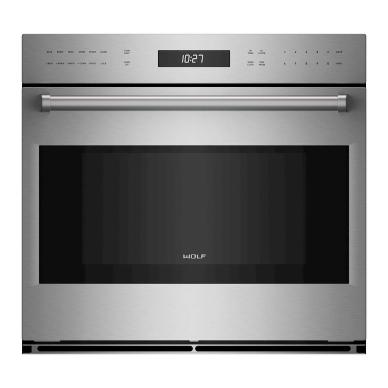
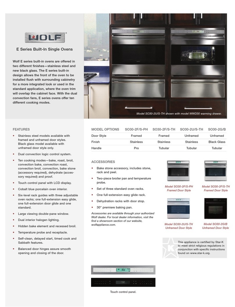
Wolf M Series Operating instructions

Troubleshooting
4-2
830805 - Rev. A - January, 2022
TROUBLESHOOTING
This section of the manual contains troubleshooting information which will help the Certified Service Technician trou-
bleshoot a Wolf M-Series Wall Oven. The table of contents below shows how the troubleshooting section is laid out.
NOTE: Not all components can be tested. In those instances the component most likely to cause the fault is
replaced. When problems reoccur a deeper look into the root cause is necessary. External factors may also be the
cause when faults reoccur.
Glossary
GUI Graphic User Interface - 7” display.
UIM User Interface Module – used interchangeably with UIP and Control Panel.
UIP User Interface Panel – electronics board behind control panel. Contains the main processor board.
PCM Power Control Module - relay board
HVM High Voltage Microprocessor on the relay board
LVM Low Voltage Microprocessor on the relay board
RTD Resistance Temperature Detector - oven temperature sensor
TCO Thermal Cut Out – A mechanical temperature limiting device
DLB Double Line Break – Safety relay system that disconnects both sides of an element
MDL Motorized Door Lock
EOC End of Cycle
TOD Time of Day
POST Power On Self Test - test performed by the UIP when power is supplied/returned to the relay board.
M Series Wall Oven (SWS #22605000)

Troubleshooting
4-3
830805 - Rev. A - January, 2022
Diagnostics
Entering Diagnostics (See Figure 4-1A and 4-1B)
1. From Idle mode touch any place on the Graphic
User Interface (GUI) and the main menu will
appear.
2. Touch SETTINGS.
(Continued)
Figure 4-1A Transitional Main Menu
Figure 4-1B Professional Main Menu
M Series Wall Oven (SWS #22605000)

Troubleshooting
4-4
830805 - Rev. A - January, 2022
Figure 4-3A Transitional About
Figure 4-2B Professional Settings Menu
Entering Diagnostics
1. The SETTINGS menu will be displayed (See
Figure 4-2A and 4-2B).
2. Use the pad of your finger to scroll the options until
ABOUT is centered on the display (See Figure 4-
3A an 4-3B).
(Continued)
Figure 4-2A Transitional Settings Menu
Figure 4-3B Professional About
M Series Wall Oven (SWS #22607000)

Troubleshooting
4-5
830805 - Rev. A - January, 2022
Entering Diagnostics
1. Touch ABOUT and the unit information screen will
open (See Figure 4-4A and 4-4B).
2. Touch and hold Ok for 10 full seconds and the gen-
eral diagnostics screen will open (See Figure 4-5A
and 4-5B).
General Diagnostics Screen
The general diagnostic screen has tabs across the top.
General, Faults, Statistics, Control, Knobs
(Professional only), and Exit.
There are two selections on the general diagnostics
screen. Start Self Test, and Reposition Screen.
Figure 4-4A Transitional Unit Information
Figure 4-4B Professional Unit Information
Figure 4-5A Transitional General Screen
Figure 4-5B Professional General Screen
M Series Wall Oven (SWS #22607000)

Troubleshooting
4-6
830805 - Rev. A - January, 2022
Figure 4-7 Self Test In Progress
Figure 4-8 Self Test Complete - No Faults
Figure 4-6 Reposition Screen
Reposition Screen
From the general diagnostics screen touch Reposition
Screen. A grid will appear on the GUI (See Figure 4-6).
1. Move the pad of your finger along the grid to
reposition the display.
2. Touch Set to exit reposition screen and save any
changes.
Self Test
Self test checks relays, triacs, and double line break
relays (DLB) on the relay board. Self Test takes about
two and half minutes on a double oven. Self Test uses
a progress bar to show progress and will report findings
after completion (See Figure 4-7).
1. Close the oven door(s).
2. Touch Self Test.
3. If no faults are found touch OK. Returns to general
diagnostic screen (See Figure 4-8).
4. If faults are found touch OK, and return to the gen-
eral diagnostics screen then touch Faults tab (See
Figure 4-9).
Figure 4-9 Self Test Complete - Faults Found
M Series Wall Oven (SWS #22607000)

Troubleshooting
4-7
830805 - Rev. A - January, 2022
Faults Tab
Fault codes are a four-digit numerical code that indicates the type, scope and specific component exhibiting the
fault.
First Digit: Fault Code
Indicates main type of fault and/or suspected faulty component. Faults will be grouped according to type of fault,
and suspected faulty component
0-2: Relay board related faults
3-4: External component or wiring faults
5: Temperature related faults
6: UIP board related faults
7: Knob encoder faults
8: Display faults
9. Touch Sensor faults
Second Digit: Component/Sub-Code
Identifies a particular output, element or a particular fault within a fault code group.
Third Digit: Priority
Possible priorities are 1, 2, or 3.
Priority 1: Safety related or of such catastrophic scope that the control is considered inoperable. Continuously
displayed to the end user, indicating a service call is necessary. No user functions will be allowed and any active
functions will be cancelled upon generation of the fault. The fault can be cleared, but will re-generate if the fault
still exists.
Priority 2: Displayed to the user only during an active cooking/clean mode or upon attempt to enter a
cooking/clean mode. Likely to limit the proper functionality of the system. Faults can be cancelled and will not be
displayed again until an attempt to start a mode that is directly related to the fault. Any active function will be can-
celled upon generation of the priority 2 fault in that cavity. Faults with system scope will apply to all cavities.
Priority 3: May cause some possible or conditionally impaired functionality. Faults, although logged internally, will
never be displayed to the end user.
Fourth Digit: Scope
Parts of the control system affected by the fault.
0: System Scope
1: Upper cavity
2: Lower cavity
NOTES:
It is not possible to test some faults. In those instances the repair is to replace the component.•
Ohming a circuit must be done with power cycled off, and the wire removed from the terminal.•
When testing voltage at a circuit the test should be set up with the power off - confirming that there are no wires•
or terminals in danger of shorting, then the circuit energized.
M Series Wall Oven (SWS #22607000)

Troubleshooting
4-8
830805 - Rev. A - January, 2022
Logging Faults
Up to 20 faults can be logged and viewed on the Faults tab. Faults can be cleared manually or from self-correcting.
If multiple instances of the same fault are detected the time stamp of the fault will updated to show the last occur-
rence.
Example of Faults Tab
The Faults tab lists the fault code under Code, the specific fault under Fault Name, and at what time it occurred
under Odometer. The bottom of Faults tab also provides the number of faults, the amount of time the unit has been
in operation, and the Clear Faults button to clear the fault codes. (See Figure 4-10).
Using the Fault Code Chart
The Fault Code Chart lists the faults by fault number. Then Priority. The next column is the suggested test proce-
dure for checking the fault. The last column is the action required.
Figure 4-10 Fault Tab Screen
M Series Wall Oven (SWS #22607000)

Troubleshooting
4-9
830805 - Rev. A - January, 2022
0021
0022
0121
0122
0221
0222
0321
0322
0421
0422
0521
0522
0630
0731
0732
0821
0822
2
2
2
2
2
2
2
2
2
2
2
2
3
3
3
2
2
Bake element relay shorted
Upper right convection element
relay shorted
Lower right convection element
relay shorted
Upper bake element DLB shorted
Lower bake element DLB shorted
Upper broil element relay shorted
Lower broil element relay shorted
Upper left convection element relay
shorted
Lower left convection element relay
shorted
Upper broil element DLB shorted
Lower broil element DLB shorted
Auxiliary DLB shorted
Upper oven light triac shorted
Lower oven light triac shorted
Upper MDL relay shorted
Lower MDL relay shorted
Ohm P1-1 to P1-4.
Ohm P5-1 to P5-4.
Ohm P1-6 to P1-4.
Ohm P5-6 to P5-4.
P2 - Dual DLB relay. Unable
to test.
P6 - Dual DLB relay. Unable
to test.
Ohm P3-4 to P3-1.
Ohm P7-4 to P7-1.
Ohm P3-4 to P3-6.
Ohm P7-4 to P7-6.
P4 - Dual DLB relay. Unable
to test.
P8 - Dual DLB relay. Unable
to test.
Ohm J5-8 to J5-9.
Back pin J5-2 and test for
voltage to ground - lights off.
Back pin J6-2 and test for
voltage to ground - lights off.
Ohm J5-3 to J5-1.
Ohm J6-4 to J6-1.
If continuity P1-1 to P1-4,
replace the relay board.
If continuity P5-1 to P5-4
replace relay board.
If continuity P1-6 to P1-4
replace relay board.
If continuity P5-6 to P5-4
replace relay board.
See Procedure A.
NOTE: Redundant DLB -
can't test individually.
See Procedure A.
NOTE: Redundant DLB -
can't test individually.
If continuity P3-4 to P3-1
replace relay board.
If continuity P7-4 to P7-1
replace relay board.
If continuity P3-4 to P3-6
replace relay board.
If continuity P7-4 to P7-6
replace relay board.
See Procedure A.
NOTE: Redundant DLB -
can't test individually
See Procedure A.
NOTE: Redundant DLB -
can't test individually.
If continuity replace the relay
board.
See Procedure D.
See Procedure D.
If continuity replace the relay
board.
If continuity replace the relay
board.
Relay Board Related Faults
Fault Priority Fault Message Test Action
M Series Wall Oven (SWS #22607000)

Troubleshooting
4-10
830805 - Rev. A - January, 2022
0931
0932
0A31
0A32
0B31
0B32
1021
1022
1121
1122
1231
1232
1321
1322
3
3
3
3
3
3
2
2
2
2
3
3
2
2
Upper right convection fan triac
shorted
Lower right convection fan triac
shorted
Upper left convection fan triac
shorted
Lower left convection fan triac
shorted
Upper cooling fan triac shorted
Lower cooling fan triac shorted
Upper bake element relay open
Lower bake element relay open
Upper right convection element
relay open
Lower right convection element
relay open
Upper bake element DLB open
Lower bake element DLB open
Upper broil element relay open
Lower broil element relay open
Back pin J5-4 and test for
voltage to ground with con-
vection fan off.
Back pin J6-5 and test for
voltage to ground with con-
vection fan off.
Back pin J5-5 and test for
voltage to ground with con-
vection fan off.
Back pin J6-6 and test for
voltage to ground with con-
vection fan off.
Back pin J5-6 and test for
voltage to ground with cooling
fan off.
Back pin J6-7 and test for
voltage to ground with cooling
fan off.
Back pin P1-1 and test for
voltage to ground with bake
element energized.
Back pin P5-1 and test for
voltage to ground with bake
element energized.
Back pin P1-6 and test for
voltage to ground with right
convection element ener-
gized.
Back pin P5-6 and test for
voltage to ground with right
convection element ener-
gized.
P2 - Dual DLB relay. Unable
to test.
P5 - Dual DLB relay. Unable
to test.
Back pin P3-1 and test for
voltage to ground with broil
element energized.
Back pin P7-1 and test for
voltage to ground with broil
element energized.
See Procedure D.
See Procedure D.
See Procedure D.
See Procedure D.
See Procedure D.
See Procedure D.
If no voltage, replace the
relay board.
If no voltage, replace the
relay board.
If no voltage, replace the
relay board.
If no voltage, replace the
relay board.
See Procedure A.
NOTE: Redundant DLB -
can't test individually.
See Procedure A.
NOTE: Redundant DLB -
can't test individually.
If no voltage, replace the
relay board.
If no voltage, replace the
relay board.
Fault Priority Fault Message Test Action
M Series Wall Oven (SWS #22607000)

Troubleshooting
4-11
830805 - Rev. A - January, 2022
1421
1422
1531
1532
1620
1731
1732
1831
1832
1931
1932
1A31
1A32
2
2
3
3
2
3
3
3
3
3
3
3
3
Upper left convection element relay
open.
Lower left convection element relay
open.
Upper broil element DLB open
Lower broil element DLB open
Auxiliary DLB open
Upper oven light triac open
Lower oven light triac open
Upper MDL relay open
Lower MDL relay open
Upper right convection fan triac
open
Lower right convection fan triac
open
Upper left convection fan triac
open
Lower left convection fan triac
open
Back pin P3-6 and test for
voltage to ground with left
convection element ener-
gized.
Back pin P7-6 and test for
voltage to ground with left
convection element ener-
gized.
P4 - Dual DLB relay. Unable
to test.
P8 - Dual DLB relay. Unable
to test.
With power to unit, and MDL,
lights, convection fans, and
cooling fan off.
1. Back pin and check volt-
age J5-8 to J5-9.
2. Activate lights.
Back pin J5-2 and test for
voltage to ground with lights
energized.
Back pin J6-2 and test for
voltage to ground with lights
energized.
Back pin J5-3 and test for
voltage to ground with MDL
energized.
Back pin J6-4 and test for
voltage to ground with MDL
energized.
Back pin J5-4 and test for
voltage to ground with con-
vection fan energized.
Back pin J6-5 and test for
voltage to ground with con-
vection fan energized.
Back pin J5-5 and test for
voltage to ground with con-
vection fan energized.
Back pin J6-6 and test for
voltage to ground with con-
vection fan energized.
If no voltage, replace the
relay board.
If no voltage, replace the
relay board.
See Procedure A.
NOTE: Redundant DLB -
can't test individually.
See Procedure A.
NOTE: Redundant DLB -
can't test individually.
Voltage should change from
120 VAC to 0 VAC when
lights are activated. If no
change replace relay board.
See Procedure E.
See Procedure E.
If no voltage replace relay
board.
If no voltage replace relay
board.
See Procedure E.
See Procedure E.
See Procedure E.
See Procedure E.
Fault Priority Fault Message Test Action
M Series Wall Oven (SWS #22607000)

Troubleshooting
4-12
830805 - Rev. A - January, 2022
1B21
1B22
1C21
1D21
1E22
1F22
2030
2130
2230
2330
2420
2521
2522
2631
2632
2720
2
2
2
2
2
2
3
3
3
3
2
2
2
3
3
2
Upper cooling fan triac shorted
Lower cooling fan triac shorted
Both upper bake element DLB's
open
Both upper broil element DLB's
open
Both lower bake element DLB's
open
Both lower broil element DLB's
open
Relay board ambient thermistor cir-
cuit fault
Relay board voltage calibration
failed
Relay board RTD circuit calibration
failed
Relay board relay circuit calibration
failed
Relay board RTD circuit fault
Relay board upper MDL input cir-
cuit fault
Relay board lower MDL input circuit
fault
Relay board upper door switch cir-
cuit fault
Relay board lower door switch cir-
cuit fault
Output drive watchdog fault
Back pin J5-6 and test for
voltage to ground with cooling
fan off.
Back pin J6-7 and test for
voltage to ground with cooling
fan off.
Back pin P2-6 and test for
voltage to ground with bake
element energized.
Back pin P4-6 and test for
voltage to ground with broil
element energized.
Back pin P6-6 and test for
voltage to ground with bake
element energized.
Back pin P8-6 and test for
voltage to ground with broil
element energized.
Relay board ambient thermis-
tor circuit fault. Not able to
test
Relay board voltage not cali-
brated. Not able to test.
Unable to test relay board
RTD circuit.
Relay board relays not cali-
brated. Not able to test.
Relay board RTD internal cir-
cuit fault. Not able to test.
Relay board MDL input circuit.
Not able to test.
Relay board MDL input circuit.
Not able to test.
Relay board internal door
switch circuit fault. Not able
to test.
Relay board internal door
switch circuit fault. Not able
to test.
Element or MDL watchdog
fault. Not able to test.
See Procedure D.
See Procedure D.
If voltage is not between 115
VAC ±25 VAC replace relay
board.
If voltage is not between 115
VAC ±25 VAC replace relay
board.
If voltage is not between 115
VAC ±25 VAC replace relay
board.
If voltage is not between 115
VAC ±25 VAC replace relay
board.
See Procedure A.
See Procedure A.
See Procedure A.
See Procedure A.
See Procedure A.
See Procedure A.
See Procedure A.
See Procedure A.
See Procedure A.
See Procedure A.
Fault Priority Fault Message Test Action
M Series Wall Oven (SWS #22607000)

Troubleshooting
4-13
830805 - Rev. A - January, 2022
2820
2930
2A30
2B30
2C20
2D30
2E30
2
3
3
3
2
3
3
Relay board MDL relay circuit fault
Relay board conversion circuit fault
Microprocessor comm fault
Microprocessor monitor circuit fault
Relay board network fault
Relay board 13.5 VDC fault
Relay board 12 VDC fault
Relay board internal MDL
relay circuit fault. Not able to
test.
Relay board internal conver-
sion circuit fault. Not able to
test.
Not able to test.
Not able to test.
Try removing any external
RS485 connections.
Reseat RS485 comm cable
Relay board 13.5 VDC fault.
Not able to test.
12 VDC for external RS485
connection.
See Procedure A.
See Procedure A.
See Procedure A.
See Procedure A.
Replace UIP.
See Procedure A.
Clear fault unless Smart Grid
system is being used. If
Smart Grid being used -
replace relay board.
Fault Priority Fault Message Test Action
3031
3032
3121
3122
3221
3222
3
3
2
2
2
2
Upper temperature probe shorted
Lower temperature Probe shorted
Upper RTD shorted
Lower RTD shorted
Upper RTD open
Lower RTD open
See Procedure B.
See Procedure B.
See Procedure C.
See Procedure C.
See Procedure C.
See Procedure C.
1. Try to clear fault.
2. If no short found replace
relay board.
1. Try to clear fault.
2. If no short found replace
relay board.
1. Try to clear fault.
2. If no short found replace
relay board.
1. Try to clear fault.
2. If no short found replace
relay board.
1. Try to clear fault.
2. If no open found replace
relay board.
1. Try to clear fault.
2. If no open found replace
relay board.
Fault Priority Fault Message Test Action
External Component Or Wiring Faults
M Series Wall Oven (SWS #22607000)

Troubleshooting
4-14
830805 - Rev. A - January, 2022
3311
3312
3421
3422
3521
3522
3621
3622
1
1
2
2
2
2
2
2
Upper TCO open
Lower TCO open
Upper MDL timeout
Lower MDL timeout
Upper door open/unlocked in clean
Lower door open/unlocked in clean
Upper door locked, not in clean
Lower door locked, not in clean
See Procedure I.
See Procedure I.
1. Ensure MDL is moving.
2. Check J2-3 to J2-1 has
continuity when unlocked.
3. Check J2-2 to J2-1 has
continuity when locked.
1. Ensure MDL is moving.
2. Check J3-4 to J3-2 has
continuity when unlocked.
3. Check J3-3 to J3-2 has
continuity when locked.
1. Ensure MDL is moving.
2. Check J2-4 to J2-5 has
continuity when door
closed.
3. Check J2-2 to J2-1 has
continuity when locked.
1. Ensure MDL is moving.
2. Check J3-5 to J3-6 has
continuity when door
closed.
3. Check J3-3 to J3-2 has
continuity when locked.
1. Check if MDL is out of
position.
2. Check for continuity J2-2 to
J2-1 with door unlocked.
1. Check if MDL is out of
position.
2. Check for continuity J3-3 to
J3-2 with door unlocked.
1. Have environmental issue
corrected.
2. Repair wiring or insulation.
3. Replace TCO.
1. Have environmental issue
corrected.
2. Repair wiring or insulation.
3. Replace TCO.
If fault 0821, 1831, 2521, or
2820 replace relay board.
If lock or unlocked Micro
Switch is not closing replace
MDL.
NOTE: UIP will make 3
attempts of 45 second each
to sense MDL position before
it times out. If it times out the
breaker must be reset.
If fault 0822, 1832, 2522, or
2820 replace relay board. If
lock or unlocked Micro Switch
is not closing replace MDL.
NOTE: UIP will make 3
attempts of 45 second each
to sense MDL position before
it times out. If it times out the
breaker must be reset.
If fault 0821, 1831, 2521, or
2820 replace relay board.
If no continuity replace MDL.
NOTE: Door switch uses
magnet. Check if being
sensed.
If fault 0822, 1832, 2522, or
2820 replace relay board.
If no continuity replace MDL.
NOTE: Door switch uses
magnet. Check if in place.
If continuity between J2-2
and J2-1 with door unlocked
replace MDL.
If continuity between J3-3
and J3-2 with door unlocked
replace MDL.
Fault Priority Fault Message Test Action
M Series Wall Oven (SWS #22607000)

Troubleshooting
4-15
830805 - Rev. A - January, 2022
3721
3722
3821
3822
3921
3922
3A20
3B20
3C20
3D20
4031
4032
4131
2
2
2
2
2
2
2
2
2
2
3
3
3
Upper MDL invalid switch position
Lower MDL invalid switch position
Upper bake bank wiring fault
Lower bake bank wiring fault
Upper broil bank wiring fault
Lower broil bank wiring fault
Auxiliary bank wiring fault
Low input voltage
High input voltage
Input voltage frequency fault
Upper bake element not detected
Lower bake element not detected
Upper right convection element not
detected
See Procedure F.
See Procedure F.
Bake element not energized.
1. Measure voltage from P1-4
to ground.
2. Measure voltage from P2-4
to ground.
Bake element not energized.
1. Measure voltage from P1-4
to ground.
2. Measure voltage from P2-4
to ground.
Broil element not energized.
1. Measure voltage from P3-4
to ground.
2. Measure voltage from P4-4
to ground.
Broil element not energized.
1. Measure voltage from P7-4
to ground.
2. Measure voltage from P8-4
to ground.
Lights, MDL, convection fans,
and cooling fan not energized.
1. Measure voltage from P5-1
to ground.
2. Measure voltage from P5-9
to ground.
3. On double ovens measure
voltage J6-1 to ground.
J7-1 to J7-5 (L1 to L2) voltage
below 177 VAC.
J7-1 to J7-5 (L1 to L2) voltage
above 265 VAC.
Input voltage frequency not
between 47 Hz and 63 Hz.
Not able to test.
Ohm wire from P1-1 to wire
from P2-6.
Ohm wire from P5-1 to wire
from P6-6.
Ohm wire from P1-6 to wire
from P2-6.
Repair/replace wiring or
replace MDL.
Repair/replace wiring or
replace MDL.
No 120 volts from either test:
1. Verify L1 and L2 supply
are good.
2. Repair wiring.
3. Replace relay board.
No 120 volts from either test:
1. Verify L1 and L2 supply
are good.
2. Repair wiring.
3. Replace relay board.
No 120 volts from either test:
1. Verify L1 and L2 supply
are good.
2. Repair wiring.
3. Replace relay board.
No 120 volts from either test:
1. Verify L1 and L2 supply
are good.
2. Repair wiring.
3. Replace relay board.
No 120 volts from any test:
1. Verify L1 and L2 supply
are good.
2. Repair wiring.
3. Replace relay board.
Check supply voltage, termi-
nal block and wiring.
Check supply voltage, termi-
nal block or wiring issue.
Supply voltage issue.
If not 15.4 to 17 ohms
replace bake element.
If not 15.4 to 17 ohms
replace bake element.
If not 22 to 25.6 ohms
replace convection element.
Fault Priority Fault Message Test Action
M Series Wall Oven (SWS #22607000)

Troubleshooting
4-16
830805 - Rev. A - January, 2022
4132
4231
4232
4331
4332
4421
4422
4531
4532
4631
4632
4731
4732
4831
4832
3
3
3
3
3
2
2
3
3
3
3
3
3
3
3
Lower right convection element not
detected
Upper broil element not detected
Lower broil element not detected
Upper left convection element not
detected
Lower left convect element not
detected
Upper cooling fan not detected
Lower cooling fan not detected
Upper right convection fan not
detected
Lower right convection fan not
detected
Upper left convection fan not
detected
Lower left convection fan not
detected
Upper oven lights not detected
Lower oven lights not detected
Upper MDL not detected
Lower MDL not detected
Ohm wire from P5-6 to wire
from P6-6.
Ohm wire from P3-1 to wire
from P4-6.
Ohm wire from P7-1 to wire
from P8-6.
Ohm wire from P3-6 to wire
from P4-6.
Ohm wire from P7-6 to wire
from P8-6.
Remove connector - ohm
from wire J5-6 to wire from
J5-8.
Remove connector - ohm
from wire J6-7 to wire from
J5-8.
Remove connector - ohm
from wire J5-4 to wire from
J5-8.
Remove connector - ohm
from wire J6-5 to wire from
J5-8.
Remove connector - ohm
from wire J5-5 to wire from
J5-8.
Remove connector - ohm
from wire J6-6 to wire from
J5-8.
Remove connector - ohm
from wire J5-2 to wire from
J5-8.
Remove connector - ohm
from wire J6-2 to wire from
J5-8.
Remove connector - ohm
from wire J5-3 to wire from
J5-8.
Remove connector - ohm
from wire J6-4 to wire from
J5-8.
If not 22 to 25.6 ohms
replace convection element.
If not 14.8 to 16.4 ohms
replace broil element.
If not 14.8 to 16.4 ohms
replace broil element.
If not 22 to 25.6 ohms
replace convection element.
If not 22 to 25.6 ohms
replace convection element.
If not 45 ohms ± 20% replace
cooling fan.
If not 45 ohms ± 20% replace
cooling fan.
If not 90 ohms ± 20% replace
convection fan.
If not 90 ohms ± 20% replace
convection fan.
If not 90 ohms ± 20% replace
convection fan.
If not 90 ohms ± 20% replace
convection fan.
1. Check all three bulbs.
2. No continuity check wiring
and connector.
1. Check all three bulbs.
2. No continuity check wiring
and connector.
Not 12k ohms ± 20% replace
MDL.
Not 12k ohms ± 20% replace
MDL.
Fault Priority Fault Message Test Action
M Series Wall Oven (SWS #22607000)

Troubleshooting
4-17
830805 - Rev. A - January, 2022
Fault Priority Fault Message Test Action
4910
4A10
5021
5022
5121
5122
5220
5320
5431
5432
1
1
2
2
2
2
2
2
3
3
Upper cooling fan HES stall detect-
ed
Lower cooling fan HES stal detect-
ed
Upper cavity over temp during
clean
Lower cavity over temp during
clean
Upper cavity over temp during non-
clean
Lower cavity over temp during non-
clean
Relay board ambient over temper-
ature
UIP ambient over temperature
Low rate-of-rise, upper self-clean
Low rate-of-rise, lower self-clean
Cooling fan rotation is not reg-
istering/not rotating.
Cooling fan rotation is not reg-
istering/not rotating.
Over 950° F. Test oven tem-
perature per test procedure G.
Over 950° F. Test oven tem-
perature per test procedure G.
Over 600° F. Test oven tem-
perature per test procedure G.
Over 600° F. Test oven tem-
perature per test procedure G.
Above 185° F in relay board
area.
Above 185° F in UIP area.
Temperature issue. See
Procedure H.
Temperature issue. See
Procedure H.
1. Verify HES harness seated.
2. Verify correct relay board.
3. Replace cooling fan.
1. Verify HES harness seated.
2. Verify correct relay board.
3. Replace cooling fan.
1. Flash UIP board.
2. Replace UIP board.
3. Replace relay board.
1. Flash UIP board.
2. Replace UIP board.
3. Replace relay board.
1. Flash UIP board.
2. Replace UIP board.
3. Replace relay board.
1. Flash UIP board.
2. Replace UIP board.
3. Replace relay board.
1. Measure and compare
temperature in diagnostics
(Control tab) to thermo-
couple. If not reading cor-
rectly replace relay board.
2. Check for obstructions in
air channel.
3. Check cooling fan(s).
1. Check for obstructions in
air channel.
2. Check cooling fan(s).
3. Measure temperature at
UIP. If not getting that hot
replace UIP.
1. Report voltage issue.
2. Bad element or wiring
repair or replace.
3. Replace UIP.
1. Report voltage issue.
2. Bad element or wiring
repair or replace.
3. Replace UIP.
Temperature Related Faults
M Series Wall Oven (SWS #22607000)

Troubleshooting
4-18
830805 - Rev. A - January, 2022
UIP Board Related Faults
6020
6110
6210
6320
6410
6510
6610
6630
6730
6810
6830
6910
6A10
6A30
6B30
6C10
6C30
6D10
2
1
1
2
1
1
1
3
3
1
3
1
1
3
3
1
3
1
UIM RS485 network fault
General Program Fault
UIM configuration data fault
UIM invalid configuration data
Inter-module communication fault
Inter-Module COM fault - Monitor
Display position not calibrated
UIM ambient thermistor circuit fault
UIM flash memory fault
UIM ambient thermistor circuit fault
UIM RAM fault
UIM RAM fault
Ethernet communication fault
USB communication fault
Touch sensor communications fault
USB communication fault
Touchpad communications fault
UIM network fault between relay
board and/or UIP or RS485
user’s connection.
UIP program crash. Not able to
test.
UIM configuration fault. Not able
to test.
UIM configuration data fault.
Not able to test.
Unable to test.
Unable to test.
Unable to test.
Display position not calibrated.
UIM ambient thermistor circuit
fault. Not able to test
UIM flash memory fault. Not
able to test.
Over temperature in UIM area.
UIM RAM memory fault. Not
able to test.
UIM RAM memory fault
Not currently in Use
USB terminal used currently
only for Software update.
Reseat cable. Reset Unit.
Unable to test.
Reseat the cable.
1. Check RS485 cable and
connectors.
2. If good, replace UIM.
1. Flash UIP software.
2. See Procedure A.
1. Flash UIM software.
2. See Procedure A.
1. Flash UIM software.
2. See Procedure A.
See Procedure A.
See Procedure A.
See Procedure A.
Calibrate Display in diagnos-
tics.
1. Flash UIM software.
2. See Procedure A.
1. Flash UIM software.
2. See Procedure A.
1. Check for obstruction in air
channel
2. Check cooling fan(s)
3. Check temperature at UIP
- if not overheated replace
UIM.
1. Flash UIM software.
2. See Procedure A.
1. Flash UIM software.
2. See Procedure A.
NA
Replace UIP.
If fault does not clear replace
UIP.
See Procedure A.
Replace the control panel.
Fault Priority Fault Message Test Action
v
M Series Wall Oven (SWS #22607000)

Troubleshooting
4-19
830805 - Rev. A - January, 2022
7021
7022
7121
7122
2
2
2
2
Upper mode selector knob input
fault
Lower mode selector knob input
fault
Upper temperature selector knob
input fault
Lower temperature selector knob
input fault
Reseat cable.
Reseat cable.
Reseat cable.
Reseat cable.
Replace mode select
encoder.
Replace mode select
encoder.
Replace adjust encoder.
Fault Priority Fault Message Test Action
8010
8110
1
1
Display back light fault
Display fault
Reseat the cable.
Reseat the cable.
Replace the display.
Fault Priority Fault Message Test Action
Knob Encoder Faults - Professional Knobs
Touch Sensor Faults
Display Faults100
9010
9020
9120
1
2
2
Touchpad sensor fault
Touch sensor fault
Touch sensor fault
Reseat the cable.
Reseat the cable.
Reseat the cable.
Replace the control panel.
Fault Priority Fault Message Test Action
M Series Wall Oven (SWS #22607000)

Fault Code Test Procedures
Procedure A: Untestable Fault
1. Clear the fault through the Faults tab by pressing Clear Faults.
2. Cycle the power to the unit. Leave the power off at least five minutes.
3. Run Self Test again.
4. Test unit in mode it failed in.
If fault returns replace the relay board or the UIP depending on fault code.
Procedure B: Testing Probe Circuit
1. Ohm out Probe. Probe should ohm out at 62k ohms +/- 3k ohms at 68 degrees (See Figure 4-11).
2. If probe ohms out correctly, insert probe into jack.
a. Ohm out between J2-6 and J2-7 on single and upper ovens, and between J3-8 and J3-9 on lower ovens.
Resistance will be high if the circuit is open.
b. Ohm out J2-6 and J2-7 to ground for single and upper ovens and J3-8 and J3-9 to ground on lower
ovens. Resistance will be low if there is a short in the circuit.
3. Repair any loose or damaged connections.
4. If open or short appears to be in probe jack contact the Wolf Tech Line at 800.919.8324.
Procedure C: Shorted or open RTD
Upper RTD terminals are J2-9 and J2-10. Lower RTD
terminals are J3-10 and J3-11.
For a shorted RTD:
1. Ohm each terminal to ground. If resistance is
low there is a short.
2. Ohm terminal to terminal. RTD should ohm out
at 1076 ohms +/- 5 ohms at 68 degrees.
3. Isolate location of short in circuit.
4. If short is in RTD contact Wolf Tech Line at
800.919.8324.
For an open RTD:
1. Ohm terminal to terminal. RTD should ohm out
at 1076 ohms +/- 5 ohms at 68 degrees.
2. Isolate location of open in circuit.
3. If open is in RTD contact Wolf Tech Line at
800.919.8324.
Procedure D: Testing a Triac for a short
A short in a Triac means that it is passing full voltage
when it should not be.
NOTE: It is normal for a Triac to have voltage bleed
through of 40 to 80 VAC.
1. Measure voltage from component L1 inlet to
ground when component is not energized. If
voltage is 115 VAC ± 25 VAC the Triac is pass-
ing full voltage and is shorted.
2. If Triac is shorted replace the relay board.
Figure 4-11 Ohming Out Probe
Measure Between Point A and B
AB
Troubleshooting
4-20
830805 - Rev. A - January, 2022
M Series Wall Oven (SWS #22607000)

Troubleshooting
4-21
830805 - Rev. A - January, 2022
Description
Fault condition
Transition State
Door Unlocked
Door Locked
Procedure E: Testing a Triac for Open
An open in a Triac means that it will not pass full voltage when energized.
NOTE: It is normal for a Triac to have voltage bleed through of 40 to 80 VAC. It is possible to get bleed through if
the Triac has failed open.
1. Measure voltage from component L1 inlet to ground when component is energized. If voltage is not 115
VAC ± 25 VAC the Triac is not passing full voltage and is open.
2. If Triac is open replace the relay board.
Procedure F: MDL Invalid Switch Position
There are only four possible switch configurations. Compare switch positions to the chart below. Determine fault
and replace MDL or correct wiring.
Procedure G: Oven Temperature to High
If the oven is reading over temperature it is caused by a relay not releasing correctly, RTD circuitry issue, or program
issue. Perform the following tests:
1. Place a thermocouple or suitable thermometer in the center of the oven cavity.
2. Initiate the mode the oven failed in.
3. Monitor oven RTD to thermocouple temperature. Any temperature difference should remain consistant. An
increasing temperature difference is typically a software issue.
4. If oven does not appear to be cycling off properly confirm element relays are opening. One relay not opening
is typically a relay issue. Multiple relays not opening is usually a software issue.
5. On double ovens check both cavities. Both cavities being off is usually a software issue.
6. Flash UIP software.
7. Confirm RTD wiring and element wiring is in good condition and has no shorts.
8. If RTD contact Wolf Tech Line at 800.414.8324.
Procedure H: Low Rate of Temperature Rise in Self Clean
Low rate of rise in self clean can be from a voltage issue, element issue, software issue, or RTD wiring issue.
Criteria for temperature rise is: 60 minutes for 700° F at 240 VAC 60 Hz; 120 Minutes at 230 VAC 50 Hz; and 150
minutes at 208 VAC 50/60 Hz.
1. Ohm out all elements.
2. Check each element L1 and L2 leg to ground.
3. Place a thermocouple or suitable thermometer in the center of the oven cavity.
4. Initiate self clean.
5. Monitor oven RTD to thermocouple temperature and confirm an issue of reaching temperature in correct time.
6. Check voltage L1 to L2, L1 to ground, and L2 to ground while oven is heating.
7. Flash UIP software.
8. If RTD contact Wolf Tech Line at 800.414.8324.
Unlatched
Closed
Open
Closed
Open
Latched
Closed
Open
Open
Closed
M Series Wall Oven (SWS #22607000)
Other manuals for M Series
13
Table of contents
Other Wolf Oven manuals

Wolf
Wolf Convection Steam Oven User manual

Wolf
Wolf CONVECTION STEAM OVENS User manual

Wolf
Wolf L Series SO30F User manual

Wolf
Wolf L Series User manual

Wolf
Wolf E Series Operating manual

Wolf
Wolf e Series User manual

Wolf
Wolf CSO30PE/S/PH User manual

Wolf
Wolf DO30U/P Owner's manual

Wolf
Wolf DO30F/S L Series User manual

Wolf
Wolf Speed SPO30S User manual