WPG MRTALPCH611DC3 User manual

INTENDED FOR USE BY SKILLED
PROFESSIONALS • READ AND
UNDERSTAND BEFORE OPERATING
OPERATING
INSTRUCTIONS
CHANNEL-
STYLE, LOW-PROFILE
MANUAL ROTATOR /
TILTER, DC-VOLTAGE, WITH
INTELLI-GRIP® TECHNOLOGY
Available with REMOTE CONTROL SYSTEM
Model numbers: MRTALPCH611DC3,
MRTALPCH610LDC3O, MRTALPCH610CDC3O
KEEP FOR FUTURE REFERENCE

Rev 1.0/12-19 MRTALPCH6-DC3(RC): #351251
SPECIFICATIONS .....................................................................................3
SAFETY...................................................................................................5
OPERATING FEATURES............................................................................6
ASSEMBLY..............................................................................................7
TOCHANGE THE PAD FRAME CONFIGURATION ..................................................9
Installing/Removing Pad Frame Extensions ......................................................................10
Routing Vacuum Hoses .....................................................................................................11
Connecting/Disconnecting Vacuum Hoses .......................................................................12
INTENDED USE .....................................................................................13
LOAD CHARACTERISTICS...............................................................................13
OPERATING ENVIRONMENT ..........................................................................14
DISPOSAL OF THE LIFTER .............................................................................14
OPERATION..........................................................................................15
BEFORE USING THE LIFTER...........................................................................15
Taking Safety Precautions .................................................................................................15
Selecting a Screen Language.............................................................................................15
Performing Inspections and Tests .....................................................................................16
Checking the 12-Volt Battery ............................................................................................16
Preparing to Use the Remote Control System ..................................................................17
TOATTACH THE PADS TO ALOAD ..................................................................18
Positioning the Lifter on the Load.....................................................................................18
Powering up the Lifter ......................................................................................................19
Sealing the Pads on the Load............................................................................................19
Reading the Vacuum Gauges ............................................................................................20
TOLIFT AND MOVE THE LOAD......................................................................21
About the Tilt Linkage.......................................................................................................21
Interpreting the Lift Light..................................................................................................22
Watching Vacuum Indicators ............................................................................................22
Controlling the Lifter and Load .........................................................................................23
In Case of a Power Failure.................................................................................................23
TOROTATE THE LOAD .................................................................................24
TOTILT THE LOAD ......................................................................................25
TORELEASE THE PADS FROM THE LOAD .........................................................27
TABLE OF CONTENTS

MRTALPCH6-DC3(RC): #35125 Rev 1.0/12-192
AFTER USING THE LIFTER.............................................................................28
Storing the Lifter ...............................................................................................................28
INSPECTIONS AND TESTS......................................................................30
INSPECTION SCHEDULE ................................................................................30
TESTING ...................................................................................................31
Lifter/Load Compatibility Test...........................................................................................31
Operational Tests ..............................................................................................................32
Vacuum Test......................................................................................................................32
Rated Load Test.................................................................................................................33
Remote Control System Test .............................................................................................33
MAINTENANCE ....................................................................................34
VACUUM PAD MAINTENANCE.......................................................................34
Pad-to-Load Friction Coefficient .......................................................................................34
Pad Inspection ..................................................................................................................34
Pad Cleaning .....................................................................................................................35
NOTIFICATION BUZZER BATTERY REPLACEMENT ...............................................35
12-VOLT BATTERY RECHARGE.......................................................................36
INTELLI-GRIP® DIAGNOSTIC CODES ...............................................................37
REPLACEMENT PARTS...........................................................................41
LIMITED WARRANTY ............................................................................42
TOOBTAIN REPAIRS OR WARRANTY SERVICE...................................................42
TABLE OF CONTENTS

Product
Description
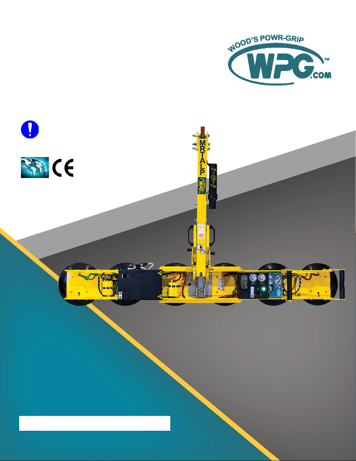
Designed for use with hoisting equipment, MRTALPCH6-DC3 lifters support loads using vacuum and
manipulate loads using manual 180° rotation and mechanically assisted, manual 90° tilt motions.
Model
Number MRTALPCH611LDC3 MRTALPCH610LDC3O MRTALPCH610CDC3O
Vacuum Pads
(6 each, standard rubber1
1...... Available with other rubber compounds for special purposes (see www.WPG.com).
)
11" [28 cm] nom. diameter,
lipped (Model G3370)
10" [25 cm] nom. diameter,
lipped (Model HV11)
10" [25 cm] nom. diameter, con-
cave (Model G0750)
Pad Spread ---------------------------- (to outer edges) ----------------------------
Maximum 79¼" x 12" [201 cm x 30 cm] 78¼" x 11" [199 cm x 28 cm] 77¼" x 10" [196 cm x 25 cm]
Minimum 53¾" x 12" [137 cm x 30 cm] 52¾" x 11" [134 cm x 28 cm] 51¾" x 10" [131 cm x 25 cm]
Maximum
Load Capacity2
2...... The Maximum Load Capacity is rated at a vacuum of 18 Hg [-60 kPa] on clean, smooth, nonporous flat surfaces with a friction coefficient of 1. Pad
compound, load rigidity, strength, surface conditions, overhang, angle, center of gravity and temperature can also affect the lifting capacity. A qualified
person should evaluate the effective lifting capacity for each use (see definition under “Rated Load Test” on page 33).
Per-Pad 184 lbs [83.5 kg] 150 lbs [68.5 kg] 150 lbs [68.5 kg]
Total with 4 Pads 700 lbs [320 kg] 600 lbs [270 kg] 600 lbs [270 kg]
Total with 6 Pads 1,100 lbs [500 kg] 900 lbs [410 kg] 900 lbs [410 kg]
Lifter
Weight 130 lbs [59 kg]
Power
System 12 volts DC, 4.5 amps
Battery
Capacity 7 amp-hours
Rotation
Capability Manual, 180°, with latching at each ¼ turn (when required)
Tilt
Capability
Manual, 90°, with automatic latching in upright position and four-bar tilt linkage that provides mechanical
advantage
Product
Options
Available with Remote Control System – FCC, CE and ICC certified.
See separate instructions about other options.
Operating
Elevation Up to 4,500' [1,370 m]
Operating
Temperatures 32° — 104° F [0° — 40° C]
Service
Life 20,000 lifting cycles, when used and maintained as intended3
3...... Vacuum pads, filter elements and other wear-out items are excluded.
Software
Version Intelli-Grip®7.6
ASME Standard
BTH-1 Design Category "B", Service Class "0" (see www.WPG.com for more information)
Rev 1.0/12-19 MRTALPCH6-DC3(RC): #351253
!!–CE–!! This symbol appears only when a CE Standard is different from other applicable standards. CE requirements are
mandatory in the European Union, but may be optional elsewhere.
SPECIFICATIONS

MRTALPCH6-DC3(RC): #35125 Rev 1.0/12-194
Note: A standard MRTALPCH611LDC3 is shown.
SPECIFICATIONS

Rev 1.0/12-19 MRTALPCH6-DC3(RC): #351255
SAFETY
Wear personal protective
equipment that is appropriate for
the load material. Follow trade
association guidelines.
Do not remove or obscure safety
labels.
Do not make any modifications to
the lifter (see “LIMITED
WARRANTY”).
Use the lifter only in an approved
“OPERATING ENVIRONMENT”(see
“INTENDED USE”).
Do not use a lifter that is damaged,
malfunctioning, or missing parts.
Do not use a lifter if the sealing
edge of any vacuum pad is cut or
otherwise damaged.
Do not use a lifter to lift cracked or
broken glass.
Do not exceed the Maximum
Load Capacity or lift loads the
lifter is not designed for (see
“INTENDED USE”).
Do not use a lifter if the
Maximum Load Capacity or
any safety label appears to be
missing or obscured.
Make sure the contact surfaces of
the load and vacuum pads are clean
before attaching the lifter (see
“MAINTENANCE”).
Position the vacuum pads correctly
on the load before lifting (see
“OPERATION: Positioning the Lifter
on the Load”).
Do not lift a load if any vacuum
indicator shows inadequate
vacuum.
Keep unauthorized personnel away
from the lifter, to avoid injury in
case of an unintended load release.
Do not touch the vacuum release
controls during a lift.
Do not allow people to ride on the
lifter or the load.
Do not lift a load higher than
necessary or leave suspended loads
unattended.
Do not position a loaded or
unloaded lifter over people.
Before servicing a powered lifter,
place the power control in the
inactive position and, when
possible, disconnect the power source.

MRTALPCH6-DC3(RC): #35125 Rev 1.0/12-196
Features shown here are underlined on their first appearance in each section following.
1 LIFT POINT 11 INTELLI-GRIP®CONTROL UNIT 15 BUZZER BATTERY HOLDER
2 LIFT BAR 11a “RELEASE” BUTTON 16 VACUUM RESERVE TANKS
3 INSTRUCTIONS CANISTER 11b “ATTACH” BUTTON 17 VACUUM PAD
4 ROTATION RELEASE LEVER 11c “FUNCTION” BUTTON 18 Window for BATTERY CHARGER
5 STROBE LIGHT 11d “POWER” BUTTON 19 Cover for VACUUM PUMP, BATTERY
6 VACUUM GAUGES 11e LCD SCREEN with BATTERY GAUGE and BATTERY CHARGER
7 VACUUM LIFT LIGHT 12 NOTIFICATION BUZZER 20 PAD FRAME
8 QUICK CONNECTOR 13 Windows for AIR FILTERS 21 TILT RELEASE LEVER
9 PAD FRAME EXTENSION 14 Cover for AIR FILTERS, CIRCUIT BOARD
10 CONTROL HANDLES and VACUUM SENSORS
Note: A standard MRTALPCH611LDC3 is shown. Although some of the following photos do not
show this specific lifter, they all illustrate how this kind of lifter functions.
OPERATING FEATURES

Rev 1.0/12-19 MRTALPCH6-DC3(RC): #351257
1) Remove all vacuum lifter restraints and save them with the shipping container for future
use.
2)
2A
If necessary, assemble the lift bar (item 1 in fig. 2A). Tighten
bolts (item 2 in fig. 2A) securely.
3) Adjust the lift point to optimize the lifter's hang angle:
3.1) Remove the retaining bolt (item 3 in fig. 2A) and loosen
the pivot bolt (item 4 if fig. 2A).
3.2) Move the lift point to the appropriate position.
3.3) Reinstall the retaining bolt and tighten both bolts
securely.
Note: Position the lift point to avoid contact with long
configurations of the pad frame during rotation.
4) Suspend the lifter from appropriate hoisting equipment:
4.1) Select a crane and/or hoist rated for the Maximum Load Capacity plus
the Lifter Weight.
Note: Any lifter use must comply with all statutory or regulatory standards for
hoisting equipment in your region.
4.2)
4A
4B
4C
Pull the tilt release
lever (fig. 4A) to
disengage the tilt
latch. Then raise the
lift bar (figs. 4B-C).
ASSEMBLY

MRTALPCH6-DC3(RC): #35125 Rev 1.0/12-198
4.3)
Make
sure hook
has restraining
latch (circled).
4D 4E 4F
Only use rigging rated for Maximum
Load Capacity plus Lifter Weight.
Attach the hoisting hook to the lift
point (fig. 4D-E).
Note: Use rigging (fig. 4F) as needed to
make sure the hook does not interfere with the load.
4.4) Use the hoisting equipment to remove the lifter from the shipping container. Avoid
damaging the vacuum pads.
5A
5C
5B
5D
6A
5) Connect the electrical connectors (figs. 5A-B and figs. 5C-D) and install the 9-volt battery
for the notification buzzer as directed in “NOTIFICATION BUZZER BATTERY REPLACEMENT”on
page 35.
6) Assemble the pad frame for optimal load support (see “TOCHANGE THE PAD FRAME
CONFIGURATION”on page 9). Remove the pad covers (fig. 6A) and save them for future use,
if applicable.
7) Perform tests as required under “TESTING”on page 31.
ASSEMBLY

Rev 1.0/12-19 MRTALPCH6-DC3(RC): #351259
TOCHANGE THE PAD FRAME CONFIGURATION
ASSEMBLY

MRTALPCH6-DC3(RC): #35125 Rev 1.0/12-1910
Two pad frame configurations enable the lifter to match different load dimensions and weights.
The illustrations on the preceding page show both approved configurations. Pad Spread and
Maximum Load Capacities are listed for a standard MRTALPCH611LDC3 lifter (see
“SPECIFICATIONS” on page 3 for other models).
Use only these pad
frame configurations.
Caution: Connect the vacuum pads to the circuits of the dual vacuum system, marked “1” and
“2” in the preceding illustrations (see “Routing Vacuum Hoses” on page 11 and “Connecting/
Disconnecting Vacuum Hoses” on page 12).
Choose a configuration to maximize support across the load
surface and to minimize load overhang (see “LOAD
CHARACTERISTICS” on page 13):
• To support the maximum load weight and longer dimensions, both pad frame extensions
must be installed on the pad frame and the vacuum hoses for the corresponding vacuum
pads must be connected, using the quick connectors (see “Routing Vacuum Hoses” on
page 11).
•
Removing or disconnecting any
vacuum pad reduces lifting capacity.
Either install both extensions or
remove both to keep lifter balanced.
To support smaller weights and
dimensions, both pad frame extensions
may be removed, and the
corresponding vacuum hoses may be
disconnected, provided the lifter still
has sufficient capacity to support the
load in question.1
Installing/Removing Pad Frame Extensions
1) Set the lifter with the vacuum pads facing downward on a clean, smooth, flat surface.
2)
2A 2B
Insert the tabs on one pad frame
extension between the rails of
the pad frame (figs. 2A-B).
Note: The pad frame extension
with a control handle should be
installed on the lower end of the
pad frame when oriented
vertically (see relevant illustration under “SPECIFICATIONS” on page 4).
1..... Whenever a quick connector is disconnected, the corresponding vacuum pad does not contribute to the lifting capacity, whether or not the pad
is mounted on the pad frame.
ASSEMBLY

3A 4A 4B
Rev 1.0/12-19 MRTALPCH6-DC3(RC): #3512511
3) Align the bolt holes in the pad frame extension with those in the pad frame (fig. 3A).
4) Secure the pad frame extension in the pad frame by installing and tightening all bolts
securely (figs. 4A-B).
5) Connect the vacuum hose to the vacuum pad on the pad frame extension (see “Routing
Vacuum Hoses” on page 11 and “Connecting/Disconnecting Vacuum Hoses” on page 12).
6) Repeat steps 2-5 to install the other pad frame extension.
7)
7A
Reverse steps 2-6 To remove pad frame extensions.1Store
removed extensions in a clean, dry location. Use the pad covers
supplied (fig. 7A) to keep the vacuum pads clean.
Routing Vacuum Hoses
Each of the 2 pad frame configurations requires different vacuum hose routing; see labels on
blue hoses for assistance.
For the
1A
6-pad configuration (fig. 1A):
1) Connect the red hose (R) from the vacuum
pad on a pad frame extension as shown.
2) Connect the blue hose (B) as shown.
3) Repeat steps 1-2 for the other frame
extension
1..... The pad frame extensions do not need to be removed when using the 4-pad configuration unless they would inhibit (or otherwise compromise
safety of) loading, positioning a load or releasing a load.
ASSEMBLY

MRTALPCH6-DC3(RC): #35125 Rev 1.0/12-1912
For the
2A
4-pad configuration (fig. 2A):
Do not connect hoses from pad frame
extensions in 4-pad configuration.
1) Make sure the red hose (R) from the
vacuum pad on a pad frame extension is
disconnected as shown.
2) Connect the blue hose (B) as shown.
3) Repeat steps 1-2 for the other frame
extension.
3A
The 2 vacuum circuits correspond with their matching vacuum gauges
(fig. 3A).
Make sure quick connectors
seal completely and all
vacuum hoses function correctly
(see “Vacuum Test” on page 32).
Note: The gauge face colors do not correspond with the circuit colors.
Connecting/Disconnecting Vacuum Hoses
•
QUICK CONNECTOR
1 Female End
2-3 Male Ends
To connect a vacuum hose, push the
male and female ends of the quick
connector together until they lock.
• To disconnect the vacuum hose, move
the release ring on the female end until
the quick connector separates.
ASSEMBLY

Rev 1.0/12-19 MRTALPCH6-DC3(RC): #3512513
INTENDED USE
LOAD CHARACTERISTICS
Do NOT lift explosives, radioactive
substances or other hazardous materials.
Make sure the vacuum lifter is intended
to handle each load according to these
requirements:
• The load weight must not exceed the Maximum Load Capacity.
• The load must be a single piece of relatively nonporous material with a flat and
relatively smooth contact surface.1, 2To determine whether the load is too porous or
rough, perform a “Lifter/Load Compatibility Test” on page 31.
• The load's contact surface must be able to obtain a friction coefficient of 1 with the
lifter's vacuum pads (see “Pad-to-Load Friction Coefficient” on page 34). Otherwise, the
capacity should be derated appropriately.
• The load's surface temperature must not exceed the Operating Temperatures.3
• The load's minimum length and width are determined by the current Pad Spread
(see “SPECIFICATIONS” on page 3).
• The load's maximum length and width are determined by its allowable overhang.4
• 1½" [3.8 cm] is the allowable load thickness at Maximum Load Capacity.5The load
must be positioned correctly on the lifter and tilt locks or latches must be used
when appropriate (see “OPERATION”). If not, the allowable load thickness would be
reduced.6
Note: Standard vacuum pads can stain or deform load surfaces with light colors or soft coatings.
Test such surfaces for damaging effects before using the lifter on them.7
1..... Although concave vacuum pads can also attach to some curved loads, curvature can reduce lifting capacity. Contact WPG for more information.
2..... A “single piece” of material includes curtainwall assemblies, unitized glazing systems and similar construction units.
3..... Vacuum pads made from a heat-resistant rubber compound can enable you to lift loads with higher surface temperatures. Contact WPG or an
authorized dealer for more information.
4..... The allowable overhang is the amount of load material that can extend sideways beyond the vacuum pad without breaking or otherwise being
damaged. This depends on the load material, its thickness, and the angle of handling (if any). Since every material has different physical
properties, the allowable overhang must be evaluated separately for each load type. Contact WPG or an authorized dealer for more
information.
5..... However, the allowable thickness increases as load weight decreases. Contact WPG for more information.
6..... Pad Spacers can reduce the stability of upright loads and allowable load thickness. Contact WPG for more information.
7..... Alternative rubber compounds are available for these purposes. Contact WPG or an authorized dealer for more information.

MRTALPCH6-DC3(RC): #35125 Rev 1.0/12-1914
OPERATING ENVIRONMENT
Make sure the vacuum lifter is intended for use in each work environment, given the following
restrictions:
•
Never use lifter in dangerous
environments.
Metal particles and similar
environmental contaminates
could result in vacuum pump failure.
This lifter is not intended for any environment
that is dangerous to the operator or damaging
to the lifter. Avoid environments containing
explosives, caustic chemicals and other
dangerous substances.
• The work environment is limited by the Operating Elevation and Operating
Temperatures.1, 2
• The lifter is not designed to be watertight.
Moisture can result in
reduced lifting capacity.
Do not
use it in rain or otherunsuitable conditions.
DISPOSAL OF THE LIFTER
After the Service Life of the vacuum lifter has ended (see “SPECIFICATIONS” on page 3), dispose
of it in compliance with all local codes and applicable regulatory standards.
Note: Special disposal regulations may apply to the battery.
1..... Although lifter use may be possible at higher elevations, lifting capacity is reduced whenever the lifter is unable to attain vacuum in the green
range on the vacuum gauges. Contact WPG for more information.
2..... Special provisions may allow the lifter to operate outside the specified temperature range. Contact WPG for more information.
INTENDED USE

Rev 1.0/12-19 MRTALPCH6-DC3(RC): #3512515
OPERATION
BEFORE USING THE LIFTER
Determine whether the vacuum lifter is capable of each intended task (see “SPECIFICATIONS”
on page 3 and “INTENDED USE” on page 13). Then complete the following preparations:
Taking Safety Precautions
•
Read all directions and safety
rules before using lifter.
Always wear appropriate
personal protective equipment.
Be trained in all industry and regulatory
standards for lifter operation in your region.
• Follow trade association guidelines about
precautions needed for each load material.
Selecting a Screen Language
When the lifter is powered up for the first time, the Intelli-Grip®
control unit prompts the operator to select a language for the LCD
screen. Use the buttons, as follows:
• To scroll down, press the “release” button ( ).
• To scroll up, press the “attach” button ( ).
• To select a language, press the “function” button ( ).1
Note: A similar process is used to navigate all menus.
1..... To change the language again, refer to the “INTELLI-GRIP®OPERATOR MENUS” section of the SERVICE MANUAL.

MRTALPCH6-DC3(RC): #35125 Rev 1.0/12-1916
Performing Inspections and Tests
• Follow the “INSPECTION SCHEDULE” on page 30 and “TESTING”on page 31.
•
Examine air filters regularly
and service when needed.
Service the 2 air filters whenever a bowl contains
liquid or other contaminates, or an element
appears dirty (see “AIR FILTER MAINTENANCE” in
SERVICE MANUAL).
•
Make sure
notification
buzzer can be
heard over noise
at operator
position.
Make sure the notification buzzer is clearly
audible at the maximum distance between the
operator and the lifter, despite any barriers or
obstacles.1, 2
Checking the 12-Volt Battery
Always check battery
energy before every lift.
While the lifter is powered up, a battery gauge on the LCD
screen displays the current energy level.3, 4
• If battery energy is in the red range, discontinue lifter
use and charge the battery (see “12-VOLT BATTERY
RECHARGE”on page 36).
• If battery energy continues to decrease and you try to
attach the lifter to a load, the notification buzzer will
sound continuously and the LCD screen will display “Lockout (low 12V battery)”, along
with a diagnostic code (see “INTELLI-GRIP® DIAGNOSTIC CODES”on page 37). In this case, you
must charge the battery in order to continue using the lifter.
1..... Maximum buzzer volume is 95 dBA at 2' [60 cm]. If CE Standards apply, consult EN 7731 to make sure the notification buzzer is compliant.
2..... The “Vacuum Test” on page 32 provides a convenient opportunity to check this.
3..... If the lifter remains in “Power Save” mode for a long time, the pump will run periodically to test the battery.
4..... If the battery charger is connected to an AC power source, the reading on the battery gauge will not be accurate and “Replace 12V battery” may
appear on the LCD screen, because the system cannot accurately evaluate the battery.
OPERATION

Rev 1.0/12-19 MRTALPCH6-DC3(RC): #3512517
Preparing to Use the Remote Control System
1 EMERGENCY DISCONNECT BUTTON
2 TRANSMISSION INDICATOR LIGHT
3 “RELEASE” BUTTON
4 “ATTACH” BUTTON
5 POWER/“FUNCTION” BUTTON
1A
The optional radio transmitter (fig. 1A) and radio
receiver enable you to activate the lifter's “attach”
and “release” functions at distances up to 250' [76 m],
provided you have a clear and direct view of the lifter and
its status indicators.
To operate a lifter remotely, follow these safety rules:
• Visually verify the status of the lifter and load prior
to lifting.
Make sure nearby personnel are aware of
intended remote control actions.
• Monitor the lifter at all times to make sure it is
functioning as intended.1
• Be sure the load is lowered and supported correctly
before releasing it (see following sections).
Note: To prevent any radio transmission, press the
emergency disconnect button.2
1..... The Remote Control System is designed to prevent multiple lifters from responding. Nevertheless, radio-controlled lifters should be tested to
make sure each transmitter controls only one lifter.
2..... To reset the emergency disconnect button, twist the button clockwise and allow it to spring outward to its original position.
OPERATION

MRTALPCH6-DC3(RC): #35125 Rev 1.0/12-1918
TOATTACH THE PADS TO ALOAD
Make sure the contact surfaces of the load and vacuum pads are clean (see
“Pad Cleaning” on page 35).
Positioning the Lifter on the Load
1) Center the pad frame on the load.1
2) Make sure all vacuum pads will fit on
the load and will be loaded evenly.
Consult the Per-Pad Load
Capacity.
3) Place the vacuum pads in contact with
the load surface.
1..... The lifter is designed to handle the maximum load weight when the load’s center of gravity is positioned within 2" [5 cm] of the lifter’s rotation
axis. Uncentered loads may rotate or tilt unexpectedly.
OPERATION
This manual suits for next models
2
Table of contents
Other WPG Industrial Equipment manuals

WPG
WPG N4300 Series Operating instructions

WPG
WPG MRT4 Series User manual

WPG
WPG MRPT89AC User manual

WPG
WPG FLEXR Series User manual

WPG
WPG MRT4 Series User manual

WPG
WPG N Series User manual

WPG
WPG LJ6VH User manual

WPG
WPG QUADRA-TILT MRTA811LDC3 User manual

WPG
WPG TL3AM User manual

WPG
WPG MRTALP4625DC3 User manual
Popular Industrial Equipment manuals by other brands

Kaco
Kaco 87.0-165 TL3 manual

HEIDENHAIN
HEIDENHAIN ECI 1319 EnDat22 Mounting instructions

Nordmann Engineering
Nordmann Engineering MultiPipe Installation and operating instructions

Graziadio & C.
Graziadio & C. K Series Assembly instructions

ROVEMA
ROVEMA CMK Operator's manual

Siemens
Siemens PolyBlend PB200-2 manual