Product
Description
Designed for use with hoisting equipment, the MRPTHD-AC lifters support loads using vacuum and
manipulate loads using manual 360° rotation and powered 90° tilt motions.
Model
Number MRPTHD89AC MRPTHD1211LAC MRPTHD2011LAC
Vacuum Pads
(standard rubber1
1...... Available with other rubber compounds for special purposes (see www.wpg.com).
)
Eight 9" [23 cm] nominal
diameter (Model VPFS9)
Twelve 11" [28 cm] nominal
diameter, lipped (Model G3370)
Twenty 11" [28 cm] nominal
diameter, lipped (Model G3370)
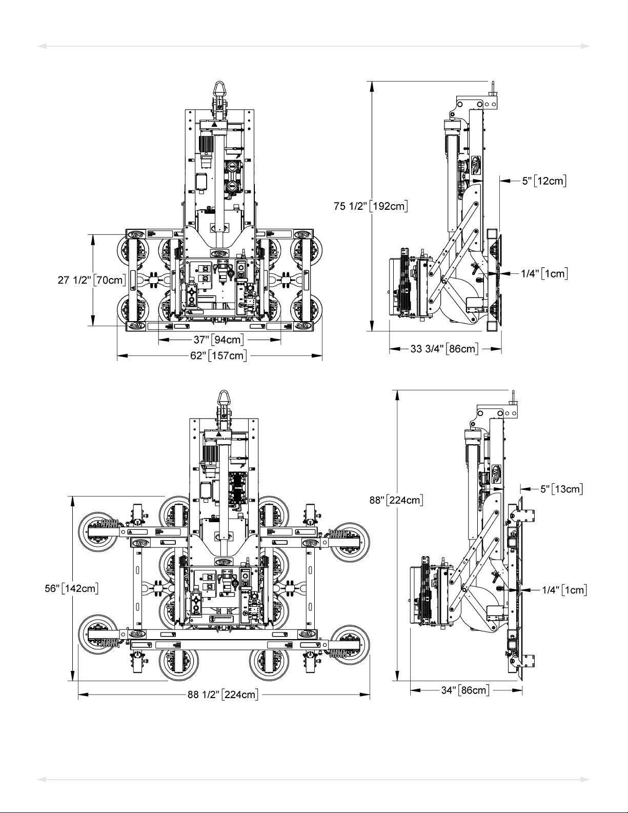
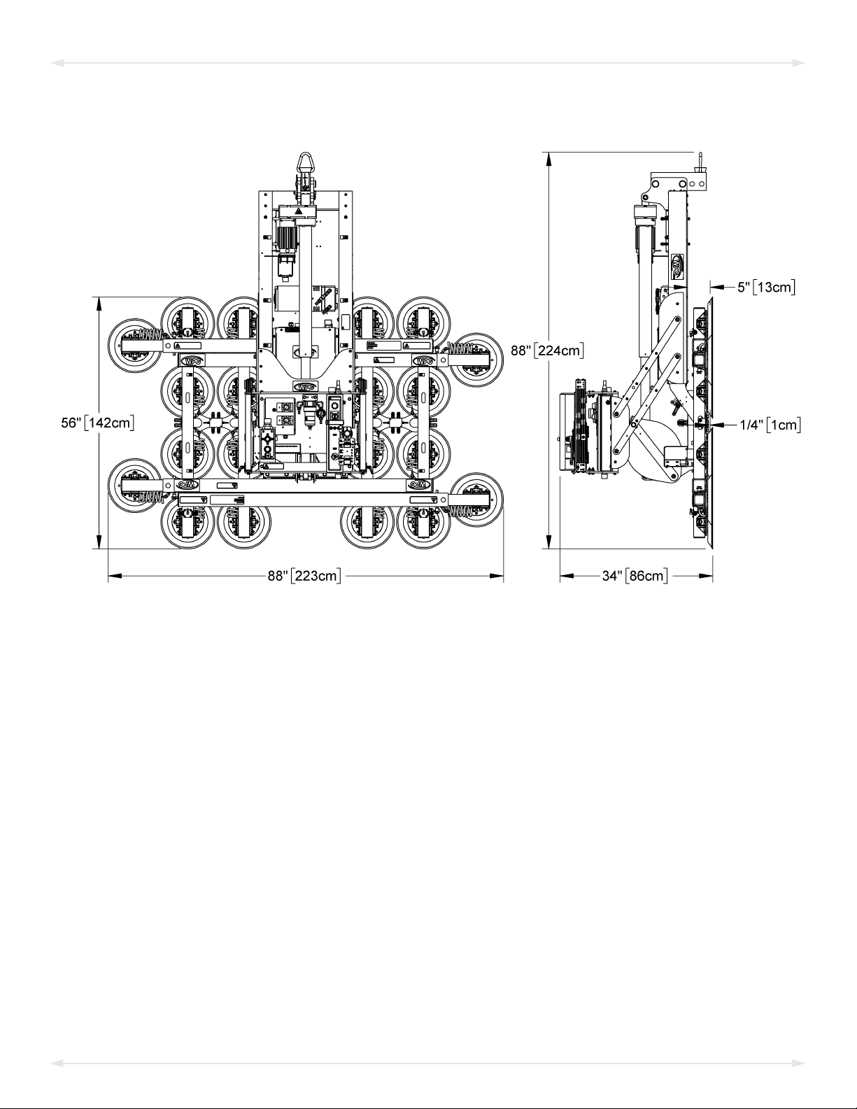
Pad Spread2
2...... These dimensions reflect pad configurations with the Maximum Load Capacity; other configurations are possible for lighter loads.
--------------------------------to outer edges---------------------------------
Length ‒Maximum 62" [157 cm] 140¼" [356 cm] 140½" [357 cm]
Length ‒Minimum 62" [157 cm] 64½" [164 cm] 88" [223 cm]
Width ‒Maximum 27½" [70cm] 56" [142 cm] 56" [142 cm]
Width ‒Minimum 27½" [70cm] 46¼" [117 cm] 56" [142 cm]
Maximum
Load Capacity3
3...... The Maximum Load Capacity is rated at a vacuum of 16" Hg [-54 kPa] on clean, smooth, nonporous flat surfaces with a friction coefficient of 1. Pad
compound, load rigidity, strength, surface conditions, overhang, angle, center of gravity and temperature can also affect the lifting capacity. A “qualified
person” should evaluate the effective lifting capacity for each use (see definition under “Rated Load Test” on page 28).
Per pad: 125 lbs [57 kg]
Total: 1,000 lbs [455 kg]
Per pad: 167 lbs [75.5 kg]
Total: 2,000 lbs [905 kg]
Per pad: 150 lbs [68 kg]
Total: 3,000 lbs [1,360 kg]
Lifter
Weight 565 lbs [257 kg] 700 lbs [318 kg] 740 lbs [336 kg]
Power
Source See serial label for specific AC voltage, frequency and amperage.
Rotation
Capability Manual, 360°, with latching at every 18° of revolution (when required)
Tilt
Capability4
4...... Specifications shown for 120V AC lifters;characteristics may vary for other voltages.
Powered, 90°, with adjustable electronic speed controller; Maximum speed = approx 20 seconds per tilt
travel in one direction; Maximum duty = 50 tilts per hour
Product
Options See separate instructions about options.
Operating
Elevation Up to 6,000' [1,828 m]
Operating
Temperatures 32° — 104° F [0° — 40° C]
Service
Life 20,000 lifting cycles, when used and maintained as intended5
5...... Vacuum pads, filter elements and other wear-out items are excluded.
ASME Standard
BTH-1 Design Category "B", Service Class "0" (see www.wpg.com for more information)
Rev 1.0/2-21 MRPTHD-AC: #350663
!!–CE–!! This symbol appears only when a CE Standard is different from other applicable standards. CE requirements are mandatory
in the European Union, but may be optional elsewhere.
SPECIFICATIONS