WPG QUADRA-TILT MRTA811LDC3 User manual

MRTA8-DC3: #351211
INTENDED FOR USE BY SKILLED
PROFESSIONALS • READ AND
UNDERSTAND BEFORE OPERATING
OPERATING
INSTRUCTIONS
QUADRA-TILT
ROTATOR, DC-VOLTAGE
WITH INTELLI-GRIP®
TECHNOLOGY
Available with REMOTE CONTROL SYSTEM
Model numbers: MRTA811LDC3 (shown),
MRTA810TDC3, MRTA810CDC3O
KEEP FOR FUTURE REFERENCE

Rev 8.0/12-19 MRTA8-DC3: #351211
SPECIFICATIONS .....................................................................................3
SAFETY...................................................................................................5
OPERATING FEATURES............................................................................6
ASSEMBLY..............................................................................................7
TOCHANGE THE PAD FRAME CONFIGURATION ..................................................9
Installing or Removing Extension Arms and Repositioning Vacuum Pads ........................11
Using Secondary Rotation Stops .......................................................................................12
Connecting/Disconnecting Vacuum Hoses .......................................................................13
INTENDED USE .....................................................................................14
LOAD CHARACTERISTICS...............................................................................14
OPERATING ENVIRONMENT..........................................................................15
DISPOSAL OF THE LIFTER .............................................................................15
OPERATION..........................................................................................16
BEFORE USING THE LIFTER...........................................................................16
Taking Safety Precautions .................................................................................................16
Selecting a Screen Language.............................................................................................16
Performing Inspections and Tests .....................................................................................17
Checking the 12-Volt Battery ............................................................................................17
Preparing to Use the Remote Control System ..................................................................18
TOATTACH THE PADS TO ALOAD ..................................................................19
Positioning the Lifter on the Load.....................................................................................19
Powering up the Lifter ......................................................................................................20
Sealing the Pads on the Load............................................................................................20
Reading the Vacuum Gauges ............................................................................................21
TOLIFT AND MOVE THE LOAD......................................................................22
About the Tilt Linkage.......................................................................................................22
Engaging or Disengaging Tilt Locks ...................................................................................23
Interpreting the Lift Light..................................................................................................24
Watching Vacuum Indicators ............................................................................................24
Controlling the Lifter and Load .........................................................................................25
In Case of a Power Failure.................................................................................................25
TOROTATE THE LOAD .................................................................................26
TOTILT THE LOAD ......................................................................................27
TABLE OF CONTENTS

MRTA8-DC3: #35121 Rev 8.0/12-192
TORELEASE THE PADS FROM THE LOAD .........................................................29
AFTER USING THE LIFTER.............................................................................30
Storing the Lifter ...............................................................................................................30
INSPECTIONS AND TESTS......................................................................32
INSPECTION SCHEDULE ................................................................................32
TESTING ...................................................................................................33
Lifter/Load Compatibility Test...........................................................................................33
Operational Tests ..............................................................................................................34
Vacuum Test......................................................................................................................34
Rated Load Test.................................................................................................................35
Remote Control System Test .............................................................................................35
MAINTENANCE ....................................................................................36
VACUUM PAD MAINTENANCE.......................................................................36
Pad-to-Load Friction Coefficient .......................................................................................36
Pad Inspection ..................................................................................................................36
Pad Cleaning .....................................................................................................................37
NOTIFICATION BUZZER BATTERY REPLACEMENT ...............................................37
12-VOLT BATTERY RECHARGE.......................................................................38
INTELLI-GRIP® DIAGNOSTIC CODES ...............................................................39
TOREPLACE SEALING RING IN VPFS10T PADS ...............................................43
REPLACEMENT PARTS...........................................................................44
LIMITED WARRANTY ............................................................................45
TOOBTAIN REPAIRS OR WARRANTY SERVICE...................................................45
TABLE OF CONTENTS

Product
Description
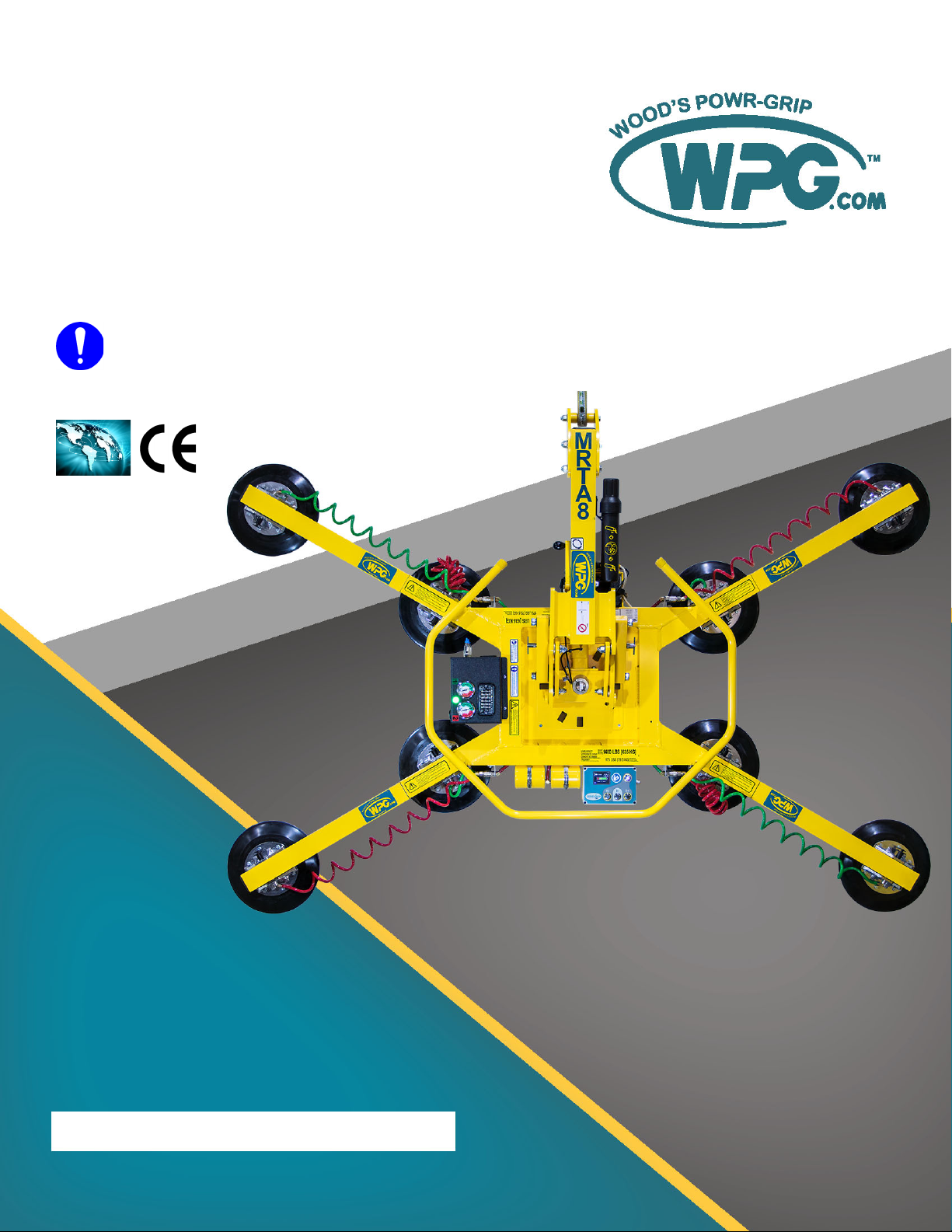
Designed for use with hoisting equipment, MRTA8-DC3 lifters support loads using vacuum and manipulate
loads using manual 360° rotation and mechanically assisted, manual 90° tilt motions.
Model
Number MRTA811LDC3 MRTA810TDC3 MRTA810CDC3O
Vacuum Pads1
1...... Available with other rubber compounds for special purposes (see www.WPG.com).
(8 each, standard rubber)
11" [28 cm] nom. diameter,
lipped (Model G3370)
10" [25 cm] nom. diameter,
with ring (Model VPFS10T2
2...... Standard with replaceable sealing rings for rough or textured surfaces (see “REPLACEMENT PARTS” on page 44).
)
10" [25 cm] nom. diameter,
concave (Model G0750)
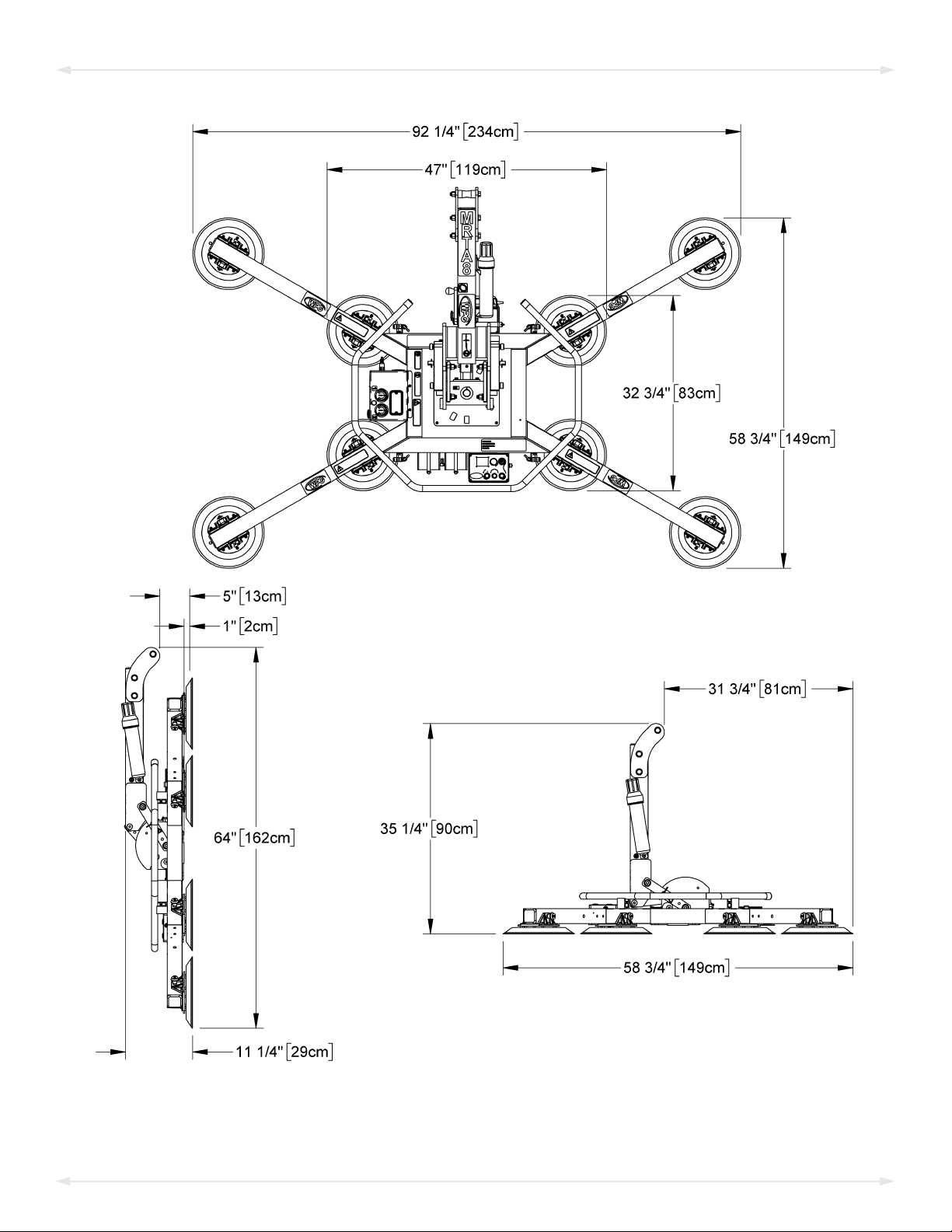
Pad Spread3
3...... The illustrations under “TOCHANGE THE PAD FRAME CONFIGURATION”on page 9 show the Pad Spread and Maximum Load Capacity for all approved
MRTA811LDC pad frame configurations.
---------------------------- (to outer edges) ----------------------------
Length ‒Maximum 104¾" [266 cm] 104" [264 cm] 102½" [260 cm]
Length ‒Minimum 47" [119 cm] 46" [117 cm] 44¾" [114 cm]
Width‒Maximum 58¾" [149 cm] 58" [147 cm] 56½" [143 cm]
Width ‒Minimum 12½" [32 cm] 11½" [29 cm] 10" [26 cm]
Maximum Load
Capacity4
4...... The Maximum Load Capacity is rated at a vacuum of 16" Hg [-54 kPa] on clean, smooth, nonporous flat surfaces with a friction coefficient of 1. Pad
compound, load rigidity, strength, surface conditions, overhang, angle, center of gravity and temperature can also affect the lifting capacity. A “qualified
person” should evaluate the effective lifting capacity for each use (see definition under “Rated Load Test” on page 35).
Per-Pad 175 lbs [79.5 kg] 150 lbs [68 kg] 150 lbs [68 kg]
Total with 4 Pads 700 lbs [320 kg] 600 lbs [270 kg] 600 lbs [270 kg]
Total with 8 Pads 1,400 lbs [635 kg] 1,200 lbs [545 kg] 1,200 lbs [545 kg]
Lifter
Weight 200 lbs [91 kg] 190 lbs [87 kg] 190 lbs [87 kg]
Power
System 12 volts DC, 4.5 amps
Battery
Capacity 7 amp-hours
Rotation
Capability Manual, 360°, with latching at each ¼ turn (when required)
Tilt
Capability
Manual, 90°, with four-bar tilt linkage that provides mechanical advantage and tilt locks that prevent tilt
motion when engaged
Product
Options
Available with Remote Control System – FCC, CE and ICC certified.
See separate instructions about other options.
Operating
Elevation Up to 6,000' [1,828 m]
Operating
Temperatures 32° — 104° F [0° — 40° C]
Service
Life 20,000 lifting cycles, when used and maintained as intended5
5...... Vacuum pads, filter elements and other wear-out items are excluded.
!!–CE–!! This symbol appears only when a CE Standard is different from other applicable standards. CE requirements are
mandatory in the European Union, but may be optional elsewhere.
Software
Version Intelli-Grip®7.6
ASME Standard
BTH-1 Design Category "B", Service Class "0" (see www.WPG.com for more information)
Rev 8.0/12-19 MRTA8-DC3: #351213
SPECIFICATIONS

MRTA8-DC3: #35121 Rev 8.0/12-194
Note: A standard MRTA811LDC3 is shown.
SPECIFICATIONS

Rev 8.0/12-19 MRTA8-DC3: #351215
SAFETY
Wear personal protective
equipment that is appropriate for
the load material. Follow trade
association guidelines.
Do not remove or obscure safety
labels.
Do not make any modifications to
the lifter (see “LIMITED
WARRANTY”).
Use the lifter only in an approved
“OPERATING ENVIRONMENT”(see
“INTENDED USE”).
Do not use a lifter that is damaged,
malfunctioning, or missing parts.
Do not use a lifter if the sealing
edge of any vacuum pad is cut or
otherwise damaged.
Do not use a lifter to lift cracked or
broken glass.
Do not exceed the Maximum
Load Capacity or lift loads the
lifter is not designed for (see
“INTENDED USE”).
Do not use a lifter if the
Maximum Load Capacity or
any safety label appears to be
missing or obscured.
Make sure the contact surfaces of
the load and vacuum pads are clean
before attaching the lifter (see
“MAINTENANCE”).
Position the vacuum pads correctly
on the load before lifting (see
“OPERATION: Positioning the Lifter
on the Load”).
Do not lift a load if any vacuum
indicator shows inadequate
vacuum.
Keep unauthorized personnel away
from the lifter, to avoid injury in
case of an unintended load release.
Do not touch the vacuum release
controls during a lift.
Do not allow people to ride on the
lifter or the load.
Do not lift a load higher than
necessary or leave suspended loads
unattended.
Do not position a loaded or
unloaded lifter over people.
Before servicing a powered lifter,
place the power control in the
inactive position and, when
possible, disconnect the power source.

MRTA8-DC3: #35121 Rev 8.0/12-196
Features shown here are underlined on their first appearance in each section following.
1 LIFT POINT 2 INSTRUCTION CANISTER 3 BATTERY CHARGER
4 VACUUM PAD with MOVABLE PAD MOUNT 5 CONTROL HANDLE 6 PADFRAME
7 EXTENSION ARM 8 INTELLI-GRIP® CONTROL UNIT 8a POWER BUTTON
8b “RELEASE” BUTTON 8c “ATTACH” BUTTON 8d “FUNCTION” BUTTON
8e LCD SCREEN with BATTERY GAUGE 9 VACUUM RESERVE TANKS 10 QUICK CONNECTOR
11 NOTIFICATION BUZZER
12 ENCLOSURE for VACUUM PUMP,
AIR FILTERS, CIRCUIT BOARD and
VACUUM SENSORS
12a STROBE LIGHT
12b VACUUM LIFT LIGHT 12c VACUUM GAUGES 13 TILT LOCK
14 BATTERY (hidden) 15 ROTATION RELEASE LEVER 16 LIFT BAR
Note: A standard MRTA811LDC3 model is shown. Although some of the following photos do not
show this specific lifter, they all illustrate how this kind of lifter functions.
OPERATING FEATURES

Rev 8.0/12-19 MRTA8-DC3: #351217
1)
2A 2B
Remove all restraints and save them with the shipping container for future use.
2) Suspend the lifter from appropriate hoisting equipment:
2.1)
Select a crane and/or hoist rated for the Maximum Load Capacity plus the
Lifter Weight.
Note: Any lifter use must comply with all statutory or regulatory standards for
hoisting equipment in your region.
2.2) Disengage any tilt locks or latches, and raise the lift bar (figs. 2A-C).
2.3) Attach the hoisting hook to the
lift point (figs. 2D-E).
2D 2E
Make sure
hook has
restraining latch
(circled).
2F
Only use rigging rated for Maximum Load
Capacity plus Lifter Weight.
Use
rigging (fig. 2F) as needed to
make sure the hook does not
interfere with the load.
ASSEMBLY
2C

MRTA8-DC3: #35121 Rev 8.0/12-198
2.4) Use the hoisting equipment to remove the lifter from the shipping container. Avoid
damaging the vacuum pads.
3B3A
3)
3C
3D
Connect the electrical connectors (figs. 3A-B and
figs. 3C-D).
If the lifter has a notification buzzer, install the 9-
volt battery as directed in “NOTIFICATION BUZZER
BATTERY REPLACEMENT”on page 37.
4)
4A
Assemble the pad frame for optimal load support
(see “TOCHANGE THE PAD FRAME CONFIGURATION”on
page 9). Remove the pad covers (fig. 4A) and save them
for future use.
5) Perform tests as required under “TESTING”on page 33.
ASSEMBLY

Rev 8.0/12-19 MRTA8-DC3: #351219
TOCHANGE THE PAD FRAME CONFIGURATION
ASSEMBLY

MRTA8-DC3: #35121 Rev 8.0/12-1910
Various pad frame configurations enable the lifter to match different load dimensions and
weights. The illustrations on the preceding page show all approved configurations. Pad Spread
and Maximum Load Capacities are listed for a standard MRTA811LDC3 lifter (see
“SPECIFICATIONS” on page 3 for other models).
Caution: Connect the vacuum pads to the 2 circuits of the dual vacuum system (marked “1” and
“2” in the preceding illustrations).
1)
Use only approved pad
frame configurations.
Choose an approved configuration to maximize
support across the load surface and to minimize load
overhang (see “LOAD CHARACTERISTICS”on page 14).
2) Install or remove the extension arms and reposition the movable pad mounts as needed
(see next page):
•
Securely position vacuum
hoses to avoid damage
during lifter operation.
To support the maximum load weight, you
must install all vacuum pads on the pad frame
and connect all vacuum hoses to the vacuum
pads, using the quick connectors.
• To support larger load dimensions, you must also install all extension arms on the
pad frame.
•
Disconnecting or
removing any vacuum
pad reduces lifting capacity.
To support smaller weights and dimensions,
you may remove some extension arms or
vacuum pads, and disconnect the
corresponding vacuum hoses (see
“Connecting/Disconnecting Vacuum Hoses” on page 13), provided the lifter still
has sufficient capacity to support the load in question.1
1..... Whenever a quick connector is disconnected, the corresponding vacuum pad does not contribute to the lifting capacity, whether or not the pad
is mounted on the pad frame.
ASSEMBLY

1A 2A
3A 4A
Rev 8.0/12-19 MRTA8-DC3: #3512111
Installing or Removing Extension Arms and Repositioning Vacuum Pads
1) Remove the cotterless hitch pin that secures the movable pad mount to the pad frame
(fig. 1A).
2)
6A
5A
Remove the vacuum pad from the pad frame (fig. 2A) and, if
necessary, disconnect the vacuum hose.
3) Insert the extension arm into the pad frame (fig. 3A).
4) Insert a cotterless hitch pin to secure the extension arm (fig.
4A).
5) Position the pad mount on the extension arm and, if necessary,
reconnect the vacuum hose (fig. 5A).
6) Insert a cotterless hitch pin to secure the pad mount (fig. 6A).
Notes: Repeat or reverse these steps to assemble or disassemble the
pad frame as needed. Store removed components in a clean, dry
location.
ASSEMBLY

MRTA8-DC3: #35121 Rev 8.0/12-1912
Using Secondary Rotation Stops
Align the secondary rotation stops for correct use of the pad frame in long, narrow
configurations.
ASSEMBLY

1A 2A
Rev 8.0/12-19 MRTA8-DC3: #3512113
Connecting/Disconnecting Vacuum Hoses
Make sure quick
connectors seal
completely and all vacuum
hoses function correctly (see
“Vacuum Test” on page 34)
To connect a vacuum hose, push the male and female ends of
the quick connector together until they lock (fig. 1A).
To disconnect a vacuum hose, move the release ring on the
female end until the quick connector separates (fig. 2A).
4A3A
Make sure all hoses are
connected correctly: Green
hose to circuit 1 (fig. 3A) and
red hose to circuit 2 (fig. 4A).
5A
The 2 vacuum gauges are
labeled to indicate the
related circuits (fig. 5A).
Note: The gauge face colors
do not correspond with the
circuit colors.
ASSEMBLY

MRTA8-DC3: #35121 Rev 8.0/12-1914
INTENDED USE
LOAD CHARACTERISTICS
Do NOT lift explosives, radioactive
substances or other hazardous materials.
Make sure the vacuum lifter is intended
to handle each load according to these
requirements:
• The load weight must not exceed the Maximum Load Capacity.
• The load must be a single piece of relatively nonporous material with a flat and
relatively smooth contact surface.1, 2To determine whether the load is too porous or
rough, perform a “Lifter/Load Compatibility Test” on page 33.
• The load's contact surface must be able to obtain a friction coefficient of 1 with the
lifter's vacuum pads (see “Pad-to-Load Friction Coefficient” on page 36). Otherwise, the
capacity should be derated appropriately.
• The load's surface temperature must not exceed the Operating Temperatures.3
• The load's minimum length and width are determined by the current Pad Spread
(see “SPECIFICATIONS” on page 3).
• The load's maximum length and width are determined by its allowable overhang.4
• 1½" [3.8 cm] is the allowable load thickness at Maximum Load Capacity.5The load
must be positioned correctly on the lifter and tilt locks or latches must be used
when appropriate (see “OPERATION”). If not, the allowable load thickness would be
reduced.6
Note: Standard vacuum pads can stain or deform load surfaces with light colors or soft coatings.
Test such surfaces for damaging effects before using the lifter on them.7
1..... Although concave vacuum pads can also attach to some curved loads, curvature can reduce lifting capacity. Contact WPG for more information.
2..... A “single piece” of material includes curtainwall assemblies, unitized glazing systems and similar construction units.
3..... Vacuum pads made from a heat-resistant rubber compound can enable you to lift loads with higher surface temperatures. Contact WPG or an
authorized dealer for more information.
4..... The allowable overhang is the amount of load material that can extend sideways beyond the vacuum pad without breaking or otherwise being
damaged. This depends on the load material, its thickness, and the angle of handling (if any). Since every material has different physical
properties, the allowable overhang must be evaluated separately for each load type. Contact WPG or an authorized dealer for more
information.
5..... However, the allowable thickness increases as load weight decreases. Contact WPG for more information.
6..... Pad Spacers can reduce the stability of upright loads and allowable load thickness. Contact WPG for more information.
7..... Alternative rubber compounds are available for these purposes. Contact WPG or an authorized dealer for more information.

Rev 8.0/12-19 MRTA8-DC3: #3512115
OPERATING ENVIRONMENT
Make sure the vacuum lifter is intended for use in each work environment, given the following
restrictions:
•
Never use lifter in dangerous
environments.
Metal particles and similar
environmental contaminates
could result in vacuum pump failure.
This lifter is not intended for any environment
that is dangerous to the operator or damaging
to the lifter. Avoid environments containing
explosives, caustic chemicals and other
dangerous substances.
• The work environment is limited by the Operating Elevation and Operating
Temperatures.1, 2
• The lifter is not designed to be watertight.
Moisture can result in
reduced lifting capacity.
Do not
use it in rain or otherunsuitable conditions.
DISPOSAL OF THE LIFTER
After the Service Life of the vacuum lifter has ended (see “SPECIFICATIONS” on page 3), dispose
of it in compliance with all local codes and applicable regulatory standards.
Note: Special disposal regulations may apply to the battery.
1..... Although lifter use may be possible at higher elevations, lifting capacity is reduced whenever the lifter is unable to attain vacuum in the green
range on the vacuum gauges. Contact WPG for more information.
2..... Special provisions may allow the lifter to operate outside the specified temperature range. Contact WPG for more information.
INTENDED USE

MRTA8-DC3: #35121 Rev 8.0/12-1916
OPERATION
BEFORE USING THE LIFTER
Determine whether the vacuum lifter is capable of each intended task (see “SPECIFICATIONS”
on page 3 and “INTENDED USE” on page 14). Then complete the following preparations:
Taking Safety Precautions
•
Read all directions and safety
rules before using lifter.
Always wear appropriate
personal protective equipment.
Be trained in all industry and regulatory
standards for lifter operation in your region.
• Follow trade association guidelines about
precautions needed for each load material.
Selecting a Screen Language
When the lifter is powered up for the first time, the Intelli-Grip®
control unit prompts the operator to select a language for the LCD
screen. Use the buttons, as follows:
• To scroll down, press the “release” button ( ).
• To scroll up, press the “attach” button ( ).
• To select a language, press the “function” button ( ).1
Note: A similar process is used to navigate all menus.
1..... To change the language again, refer to the “INTELLI-GRIP®OPERATOR MENUS” section of the SERVICE MANUAL.

Always check battery
energy before every lift.
Rev 8.0/12-19 MRTA8-DC3: #3512117
Performing Inspections and Tests
• Follow the “INSPECTION SCHEDULE” on page 32 and “TESTING”on page 33.
•
Examine air filters regularly
and service when needed.
Service the 2 air filters whenever a bowl contains
liquid or other contaminates, or an element
appears dirty (see “AIR FILTER MAINTENANCE” in
SERVICE MANUAL).
•
Make sure
notification
buzzer can be
heard over noise
at operator
position.
Make sure the notification buzzer is clearly
audible at the maximum distance between the
operator and the lifter, despite any barriers or
obstacles.1, 2
Checking the 12-Volt Battery
While the lifter is powered up, a battery gauge on the LCD
screen displays the current energy level.3, 4
• If battery energy is in the red range, discontinue lifter
use and charge the battery (see “12-VOLT BATTERY
RECHARGE”on page 38).
• If battery energy continues to decrease and you try to
attach the lifter to a load, the notification buzzer will
sound continuously and the LCD screen will display “Lockout (low 12V battery)”, along
with a diagnostic code (see “INTELLI-GRIP® DIAGNOSTIC CODES”on page 39. In this case, you
must charge the battery in order to continue using the lifter.
1..... Maximum buzzer volume is 95 dBA at 2' [60 cm]. If CE Standards apply, consult EN 7731 to make sure the notification buzzer is compliant.
2..... The “Vacuum Test” on page 34 provides a convenient opportunity to check this.
3..... If the lifter remains in “Power Save” mode for a long time, the pump will run periodically to test the battery.
4..... If the battery charger is connected to an AC power source, the reading on the battery gauge will not be accurate and “Replace 12V battery” may
appear on the LCD screen, because the system cannot accurately evaluate the battery.
OPERATION

MRTA8-DC3: #35121 Rev 8.0/12-1918
Preparing to Use the Remote Control System
1 EMERGENCY DISCONNECT BUTTON
2 TRANSMISSION INDICATOR LIGHT
3 “RELEASE” BUTTON
4 “ATTACH” BUTTON
5 POWER/“FUNCTION” BUTTON
1A
The optional radio transmitter (fig. 1A) and radio
receiver enable you to activate the lifter's “attach”
and “release” functions at distances up to 250' [76 m],
provided you have a clear and direct view of the lifter and
its status indicators.
To operate a lifter remotely, follow these safety rules:
• Visually verify the status of the lifter and load prior
to lifting.
Make sure nearby personnel are aware of
intended remote control actions.
• Monitor the lifter at all times to make sure it is
functioning as intended.1
• Be sure the load is lowered and supported correctly
before releasing it (see following sections).
Note: To prevent any radio transmission, press the
emergency disconnect button.2
1..... The Remote Control System is designed to prevent multiple lifters from responding. Nevertheless, radio-controlled lifters should be tested to
make sure each transmitter controls only one lifter.
2..... To reset the emergency disconnect button, twist the button clockwise and allow it to spring outward to its original position.
OPERATION
Other manuals for QUADRA-TILT MRTA811LDC3
1
This manual suits for next models
5
Table of contents
Other WPG Industrial Equipment manuals