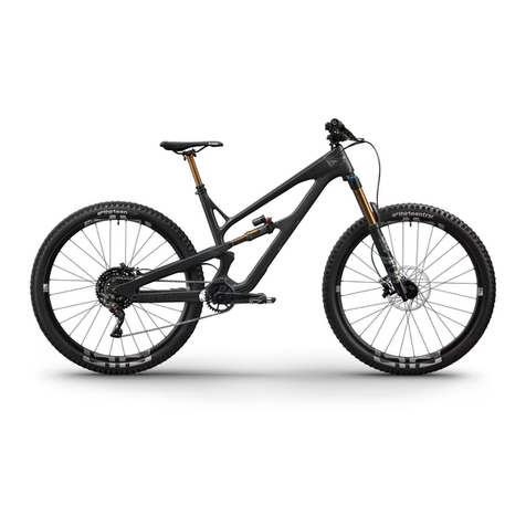
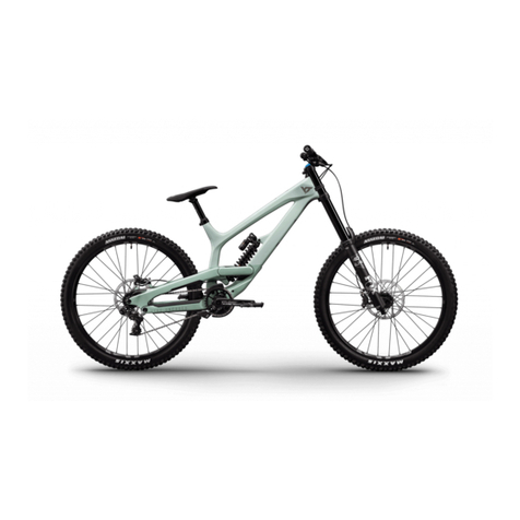
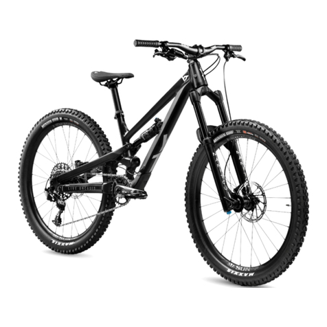
YT Industries TUES 27 Carbon User manual

read first – then unpack
erst lesen – dann auspacken
D’abord lire – ENSUITE DEBALLER
rTFM
2020

1
4
5
2
3
6
7
8
9
10
11
12
13
14
14
15 16
17
18 19
20
21
22
23
24
26
25
28
30
31
32
33
34
35
27
29
SUSPENSION FORK /
FEDERGABEL /
FOURCHE
FRAME /
RAHMEN /
CADRE
WHEEL /
LAUFRAD /
ROUE

FR
Intro 48
INSTRUCTIONS DE MONTAGE 50
Insertion Maximale de la Tige de Selle 59
TABLEAU DES COUPLES DE SERRAGE 61
RÉGLAGES APRèS L’ASSEMBLAGE 64
CONSEILS D’UTILISATION DE CADRES DE
VÉLOS EN FIBRE DE CARBONE (CFRP) 66
Triangle Arrière Démontage ET Montage 68
EN DE FR
1Toptube Oberrohr Tube Supérieur
2Downtube Unterrohr Tube Oblique
3Seattube Sitzrohr Tube de selle
4Chainstay Kettenstrebe Base
5Seatstay Sitzstrebe Hauban
6Headtube Steuerrohr Tube de direction
7Rear Shock Dämpfer Amortisseur
8Drop out Ausfallende Pattes
9Saddle Sattel Selle
10 Seatpost Sattelstütze Tige de selle
11 Seatpost Clamp Sattelstützenklemme Collier de serrage de tige de selle
12 Front brake Bremse vorne Frein avant
13 Rear brake Bremse hinten Frein arrière
14 Disc Bremsscheibe Disque
15 Cassette Zahnkranz Cassette
16 Chainguide Kettenführung Guide-Chaîne
17 Chainring Kettenblatt Plateau
18 Rear Derailleur Schaltwerk Dérailleur arrière
19 Chain Kette Chaîne
20 Crankset Kurbel Pédalier
21 Pedal Pedal Pédale
22 Crownnotepad Gabelkrone Té
23 Stanchions Standrohr Plongeur
24 Casting Tauchrohr Fourreaux
25 Stem Vorbau Potence
26 Brake Lever Bremshebel Levier de frein
27 Handlebar Lenker Cintre
28 Shifter Schalthebel Commande de Vitesses
29 Headset Steuersatz Jeu de direction
30 Quick-release Schnellspanner-Steckachse Blocage de Roue
31 Hub Nabe Moyeu
32 Spoke Speiche Rayon
33 Rim Felge Jante
34 Tire Reifen Pneu
35 Valve Ventil Valve
EN
Intro 04
ASSEMBLY INSTRUCTIONS 06
INFORMATION ON THE HANDLING of the seat post 15
Chart: Torques 17
ADJUSTMENTS AFTER ASSEMBLY 20
INFORMATION ON THE HANDLING AND USE OF
BIKE FRAMES MADE FROM CARBON (CFRP) 22
rear triangle Disassemly and Assembly 24
DE
Intro 26
Aufbauanleitung 28
HINWEISE ZUR HANDHABUNG der sattelstütze 37
tabelle: Drehmomente 39
Einstellungen nach dem Aufbau 42
HINWEISE ZUR HANDHABUNG UND NUTZUNG VON
BIKE-RAHMEN AUS DEM WERKSTOFF CARBON (CFK) 44
Hinterbau demontage und Montage 46

04 yt
PUT YOUR TRUST IN YT: CHECK.
ORDERED YOUR BIKE: CHECK.
GOOD TIMES: CHECK.
Good Job.
congrats & thanks for that!

yt 05
EN
And now you’re ready to ride! Well, almost. First you have to
uncrate this machine, of course. Do it properly and you’ll be
able to use the YT BikeBox again, for transporting your YT or
to send it in for a service. And setting it up? With this manual
easier than you might think.
You’ve guessed it, a manual is just so much more than drifting
on your rear wheel. This one is a step-by-step guide for setting
up and maintaining your ride. For both involve technical knowl-
edge,aswellascraftsmanship.That’swhywe’lltalkyouthrough
all basic settings and maintenance recommendations for your
YT: Follow the instructions and everything will run smoothly.
Needless to say, that this manual is not meant to provide the
knowledge or skills required for professional bike assembly
and it won’t enable you to start building a bike from single
pieces or repairing crucial equipment. But you don’t have to
be MacGyver either.
Together we’ll get the job done!
You don’t feel ready to carry out set-up, maintenance and
repair yourself? No need to break out in cold sweat. Play it safe
and hand the job over to a specialist workshop. Or get in touch
with us: We’ll take care of you. Our service will stand by your
side, answering your questions.
There’s only one thing left to say: This will happen within the
scope of our warranty and liability limitatons and exclusions.
When dealing with inquiries by phone or mail, important details
may be overlooked or get lost in translation. We can never be
100 % sure, that the type and scope of the required work have
been described correctly and to their full extend. Furthermore
there’s always a degree of uncertainty in remote diagnostics
and of course we cannot control whether you have followed
our instructions appropriately. So we hope it’s obvious and
reasonable that we can’t compensate and accept liability for
damages and accidents that are results of self-executed re-
pairs or non-professional maintenance. In either of these cases
warranty of components shall be void. Fair enough, isn’t it?
Get in touch with us! service@yt-industries.com
PUT YOUR TRUST IN YT: CHECK.
ORDERED YOUR BIKE: CHECK.
GOOD TIMES: CHECK.
TIP: Don’t ditch the YT BikeBox, keep it, incl. all additional material.
so you can safely repack your bike for transport again.
06 yt
UNBOX YOUR BIKE
Cut the packaging straps using wire cutters
or a box cutter. Just make sure not to dam-
age the YT BikeBox. Now you can pull out
the flaps and open it.
Lift the wheels out of the box. Put the wheels
in a safe place on the side of the box.
Now you can lift your bike upwards, out of
the box.
Place the frame on the front/rear axle stand.
Make sure the bike is standing safely!
1.1
1.4
1.2
1.3

yt 07
EN
HANDLEBAR ASSEMBLY
Cut the zip ties with a wire cutter. Grease the threads of the screws. Mount the
stem base plate on the upper fork crown using
the shorter, rear-side bolts (Allen key 5 mm).
Tighten the bolts to the recommended torque
(refer to the black box on page 8).
Using the longer bolts, mount the stem
clamps to the upper fork crown through the
holes in the middle of the stem base plate.
Make sure to begin in this order and tighten
the bolts to the specied torque. Also en-
sure that there is no gap between the stem
clamps and the stem base plate in this step
(zero gap).
Now mount the forward bolts of the stem
clamps to the base plate. Pay attention to the
torque recommendations, even clamp gaps,
and the correct alignment of the handlebar.
The adjustment graphics will help you with
this.
PRO RACE // PRO
RENTHAL FATBAR
2.1.1
2.1.4
2.1.2
2.1.5 2.1.6
2.1.3

08 yt
RaceFace Direct Mount:
Fork crown screws // 12 Nm
Handlebar clamp screws// 9 Nm
Renthal Integra II:
Fork crown screws // 10 Nm
Handlebar clamp screws // 6 Nm
Remove the stem bolts from the upper fork
crown (Allen key 5 mm)
Put the screws in the stem then place the
handlebar and the stem on the upper fork
crown.
Mount the stem on the upper fork crown
(5 mm Allen key). Tighten the screws in an X
pattern. Do it step by step with just one turn
per screw at a time.This is the only way to
achieve an even clamping of the bolts.
Please follow the
torque specifications of
the manufacturers:
Torque the bolts exactly to the specications
of the manufacturer of the stem and / or han-
dlebar (refer to the black box on the right of
this page). Make sure the gaps in the clamp
are even and that the handlebar is centered
correctly – the adjustment graphics will help
you with this.
2.2.1 2.2.2 2.2.3
2.2.4
COMP // BASE
RACEFACE ATLAS/ CHESTER DIRECT MOUNT
HANDLEBAR ASSEMBLY

yt 09
Rear derailleur screw // 11 Nm
Please follow the
torque specifications of
the manufacturers:
EN
Make sure the bike is standing safely on the
rear axle stand.
Turn the rear axle stand on its side. Carefully
cut the cable tie using a wire cutter and re-
move the bubble wrap and the foam transport
protection from the chainstay.
Mount the rear derailleur on the derailleur
hanger (Allen key 5 mm). Please make sure
the bolt is perpendicular to the hanger to avoid
damaging the thread.
REAR DERAILLEUR ASSEMBLY
Tighten the rear derailleur screw using the
torque wrench. Make sure that the rear de-
railleur stop sits at the derailleur hanger stop.
Hold the derailleur with your second hand to
avoid a twisting of the derailleur and a gap.
3.4
3.1 3.2 3.3

10 yt
PREPARING
REAR WHEEL ASSEMBLY
Remove the cardboard packaging of both
wheels.
Remove the frame cover from the main frame.
Unscrew the rear wheel axle from the frame
and remove the axle´s transport protection.
Remove the rear axle stand from the rear axle.Open the rear derailleur cage and activate the
CAGE LOCK by pressing the small button with
the lock symbol on it.
Pull the spacer out of the rear brake caliper.
Please keep it for future bike transports.
4.3
4.1
4.4
4.2
4.5

yt 11
EN
Place the rear wheel in the frame. Make sure
to place the chain on the smallest cog of the
cassette. Carefully pull the shifter rearwards
to make the insertion easier.
Guides in the frame will help you align the wheel
properly. Secure the rear wheel with the rear
wheel axle and tighten it using the torque
wrench.
Press the derailleur cage forwards to release
the CAGE LOCK. Once released, carefully
guide the cage rearwards until it puts tension
on the chain.
REAR WHEEL ASSEMBLY
Rear wheel axle // 15 Nm
Please follow the
torque specifications of
the manufacturers:
5.1 5.2 5.3

12 yt
Unscrew the front wheel axle from the fork
and remove it.
FRONT WHEEL ASSEMBLY
PREPARING
Remove the front axle stand from the front
wheel axle.
Pull the spacer out of the brake caliper. Please
keep it for future bike transports.
Remove the cardboard packaging of both
wheels.
6.1
6.3 6.4
6.2

yt 13
EN
Check the torque of the clamping bolts with
a torque wrench.
Insert the front wheel in the fork dropouts.
Make sure the brake rotor is centered in the
brake caliper to avoid damages.
Insert the front wheel axle and tighten it. Use
a torque wrench to ensure that the front wheel
is properly secured.
FRONT WHEEL ASSEMBLY
Clamp the front wheel axle in the fork by tight-
ening the 4 clamping bolts in an alternating
pattern, one turn per bolt at a time.
Airsprung forks and shocks have
to be lled with the correct air pres-
sure before use! That’s why we have
included a shock pump to your
package: Please read the manu-
facturer manuals to learn how it
works.
FOX
Please follow the
torque specifications of
the manufacturers:
Axle // 3 Nm
Axle clamping bolts // 3 Nm
7.3
7.4
7.1 7.2

14 yt
PEDAL ASSEMBLY
Attach the pedals to the cranks using an allen
wrench. Apply some grease to the threads, if
there are washers make sure to use them!
Please note that there’s a right and a left
pedal.
The non-drive side pedal has reverse thread-
ing and is therefore tightened counterclock-
wise.Tighten the pedals with a torque of 30 –
35 Nm.
Unscrew the brake lever clamps (Torx T25) and
remove the attachments of the brake and shift
cables
Swap the brake levers to have the front brake
on your right and the rear brake on your left
side.
Mount the brake levers on your handlebar with
the brake lever clamps. Make sure the clamp
and the break t neatly into another and to
leave no gap (zero gap).
Make sure the levers are correctly aligned and
tighten them with a torque wrench (5 – 6 Nm
for aluminum bars; 2,8 – 3,4 Nm for carbon
bars).
SRAM BRAKE SWAP
8.1
8.2
9.1
9.3 9.4
9.2

yt 15
min 10 cm
mAX 15 cm
Once you have properly adjusted your seat
post height, tighten the seat post clamp with a
torque of 6 – 7 Nm.
10.3
We added a rubber seal to your ToolBox. Slide
it onto the seat post right above the clamp
and tighten the bolt to keep the dirt out.
10.2
EN
The minimum insertion depth of the seat post
is 10 cm. If you insert less, the frame can break
under load. Please also notice the maximum
insertion depth and do not insert the seat
post deeper into the seat tube, otherwise it
may cause damage to the frame in case of
heavy impact.
INSERTION DEPTH OF THE SEAT POST
TUES 27 Carbon ( MK3)
S – L: 12 cm
XL – XXL: 14 cm
TUES 27 Aluminum (MK3)
S – XXL: 13 cm
TUES 29 Carbon (MK3)
Regular: 13 cm
Long: 13 cm
X-Long: 16 cm
MAXIMUM
INSERTION DEPTH
OF THE SEAT POST
10.1

16 yt
IT´S
DONE

yt 17
EN
Bottom bracket 33 – 41 Nm
Brake caliper screw to frame and fork 9.5 Nm
Shifter 2.5 – 4 Nm
Disc brake bolts to hub 6 Nm
Rear derailleur (xing bolt) 11 Nm
Rear derailleur (clamp bolt) 4 – 5 Nm
Brake lever 2.8 – 3.4 Nm
Cassette retainer ring 40 Nm
Handlebar Clamp see manufacturer Specifications
Stem (steerer tube clamping) see manufacturer Specifications
Seat Post Clamp 6 – 7 Nm
Chain ring bolts 12 – 14 Nm (Steel)
8 – 9 Nm (Aluminum)
Pedals 30 – 35 Nm
Lock-on grip bolts 2.5 – 4 Nm
Shock bolts 10 – 12 Nm
TORQUES
CAUTION!
These specications are only guidelines. As a rule, you should always observe the manufacturers’
instructions. These have also been included or can be found on the website of the respective
manufacturer.

18 yt
Unbolt the handlebar from the stem. Slide the
rubber protector over the brake and dropper
post levers and wrap the handlebar in protec-
tive material. Insert the handlebar all the way
into the slot provided in the front axle stand.
Take care not to damage any cables or hoses.
Now install the remaining carton protectors
on the frame.
Place the bike IN the BikeBox on the front
and rear axle stands. Place the wheels in the
slots provided in the bottom of the BikeBox.
The wheel covers should face the frame. Now
secure the wheels, frame, and handlebar with
the Top Box.
Attach the wheel covers on the side of the
brake rotor and then join the two wheels to-
gether with a zip tie. Attach the wheel spacer
to the front wheel with a zip tie (see illustra-
tion).
Attach the foam wrappers to the frame. Se-
cure the chain with a zip tie to avoid damages.
Remove the derailleur from the derailleur
hanger to avoid causing any damage to the
frame. Wrap the derailleur in bubble-wrap and
secure it with a zip tie.
Release all the air from the fork before you
continue. Attach a foam wrapper to the fork
bridge with a zip tie. Also protect the fork legs,
either with carton or foam wrappers.
SHIPMENT / SERVICE
PACK YOUR BIKE
1. 2. 3.
5. 6.4.

yt 19
EN
WRAP ALL SENSITIVE AREAS WITH
PROTECTIVE MATERIAL. PREVENT
ANY UNWANTED CONTACT BETWEEN
THE FRAME AND THE COMPONENTS,
TO AVOID CAUSING ANY DAMAGE
DURING TRANSPORT.
If this is what it looks like in
your BikeBox, you’ve done it
right. The illustrations show
exactly how all the different
components should be or-
ganized.
Packed like this, your bike
will travel safely and reach
us in good condition.
ALL
BOXED
UP
SHIPMENT / SERVICE

20 yt
ADJUSTING THE SUSPENSION ELEMENTS
(REAR SHOCK AND SUSPENSION FORK)
The suspension elements we use allow for a variety
of adjustments. When making adjustments, please
note the detailed instructions of the suspension
element manufacturer. You can find up-to-date
information on their websites:
FOX: http://www.ridefox.com
RockShox: http://www.sram.com/en/rockshox
CAUTION! NEVER OPERATE YOUR BICYCLE
WITH INSUFFICIENT OR EXCESS AIR
PRESSURE! THIS COULD RESULT IN DAMAGE
TO THE FORK OR SHOCKS.
BASIC SETTINGS
The weight of the rider and his position on the bi-
cycle determine the adjustment criteria for the rear
shock and suspension fork. When sitting on the bike,
the suspension will compress to a certain degree –
the so-called ″sag″. Sag should be between 25 – 30 %
for Enduro bikes, between 30 – 40 % for Downhill
bikes, and between 10 – 20 % for Dirt bikes. The ″sag
value″ that corresponds to your riding style is best
determined with a few test rides. Test rides and per-
sonal preferences will also determine the settings of
the compression and rebound speeds of the suspen-
sion elements.
CAUTION! PLEASE NOTE
Your bike’s handling is influenced by each and every
adjustment to the suspension elements – therefore,
please be careful on your rst test rides to avoid
crashes. Avoid any adjustments that could lead to
the suspension elements frequently bottoming out.
They will thank you with a long service life. If you are
uncertain of anything or have any questions, do not
hesitate to contact us at:
GET TO KNOW YOUR BIKE
Familiarize yourself with your new bike. Verify once
again that all screws are tightened to the correct
torque. Our bikes are equipped with modern disc
brake systems with exceptional braking performance.
In addition, the braking performance increases after a
short break-in period. Try to get used to the braking
response and how it differs when riding over various
surfaces. Position the brake levers at your ngertips
so that they can be pulled without excessive effort.
The same applies to the shifters. Shift smoothly and
without applying too much pressure on the pedals.
This will help protect your drive train components.
Please choose a safe and familiar terrain for your ini-
tial test and training rides. You can nd all you need to
know about your bike in our ″SAFETY FIRST.″- manual
as well.
Familiarize yourself with the bike manual before
getting on your bike the rst time.
BEFORE EACH RIDE
By nature, mountain bikes are placed under a lot of
strain. The components of the bike react differently
to stresses, from wear and tear to material fatigue.
Individual components may fail without warning.
Please check your bike regularly for signs of damage
and/or have your bike periodically inspected.
CHECK BEFORE EVERY RIDE
• the seatpost and wheels are rmly secured in
the frame and fork.
•the wheels spin freely.
•the air pressure in the tires, the tension of the
spokes and the hub bearing play.
•the brake function.
•for signs of material fatigue (deformations,
fractures, cracks, signs of impact, etc.).
•all additional components for stability and
operational safety.
•the required torques for all screws.
Do not ride even if only one of the possible defects
is present.
CAUTION! VIBRATIONS THAT OCCUR WHEN
RIDING YOUR MOUNTAIN BIKE CAN LEAD TO
SCREWS LOOSENING (EVEN FOR SCREWS
WITH THREADLOCKER ADHESIVE)!
IN THE EVENT OF A CRASH
Crashes place a lot of strain on your bike’s materi-
al and components. Therefore, before you continue
your ride, check your bike for damage and impaired
functions (see ″Check Before Every Ride″).
Do not continue your ride even if only one of the
possible defects is present. If you are uncertain of
anything or have any questions, do not hesitate to
contact us directly at:
RIDING ON PUBLIC ROADS
IN GERMANY
The German Road Trafc Licensing Regulations
(Straßenverkehrs-Zulassungs-Ordnung, StVZO) dic-
tate the following safety devices when operating
bicycles on public roads:
•A braking and lighting system and a bright
sounding bell.
•Furthermore, every cyclist is obligated to maintain
his vehicle in a roadworthy condition and a state
that is safe for riding.
We would like to explicitly point out that our bikes
are not in compliance with the German road trafc
licensing regulations!
Read more about this topic in the ″SAFETY
FIRST.″-handbook.
ADJUSTMENTS
AFTER ASSEMBLY
This manual suits for next models
3
Table of contents
Languages:
Other YT Industries Bicycle manuals

YT Industries
YT Industries Jeffsy User manual

YT Industries
YT Industries rtfm. User manual

YT Industries
YT Industries RTFM JEFFSY Instruction sheet

YT Industries
YT Industries Jeffsy Primus User manual

YT Industries
YT Industries DIRTLOVE User manual

YT Industries
YT Industries TUES User manual

YT Industries
YT Industries TUES FR User manual

YT Industries
YT Industries TUES MKIII User manual

YT Industries
YT Industries Capra MX CORE 3 Instruction sheet