YT Industries TUES User manual

read first – then unpack
erst lesen – dann auspacken
D’abord lire – ENSUITE DEBALLER
rTFM
2021

FR
Intro 48
INSTRUCTIONS DE MONTAGE 50
Insertion Maximale de la Tige de Selle 59
TABLEAU DES COUPLES DE SERRAGE 61
RÉGLAGES APRèS L’ASSEMBLAGE 64
CONSEILS D’UTILISATION DE CADRES DE
VÉLOS EN FIBRE DE CARBONE (CFRP) 66
Triangle Arrière Démontage ET Montage 68
EN DE FR
1Toptube Oberrohr Tube Supérieur
2Downtube Unterrohr Tube Oblique
3Seattube Sitzrohr Tube de selle
4Chainstay Kettenstrebe Base
5Seatstay Sitzstrebe Hauban
6Headtube Steuerrohr Tube de direction
7Rear Shock Dämpfer Amortisseur
8Drop out Ausfallende Pattes
9Saddle Sattel Selle
10 Seatpost Sattelstütze Tige de selle
11 Seatpost Clamp Sattelstützenklemme Collier de serrage de tige de selle
12 Front brake Bremse vorne Frein avant
13 Rear brake Bremse hinten Frein arrière
14 Disc Bremsscheibe Disque
15 Cassette Zahnkranz Cassette
16 Chainguide Kettenführung Guide-Chaîne
17 Chainring Kettenblatt Plateau
18 Rear Derailleur Schaltwerk Dérailleur arrière
19 Chain Kette Chaîne
20 Crankset Kurbel Pédalier
21 Pedal Pedal Pédale
22 Crownnotepad Gabelkrone Té
23 Stanchions Standrohr Plongeur
24 Casting Tauchrohr Fourreaux
25 Stem Vorbau Potence
26 Brake Lever Bremshebel Levier de frein
27 Handlebar Lenker Cintre
28 Shifter Schalthebel Commande de Vitesses
29 Headset Steuersatz Jeu de direction
30 Quick-release Schnellspanner-Steckachse Blocage de Roue
31 Hub Nabe Moyeu
32 Spoke Speiche Rayon
33 Rim Felge Jante
34 Tire Reifen Pneu
35 Valve Ventil Valve
EN
Intro 04
ASSEMBLY INSTRUCTIONS 06
INFORMATION ON THE HANDLING of the seat post 15
Chart: Torques 17
ADJUSTMENTS AFTER ASSEMBLY 20
INFORMATION ON THE HANDLING AND USE OF
BIKE FRAMES MADE FROM CARBON (CFRP) 22
rear triangle Disassemly and Assembly 24
DE
Intro 26
Aufbauanleitung 28
HINWEISE ZUR HANDHABUNG der sattelstütze 37
tabelle: Drehmomente 39
Einstellungen nach dem Aufbau 42
HINWEISE ZUR HANDHABUNG UND NUTZUNG VON
BIKE-RAHMEN AUS DEM WERKSTOFF CARBON (CFK) 44
Hinterbau demontage und Montage 46
1
4
5
2
3
6
7
8
9
10
11
12
13
14
14
15 16
17
18 19
20
21
22
23
24
26
25
28
30
31
32
33
34
35
27
29
SUSPENSION FORK /
FEDERGABEL /
FOURCHE
FRAME /
RAHMEN /
CADRE
WHEEL /
LAUFRAD /
ROUE

yt 0504 yt
EN
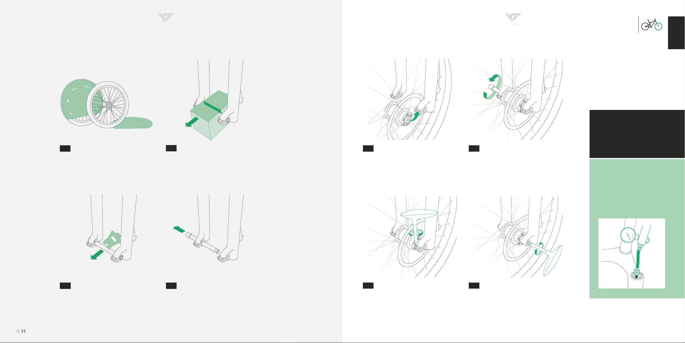
And now you’re ready to ride! Well, almost. First you have to
uncrate this machine, of course. Do it properly and you’ll be
able to use the YT BikeBox again, for transporting your YT or
to send it in for a service. And setting it up? With this manual
easier than you might think.
You’ve guessed it, a manual is just so much more than drifting
on your rear wheel. This one is a step-by-step guide for setting
up and maintaining your ride. For both involve technical knowl-
edge,aswellascraftsmanship.That’swhywe’lltalkyouthrough
all basic settings and maintenance recommendations for your
YT: Follow the instructions and everything will run smoothly.
Needless to say, that this manual is not meant to provide the
knowledge or skills required for professional bike assembly
and it won’t enable you to start building a bike from single
pieces or repairing crucial equipment. But you don’t have to
be MacGyver either.
Together we’ll get the job done!
You don’t feel ready to carry out set-up, maintenance and
repair yourself? No need to break out in cold sweat. Play it safe
and hand the job over to a specialist workshop. Or get in touch
with us: We’ll take care of you. Our service will stand by your
side, answering your questions.
There’s only one thing left to say: This will happen within the
scope of our warranty and liability limitatons and exclusions.
When dealing with inquiries by phone or mail, important details
may be overlooked or get lost in translation. We can never be
100 % sure, that the type and scope of the required work have
been described correctly and to their full extend. Furthermore
there’s always a degree of uncertainty in remote diagnostics
and of course we cannot control whether you have followed
our instructions appropriately. So we hope it’s obvious and
reasonable that we can’t compensate and accept liability for
damages and accidents that are results of self-executed re-
pairs or non-professional maintenance. In either of these cases
warranty of components shall be void. Fair enough, isn’t it?
Get in touch with us! service@yt-industries.com
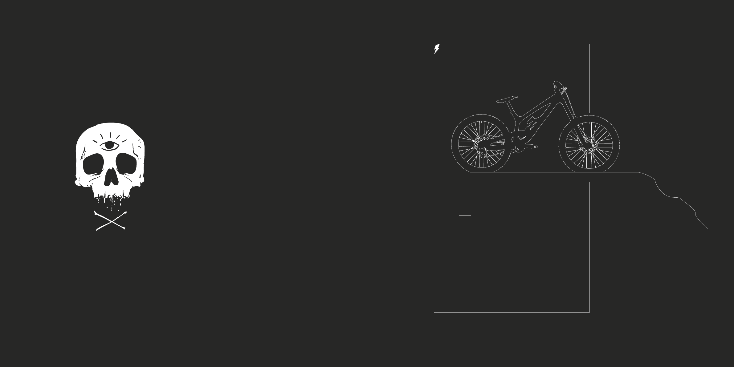
PUT YOUR TRUST IN YT: CHECK.
ORDERED YOUR BIKE: CHECK.
GOOD TIMES: CHECK.
TIP: Don’t ditch the YT BikeBox, keep it, incl. all additional material.
so you can safely repack your bike for transport again.
Good Job.
congrats & thanks for that!

yt 0706 yt
EN
UNBOX YOUR BIKE
Cut the packaging straps using wire cutters
or a box cutter. Just make sure not to dam-
age the YT BikeBox. Now you can pull out
the flaps and open it.
Lift the wheels out of the box. Put the wheels
in a safe place on the side of the box.
Now you can lift your bike upwards, out of
the box.
Place the frame on the front/rear axle stand.
Make sure the bike is standing safely!
HANDLEBAR ASSEMBLY
Cut the zip ties with a wire cutter. Grease the threads of the screws. Mount the
stem base plate on the upper fork crown using
the shorter, rear-side bolts (Allen key 5 mm).
Tighten the bolts. Please follow the torque
specications of the manufacturers
Using the longer bolts, mount the stem
clamps to the upper fork crown through the
holes in the middle of the stem base plate.
Make sure to begin in this order and tighten
the bolts to the specied torque. Also en-
sure that there is no gap between the stem
clamps and the stem base plate in this step
(zero gap).
Now mount the forward bolts of the stem
clamps to the base plate. Pay attention to the
torque recommendations, even clamp gaps,
and the correct alignment of the handlebar.
The adjustment graphics will help you with
this.
RENTHAL FATBAR
1.1
1.4
1.2
1.3
2.1.1
2.1.4
2.1.2
2.1.5 2.1.6
2.1.3

yt 0908 yt
Please follow the
torque specifications of
the manufacturers
EN
Make sure the bike is standing safely on the
rear axle stand.
Turn the rear axle stand on its side. Carefully
cut the cable tie using a wire cutter and re-
move the bubble wrap and the foam transport
protection from the chainstay.
Mount the rear derailleur on the derailleur
hanger (Allen key 5 mm). Please make sure
the bolt is perpendicular to the hanger to avoid
damaging the thread.
REAR DERAILLEUR ASSEMBLY
Tighten the rear derailleur screw using the
torque wrench. Make sure that the rear de-
railleur stop sits at the derailleur hanger stop.
Hold the derailleur with your second hand to
avoid a twisting of the derailleur and a gap.
Remove the stem bolts from the upper fork
crown (Allen key 5 mm)
Put the screws in the stem then place the
handlebar and the stem on the upper fork
crown.
Mount the stem on the upper fork crown
(5 mm Allen key). Tighten the screws in an X
pattern. Do it step by step with just one turn
per screw at a time.This is the only way to
achieve an even clamping of the bolts.
Torque the bolts exactly to the specications
of the manufacturer of the stem and / or han-
dlebar (refer to the black box on the right of
this page). Make sure the gaps in the clamp
are even and that the handlebar is centered
correctly – the adjustment graphics will help
you with this.
2.2.1 2.2.2 2.2.3
2.2.4
RACEFACE ATLAS / CHESTER DIRECT MOUNT
HANDLEBAR ASSEMBLY
3.4
3.1 3.2 3.3

yt 1110 yt
Please follow the
torque specifications of
the manufacturers
EN
Place the rear wheel in the frame. Make sure
to place the chain on the smallest cog of the
cassette. Carefully pull the shifter rearwards
to make the insertion easier.
Guides in the frame will help you align the wheel
properly. Secure the rear wheel with the rear
wheel axle and tighten it using the torque
wrench.
Press the derailleur cage forwards to release
the CAGE LOCK. Once released, carefully
guide the cage rearwards until it puts tension
on the chain.
REAR WHEEL ASSEMBLY
PREPARING
REAR WHEEL ASSEMBLY
Remove the cardboard packaging of both
wheels.
Remove the frame cover from the main frame.
Unscrew the rear wheel axle from the frame
and remove the axle´s transport protection.
Remove the rear axle stand from the rear axle.Open the rear derailleur cage and activate the
CAGE LOCK by pressing the small button with
the lock symbol on it.
Pull the spacer out of the rear brake caliper.
Please keep it for future bike transports.
4.3
4.1
4.4
5.1 5.2 5.34.2
4.5

yt 1312 yt
EN
Unscrew the front wheel axle from the fork
and remove it.
Insert the front wheel in the fork dropouts.
Make sure the brake rotor is centered in the
brake caliper to avoid damages.
FOX: Clamp the front wheel axle in the fork
by tightening the 4 clamping bolts in an al-
ternating pattern, one turn per bolt at a time.
Check the torque of the clamping bolts with
a torque wrench.
Insert the front wheel axle and tighten it. Use
a torque wrench to ensure that the front wheel
is properly secured.
ROCKSHOX: Tighten the non-drive side wedge
expander to the torque specications in the
manual.
FRONT WHEEL ASSEMBLYFRONT WHEEL ASSEMBLY
PREPARING
Remove the front axle stand from the front
wheel axle.
Pull the spacer out of the brake caliper. Please
keep it for future bike transports.
Remove the cardboard packaging of both
wheels.
6.1
Airsprung forks and shocks have
to be lled with the correct air pres-
sure before use! That’s why we have
included a shock pump to your
package: Please read the manu-
facturer manuals to learn how it
works.
Please follow the
torque specifications
of the manufacturers!
6.3 6.4
7.1
7.3.1
7.2
7.3.2
6.2

yt 1514 yt
min 10 cm
mAX 15 cm
Once you have properly adjusted your seat
post height, tighten the seat post clamp with a
torque of 6 – 7 Nm.
10.3
We added a rubber seal to your ToolBox. Slide
it onto the seat post right above the clamp
and tighten the bolt to keep the dirt out.
10.2
EN
The minimum insertion depth of the seat post
is 10 cm. If you insert less, the frame can break
under load. Please also notice the maximum
insertion depth and do not insert the seat
post deeper into the seat tube, otherwise it
may cause damage to the frame in case of
heavy impact.
PEDAL ASSEMBLY INSERTION DEPTH OF THE SEAT POST
Attach the pedals to the cranks using an allen
wrench. Apply some grease to the threads, if
there are washers make sure to use them!
Please note that there’s a right and a left
pedal.
The non-drive side pedal has reverse thread-
ing and is therefore tightened counterclock-
wise.
Unscrew the brake lever clamps (Torx T25) and
remove the attachments of the brake and shift
cables
Swap the brake levers to have the front brake
on your right and the rear brake on your left
side.
Mount the brake levers on your handlebar with
the brake lever clamps. Make sure the clamp
and the break t neatly into another and to
leave no gap (zero gap).
Make sure the levers are correctly aligned and
tighten them with a torque wrench.
BRAKE SWAP
TUES 27 Carbon ( MK3)
S – L: 12 cm
XL – XXL: 14 cm
TUES 27 Aluminum (MK3)
S – XXL: 13 cm
TUES 29 Carbon (MK3)
Regular: 13 cm
Long: 13 cm
X-Long: 16 cm
MAXIMUM
INSERTION DEPTH
OF THE SEAT POST
8.1
8.2
10.19.1
9.3 9.4
9.2

IT´S
DONE before you go out
and ride: here's a few
words on your bike
set-up and maintenance.
yt 1716 yt
EN

yt 1918 yt
EN
WRAP ALL SENSITIVE AREAS WITH
PROTECTIVE MATERIAL. PREVENT
ANY UNWANTED CONTACT BETWEEN
THE FRAME AND THE COMPONENTS,
TO AVOID CAUSING ANY DAMAGE
DURING TRANSPORT.
Unbolt the handlebar from the stem. Slide the
rubber protector over the brake and dropper
post levers and wrap the handlebar in protec-
tive material. Insert the handlebar all the way
into the slot provided in the front axle stand.
Take care not to damage any cables or hoses.
Now install the remaining carton protectors
on the frame.
Place the bike IN the BikeBox on the front
and rear axle stands. Place the wheels in the
slots provided in the bottom of the BikeBox.
The wheel covers should face the frame. Now
secure the wheels, frame, and handlebar with
the Top Box.
Attach the wheel covers on the side of the
brake rotor and then join the two wheels to-
gether with a zip tie. Attach the wheel spacer
to the front wheel with a zip tie (see illustra-
tion).
Attach the foam wrappers to the frame. Se-
cure the chain with a zip tie to avoid damages.
Remove the derailleur from the derailleur
hanger to avoid causing any damage to the
frame. Wrap the derailleur in bubble-wrap and
secure it with a zip tie.
Release all the air from the fork before you
continue. Attach a foam wrapper to the fork
bridge with a zip tie. Also protect the fork legs,
either with carton or foam wrappers.
If this is what it looks like in
your BikeBox, you’ve done it
right. The illustrations show
exactly how all the different
components should be or-
ganized.
Packed like this, your bike
will travel safely and reach
us in good condition.
ALL
BOXED
UP
SHIPMENT / SERVICE SHIPMENT / SERVICE
PACK YOUR BIKE
1. 2. 3.
5. 6.4.

yt 2120 yt
EN
YOU CAN FIND DETAILLED
INFORMATION ABOUT
YOUR BIKE IN YOUR
„SAFETY FIRST.“
HANDBOOK
ADJUSTING THE SUSPENSION ELEMENTS
(REAR SHOCK AND SUSPENSION FORK)
The suspension elements we use allow for a variety
of adjustments. When making adjustments, please
note the detailed instructions of the suspension
element manufacturer. You can find up-to-date
information on their websites:
FOX: http://www.ridefox.com
RockShox: http://www.sram.com/en/rockshox
CAUTION! NEVER OPERATE YOUR BICYCLE
WITH INSUFFICIENT OR EXCESS AIR
PRESSURE! THIS COULD RESULT IN DAMAGE
TO THE FORK OR SHOCKS.
BASIC SETTINGS
The weight of the rider and his position on the bi-
cycle determine the adjustment criteria for the rear
shock and suspension fork. When sitting on the bike,
the suspension will compress to a certain degree –
the so-called ″sag″. Sag should be between 25 – 30 %
for Enduro bikes, between 30 – 40 % for Downhill
bikes, and between 10 – 20 % for Dirt bikes. The ″sag
value″ that corresponds to your riding style is best
determined with a few test rides. Test rides and per-
sonal preferences will also determine the settings of
the compression and rebound speeds of the suspen-
sion elements.
CAUTION! PLEASE NOTE
Your bike’s handling is influenced by each and every
adjustment to the suspension elements – therefore,
please be careful on your rst test rides to avoid
crashes. Avoid any adjustments that could lead to
the suspension elements frequently bottoming out.
They will thank you with a long service life. If you are
uncertain of anything or have any questions, do not
hesitate to contact us at:
GET TO KNOW YOUR BIKE
Familiarize yourself with your new bike. Verify once
again that all screws are tightened to the correct
torque. Our bikes are equipped with modern disc
brake systems with exceptional braking performance.
In addition, the braking performance increases after a
short break-in period. Try to get used to the braking
response and how it differs when riding over various
surfaces. Position the brake levers at your ngertips
so that they can be pulled without excessive effort.
The same applies to the shifters. Shift smoothly and
without applying too much pressure on the pedals.
This will help protect your drive train components.
Please choose a safe and familiar terrain for your ini-
tial test and training rides. You can nd all you need to
know about your bike in our ″SAFETY FIRST.″- manual
as well.
Familiarize yourself with the bike manual before
getting on your bike the rst time.
BEFORE EACH RIDE
By nature, mountain bikes are placed under a lot of
strain. The components of the bike react differently
to stresses, from wear and tear to material fatigue.
Individual components may fail without warning.
Please check your bike regularly for signs of damage
and/or have your bike periodically inspected.
CHECK BEFORE EVERY RIDE
• the seatpost and wheels are rmly secured in
the frame and fork.
•the wheels spin freely.
•the air pressure in the tires, the tension of the
spokes and the hub bearing play.
•the brake function.
•for signs of material fatigue (deformations,
fractures, cracks, signs of impact, etc.).
•all additional components for stability and
operational safety.
•the required torques for all screws.
Do not ride even if only one of the possible defects
is present.
CAUTION! VIBRATIONS THAT OCCUR WHEN
RIDING YOUR MOUNTAIN BIKE CAN LEAD TO
SCREWS LOOSENING (EVEN FOR SCREWS
WITH THREADLOCKER ADHESIVE)!
IN THE EVENT OF A CRASH
Crashes place a lot of strain on your bike’s materi-
al and components. Therefore, before you continue
your ride, check your bike for damage and impaired
functions (see ″Check Before Every Ride″).
Do not continue your ride even if only one of the
possible defects is present. If you are uncertain of
anything or have any questions, do not hesitate to
contact us directly at:
RIDING ON PUBLIC ROADS
IN GERMANY
The German Road Trafc Licensing Regulations
(Straßenverkehrs-Zulassungs-Ordnung, StVZO) dic-
tate the following safety devices when operating
bicycles on public roads:
•A braking and lighting system and a bright
sounding bell.
•Furthermore, every cyclist is obligated to maintain
his vehicle in a roadworthy condition and a state
that is safe for riding.
We would like to explicitly point out that our bikes
are not in compliance with the German road trafc
licensing regulations!
Read more about this topic in the ″SAFETY
FIRST.″-handbook.
OUTSIDE OF GERMANY
Please inquire about the respective regulations for
each country in which you want to ride your YT Bike
on public roads.
DESIGNATED USE
In addition to the assembly instructions, our moun-
tain bikes are also supplied with the operating
instructions from the manufacturers of the indi-
vidual components. You can nd all information
regarding use, maintenance, and care here. Please
follow these instructions and retain them. Damage
that arises from improper or inappropriate use of
your YT are not covered by our warranty.
These include:
•Improper or inadequate maintenance and care.
•Damage from crashes or overstressing.
• Modication to the frame or fork.
• Modication of components.
•Jumps or other stresses that lead to overstraining.
Please refer to our General Terms and Conditions at
www.yt-industries.com.
IMPORTANT GENERAL INFORMATION
We are not liable for property damage or personal
injury resulting from the operation of the mountain
bike itself, in particular, in the event of failures due to
inadequate maintenance and care.
The abilities of professional mountain bikers may
seem easy to imitate to laypersons. In reality, there
are often years of training and constant practice
behind their skills. For your safety, always wear pro-
tective clothing appropriate for the discipline.
We recommend always wearing a protective helmet.
Things always seem to happen when you least
expect them.
CARE AND SERVICE INTERVALS
Only regular inspections, care and maintenance,
immediate professional repair, and the replacement
of damaged components can guarantee the safe
function of your bike over the long term. If you do
not possess the necessary specialist knowledge or
tools to carry out the required work yourself, a trip
to the workshop is essential. For guidance, we have
prepared some maintenance information:
We recommend an initial inspection, depending on
how hard you ride, after 5 to 15 hours of operation.
This includes:
•Checking the torques on all screws and nuts and
tightening them if necessary.
•Changing the length of the shifter cable by
correcting the tension via adjustment (barrel
adjuster on the shifter).
•Checking the spoke tension on the wheels and that
the wheels are true and adjusting spoke tension if
necessary.
•Checking the headset preload and gently readjust
if necessary.
MONTHLY INSPECTIONS
• Checking the prole height and sidewalls of the
tires. Replacing worn or ″washed out″ tires.
•Measuring the strength of the disc brake pads.
Replacing the brake pads if necessary (please note
the manufacturer specications).
•Checking the braking system for leaks. In the event
of leaks, please visit a specialist workshop.
•Checking bearing play in the bottom bracket, head
set, hubs, and pedals and tightening if necessary.
•Checking the spoke tension on the wheels and that
the wheels are true and adjusting spoke tension if
necessary.
•Checking the torques on screws and nuts. If neces
sary, tightening screws and nuts.
•Cleaning and greasing the drivetrain and derailleur
mechanism.
ANNUAL INSPECTIONS
•Suspension fork service: Please note the
specications of the manufacturer here.
•Remove the bottom bracket, clean it, and regrease
the treads.
•Remove the headset, check the bearings and
regrease them.
•Remove the stem, handlebar, and seatpost and
check them for cracks and damage and replace
them if necessary.
•Check the shifter cable for damage (breaks, kinks,
corrosion, etc.) and exchange them if necessary.
ADJUSTMENTS ADJUSTMENTS
AFTER ASSEMBLY AFTER ASSEMBLY

yt 2322 yt
EN
BIKE FRAMES MADE FROM CARBON (CFRP)
HANDLING AND USE
IF NO WHEEL
INSTALLED KEEP
REAR WHEEL
AXLE LOOSE!
CONTACT YT IMMEDIATELY
AFTER YOU HAD A CRASH!
SERVICE@YT-INDUSTRIES.COM
USE TRANSPORT
LOCK!
CHECK PROTECTIVE
FOILS REGULARLY!
TO AVOID DAMAGE TO PERSONS AND
PROPERTY WE ASK YOU TO FOLLOW THESE
INSTRUCTIONS
The use of carbon (carbon ber reinforced plastic /
CFRP) makes it possible for us to produce high-per-
formance products for our customers. Since these
components and frame elements can be sensitive
and delicate under certain conditions, there is a risk
of breaks which could lead to accidents and property
damage in the event of improper use, assembly er-
rors or poor maintenance and care. That is why being
knowledgeable about this material is important for
enjoying a carbon frame in the long term.
When these products are overstressed, no last-
ing deformations are visible even though the inner
structure could be damaged. In addition, rock im-
pacts or messy falls involving impacts on edges
can result in invisible damages and/or delamination
(= carbon layers dissolve) of the carbon material.
For these reasons, an element or frame made of
CFRP can fail without perceptible warning.
Pay attention if your carbon frame makes unusual
cracking noises. This could be a sign of an impen-
ding material defect. If this occurs, STOP using the
bike immediately and turn to YT.
IF THE FOLLOWING OCCURS, IT IS
ABSOLUTELY ESSENTIAL TO HAVE THE
FRAME INSPECTED BY YT INDUSTRIES
•after a crash
•after major mechanical stresses
•Unusual noises from the frame (e.g. snapping
sounds)
INFORMATION ON FRAME CONSTRUCTION
The manufacture of these high-end products is
done by hand. This can lead to differences in the
nish which are not cause for complaint.
HOW TO CORRECTLY HANDLE
YOUR CARBON FRAME
General information
•Under no circumstances should you install rings,
screw connections, clamps or other elements
which exert mechanical forces on the carbon tube.
•Never clamp the carbon tube or carbon seat post
of your bike on the gripping jaws of a work stand
or bike rack.
•Be careful when using U-locks – under certain
circumstances, they can cause damage to your
frame.
Seat clamp / seat post
•The prescribed tightening torque of the seat
clamp bolt is 5 Nm.
•The seat post must not be rubbed out or other
wise mechanically stressed.
•The seat post and seat tube may not be
lubricated. Only carbon assembly paste can be
used.
•Aluminum seat posts may only be installed when
carbon assembly paste is used.
•The seat clamp must not be closed when the seat
post has been removed. Risk of fracture!
Carbon Handlebar
Installing carbon handlebars requires great care and
precision. Do not exceed the specied torque under
any circumstances and make sure that the stem
does not have any sharp edges or ridges.
•Please note the prescribed tightening torque of
the stem manufacturer.
•Carbon handlebars can only be installed using
carbon assembly paste.
•If you would like to shorten the handlebar, note
the specications of the manufacturer or contact
us directly.
Rear wheel axle
•To prevent damages to the seat stays, the rear
wheel axle must never be completely closed if the
wheel is not in the frame.
Transport
You must be particularly careful when transporting
bikes with carbon frames:
•Protect the frame in particular from contact with
other parts (use covers, etc.).
• Do not use transport ttings which use clamping
elements. Clamping forces could damage the
frame structure.
•Do not place any objects on the frame.
•Make sure the bike cannot slide around during
transport.
•Never transport without rear wheel or rear section
transport lock assembled.
CARE INFORMATION
Your carbon frame needs regular care. Common
paint care products with or without silicon additives
and cold to lukewarm water are suitable for cleaning.
You can add common dish detergents to the cold to
lukewarm water.
All solvents must be avoided:
•alcohols (e.g. ethanol or isopropanol)
•hot water with alkaline additives
•do not clean with steam jets or high-pressure
cleaners
Check whether your frame has external damage at
regular intervals (e. g. during maintenance):
•cracks
•paint damages
• discoloration
•deformation (bulges, etc.)
SURFACE PROTECTION
YT Industries carbon frames are equipped with
protective foils or protectors made of polyamide or
polyurethane at points which are exposed to particu-
lar stress.
Other points could form due to different application
areas and conditions (e.g. wearing knee protectors).
These areas must be protected against damage or
abrasions with additional protective foils.
•Please check at regular intervals whether the
protective foils are still functional.
•We recommend replacing the protective foil around
tension points once a year.

yt 2524 yt
REAR TRIANGLE
ASSEMBLY & DISASSEMBLY
YOU CAN FIND A DETAILLED
STEP-BY-STEP INSTRUCTION
ON OUR WEBSITE!
WARNING: IF YOU DO NOT
MOUNT THE AXLE IN THE COR-
RECT WAY, YOU RUN THE RISK
OF DAMAGING YOUR FRAME
WHILE RIDING. IF YOU ARE NOT
SURE, LEAVE THE ASSEMBLY TO
A QUALIFIED SPECIALIST WORK-
SHOP.
IN THE REAR TRIANGLE OF THE
TUES YOU WILL FIND THREE
AXLES THAT ARE MOUNTED WITH
A SPREADER CONE, THESE ARE
MARKED IN THE DRAWING.
To assemble these axles, you rst screw
in the axle itself, followed by the expan-
sion cone.
grease
grease
grease
grease
grease
grease
grease
grease
grease
12 nm Loctite
12 nm Loctite
12 nm Loctite
8 nm Loctite
17 nm
15 nm
20 nm
5 nm Loctite
5 nm Loctite
Loctite
grease
Loctite
EN

yt 2726 yt
DE
Und jetzt: ready to ride! Naja, fast. Vorher musst Du Dein
Bike natürlich noch auspacken. Mach es so, dass Du die YT
BikeBox danach nochmal verwenden kannst. Und der Aufbau?
Mit diesem Manual weniger kompliziert als Du denkst!
Ein Manual ist mehr als auf dem Hinterrad zu surfen. In diesem
hier zeigen wir Dir – Schritt für Schritt – die richtige Technik für
Aufbau und Wartung Deines Bikes. Denn beides erfordert
technisches Wissen und handwerkliches Geschick. Darum
beschreiben wir hier alle grundlegenden Einstellungen und
Wartungsempfehlungen für Dein YT: Wenn Du den einzelnen
Anweisungen folgst, wird alles glatt gehen. Natürlich kann
diese Anleitung eine Fachausbildung im Fahrradhandwerk
nicht ersetzen; und auf keinen Fall kannst Du mit ihr ein Bike
aus Einzelteilen zusammenbauen. Du musst aber auch nicht
MacGyver sein.
Wir machen das zusammen!
Aufbau, Wartung und Reparaturen fachgerecht durchzu-
führen bekommst Du trotzdem nicht auf die Kette? Kein Grund
zu verzweifeln! Bieg in einer Fachwerkstatt ab und lass die
Andern machen. Oder melde Dich einfach bei uns: Wir helfen
Dir weiter.
Unser Service wird Dir bei Deinen Fragen zur Seite stehen.
Eines sei jedoch gesagt: Das Ganze passiert im Rahmen un-
serer Gewährleistungs- und Haftungsausschlüsse. Bei tele-
fonischen oder schriftlichen Nachfragen können wichtige
Details nämlich auch mal auf der Strecke bleiben: Wir kön-
nen nie 100%ig sicher sein, dass Art und der Umfang der an-
fallenden Arbeiten vollständig und richtig beschrieben werden.
Ferndiagnosen unterliegen deshalb immer einer gewissen
Unsicherheit und genauso können wir natürlich auch nicht
überprüfen, inwieweit unsere Arbeitsanweisungen von Dir
richtig und vollständig umgesetzt wurden.
Klar, dass wir für Schäden oder Unfälle, die auf nicht fach-
gerechte Wartung oder selbst durchgeführte Reparaturen zu-
rückgehen, keine Haftung übernehmen können. Verstehste, ne?
Du erreichst uns über: service@yt-industries.com
YT VERTRAUT.
BIKE BESTELLT.
GOOD TIMES GEBUCHT.
TIPP: Hebe die YT BikeBox inklusive Aller Verpackungsmaterialien
auf. So kannst du dein Bike für einen Transport wieder verpacken.
Alles richtig gemacht:
Glückwunsch & danke dafür!

yt 2928 yt
DE
BIKE AUSPACKEN
Durchtrenne die Verpackungsbänder mit ei-
nem Seitenschneider oder Cutter. Pass auf,
dass Du die BikeBox dabei nicht beschädigst.
Jetzt kannst Du die Verschlusslaschen her-
ausziehen und die BikeBox öffnen.
Hebe die Laufräder nach oben aus dem
Karton heraus. Stelle die Laufräder dann auf
die Seite, an einen sicheren Platz.
Jetzt kannst Du Dein Bike nach oben aus der
BikeBox ziehen.
Stelle den Rahmen auf dem Front- / Rear-Axle-
Stand ab. Achte auf einen sicheren Stand des
Bikes!
RENTHAL FATBAR
LENKERMONTAGE
Entferne die Kabelbinder am Lenker mit
einem Seitenschneider und löse die Lenker-
klemmung.
Fette die Schraubengewinde und montiere
die Grundplatte des Vorbaus mit den
hinteren, kurzen Schrauben auf der Gabel-
brücke (Inbus 5 mm).
Ziehe die Schrauben mit dem entsprechen-
den Drehmoment an. Halte bei der Montage
bitte die Drehmomentangaben der Herstel-
ler ein.
Schraube mit den langen Schrauben die
Lenkerklemmung durch die mittigen Löcher
der Grundplatte hindurch auf die Gabel-
brücke.
Beginne unbedingt in dieser Reihenfolge
und achte beim Anziehen auf das korrekte
Drehmoment. Achte darauf, dass kein Spalt
entsteht (zero gap).
Befestige die vorderen Schrauben der Lenker-
klemmung an der Grundplatte des Vorbaus.
Achte auf das richtige Drehmoment, einen
gleichmäßigen Klemmspalt und auf den
genauen, mittigen Einbau des Lenkers. Die
Einstelllinien helfen Dir dabei.
2.1.1
2.1.4
2.1.2
2.1.5 2.1.6
2.1.3
1.1
1.4
1.2
1.3

yt 3130 yt
Halte bei der Montage
bitte die Drehmoment-
angaben der
Hersteller ein
DE
Achte darauf, dass Dein Bike sicher auf dem
Rear-Axle-Stand steht.
Drehe den Rear-Axle-Stand auf die Seiten-
fläche. Entferne den Kabelbinder mit dem
Seitenschneider und ziehe die Luftpolsterfolie
sowie den Schaumstoff-Transportschutz ab.
Befestige das Schaltwerk am Schaltauge
(Inbus 5 mm).
SCHALTWERKMONTAGE
Ziehe die Schraube des Schaltwerks mithilfe
des Drehmoment-Schlüssels an. Achte
darauf, dass der Anschlag des Schaltwerks
auf dem Anschlag des Schaltauges liegt.
Halte das Schaltwerk mit der anderen Hand
fest, um ein Verdrehen zu verhindern und
damit kein Spalt entsteht.
Entferne die Schrauben des Vorbaus von der
oberen Gabelbrücke (Inbus 5 mm).
Setze die Schrauben im Vorbau ein. An-
schließend platzierst Du Lenker und Vorbau
auf der Gabelbrücke.
Montiere den Vorbau auf der Gabelbrücke (In-
bus 5 mm). Ziehe die Schrauben schrittweise
mit jeweils nur einer Umdrehung über Kreuz
an. Nur so erreichst Du eine gleichmäßige
Klemmung.
LENKERMONTAGE
RACEFACE ATLAS / CHESTER DIRECT MOUNT
Das Drehmoment der Schrauben sollte
genau den Herstellerrichtlinien des Vor-
baus und / oder Lenkers entsprechen (siehe
schwarzes Feld rechts). Achte auf einen
gleichmäßigen Klemmspalt und auf den
genauen, mittigen Einbau des Lenkers. Die
Einstelllinien helfen Dir dabei.
2.2.1 2.2.2 2.2.3
2.2.4 3.4
3.1 3.2 3.3

yt 3332 yt
Halte bei der Montage
bitte die Drehmoment-
angaben der
Hersteller ein
DE
Drücke das Schaltwerk nach hinten weg und
setze das Hinterrad in den Rahmen. Einführ-
hilfen im Rahmen erleichtern die korrekte
Positionierung. Achte darauf, die Kette auf
das kleinste Ritzel der Kassette zu legen.
Einführhilfen im Rahmen erleichtern die kor-
rekte Positionierung des Hinterrads. Sichere
das Hinterrad mit der Hinterradachse und
verschraube es mithilfe des Drehmoment-
schlüssels.
Drücke den Käfig des Schaltwerks nach
vorne, bis der CAGE LOCK entriegelt. Führe
das Schaltwerk anschließend vorsichtig nach
hinten, bis die Kette gespannt ist.
HINTERRADEINBAU
VORBEREITUNG
HINTERRADEINBAU
Entferne die Versandverpackung der beiden
Laufräder.
Entferne das Frame Cover vom Hauptrahmen
und ziehe den Rear-Axle-Stand von der Hinter-
achse.
Ziehe die Transportsicherung aus dem Sattel
der Hinterradbremse. Hebe sie für einen
erneuten Transport des Bikes auf.
Ziehe den Käg des Schaltwerks nach vorne
und drücke anschließend auf den Verriege-
lungsknopf (Schloss-Symbol), um den CAGE
LOCK zu aktivieren.
Schraube die Hinterradachse aus dem Rah-
men und entferne den Transportschutz von
der Achse.
4.3
4.1
4.4
5.1 5.2 5.34.2
4.5

yt 3534 yt
DE
Schraube die Vorderradachse aus der Feder-
gabel und ziehe sie heraus.
Setze das Vorderrad in die Federgabel ein.
Achte darauf, die Bremsscheibe vorsichtig
in den Bremssattel zu schieben, um eine
Beschädigung zu verhindern.
Setze die Vorderradachse ein und ver-
schraube sie. Benutze einen Drehmoment-
schlüssel, um den korrekten Sitz der Vorder-
radachse zu gewährleisten.
VORDERRADEINBAUVORDERRADEINBAU
VORBEREITUNG
Entferne den Front-Axle-Stand von der Vor-
derradachse.
Ziehe die Transportsicherung aus dem Sattel
der Vorderradbremse. Hebe sie für einen
erneuten Transport Deines Bikes auf.
Entferne die Versandverpackung der beiden
Laufräder.
6.1
FOX: Verklemme die Vorderradachse
in der Gabel, indem Du die vier Klemm-
schrauben im Wechsel mit jeweils nur einer
Umdrehung kreuzweise anziehst. Kontrolliere
anschließend mit dem Drehmomentschlüssel
den Sitz der Schrauben.
ROCKSHOX: Ziehe den Klemmkonus auf der
Nicht-Antriebsseite entsprechend der Herstel-
lerangaben fest.
Luftgefederte Gabeln und Dämpfer
müssen vor dem Gebrauch un-
bedingt mit dem korrekten Luft-
druck befüllt werden. Dazu haben
wir Deinem YT eine Dämpfer-
pumpe beigelegt. Wie’s geht,
erfährst Du in den beigelegten
Hersteller-Manuals.
Halte bei der Montage
bitte die Drehmoment-
angaben der
Hersteller ein
7.3.1 7.3.2
6.3 6.4
7.1 7.2
6.2

yt 3736 yt
min 10 cm
mAX 15 cm
Die Mindesttiefe, um die Du die Stütze
versenken musst, beträgt 10 cm. Wenn Du
sie weiter herausziehst, kann der Rahmen bei
Belastung brechen. Bitte beachte auch die
maximale Versenktiefe und versenke die Stütze
nicht tiefer im Sitzrohr, sonst besteht die
Gefahr, dass sie bei einem heftigen Einschlag
im Rahmeninneren Schäden verursacht.
EINBAUTIEFE SATTELSTÜTZE
Sichere die eingestellte Sattelstützenhöhe,
indem Du die Schraube der Sattelklemme auf
6 – 7 Nm festziehst.
TUES 27 Carbon ( MK3)
S – L: 12 cm
XL – XXL: 14 cm
TUES 27 Aluminium (MK3)
S – XXL: 13 cm
TUES 29 Carbon (MK3)
Regular: 13 cm
Long: 13 cm
X-Long: 16 cm
MAXIMALE
VERSENKTIEFE
SATTELSTÜTZE
10.1
10.3
In der ToolBox ndest Du eine Gummidich-
tung für die Sattelstütze. Stülpe sie über die
Sattelstütze und montiere sie oberhalb der
Klemme, um das Eindringen von Schmutz zu
verhindern.
10.2
DE
PEDALMONTAGE
Verschraube die Pedale mit einem Inbus-
schlüssel in der Kurbel. Fette die Gewinde
der Pedale, um eine perfekte Funktion zu ge-
währleisten. Achte darauf, dass es ein linkes
und ein rechtes Pedal gibt.
Das Pedal auf der Nicht-Antriebsseite hat ein
Linksgewinde und wird gegen den Uhrzeiger-
sinn zugezogen.
BREMSEN TAUSCHEN
Löse die Verschraubung der Bremsen an der
Schelle (Torx T25). Entferne die Befestigung
der Brems- und Schaltleitungen.
Vertausche die Bremsgriffe so, dass die Vor-
derradbremse auf der rechten Seite und die
Hinterradbremse auf der linken Seite ist.
Befestige die Bremsgriffe mithilfe der Schel-
len am Lenker. Achtung! Allgemein – aber
ganz besonders bei Carbonlenkern – ist es
wichtig, dass Bremse und Schelle formschlüs-
sig ineinandergreifen und kein Spalt entsteht
(zero gap).
Achte auf die korrekte Ausrichtung der
Bremsgriffe und ziehe sie auf das vorge-
schriebene Drehmoment fest.
8.1
8.2
9.1
9.3 9.4
9.2

IT´S
DONE bevor es losgeht,
gibt's hier noch Infos
zur Einstellung und
pflege deines Bikes.
yt 3938 yt
DE
Table of contents
Languages:
Other YT Industries Bicycle manuals

YT Industries
YT Industries Jeffsy Primus User manual

YT Industries
YT Industries rtfm. User manual

YT Industries
YT Industries TUES FR User manual

YT Industries
YT Industries Jeffsy User manual

YT Industries
YT Industries RTFM JEFFSY Instruction sheet

YT Industries
YT Industries Capra MX CORE 3 Instruction sheet

YT Industries
YT Industries DIRTLOVE User manual

YT Industries
YT Industries TUES MKIII User manual

YT Industries
YT Industries TUES 27 Carbon User manual