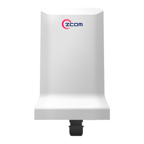
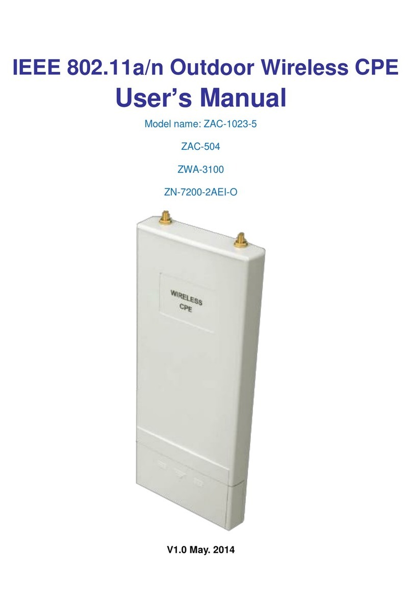
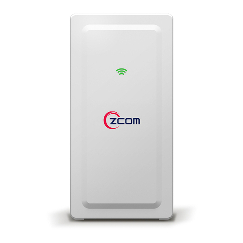
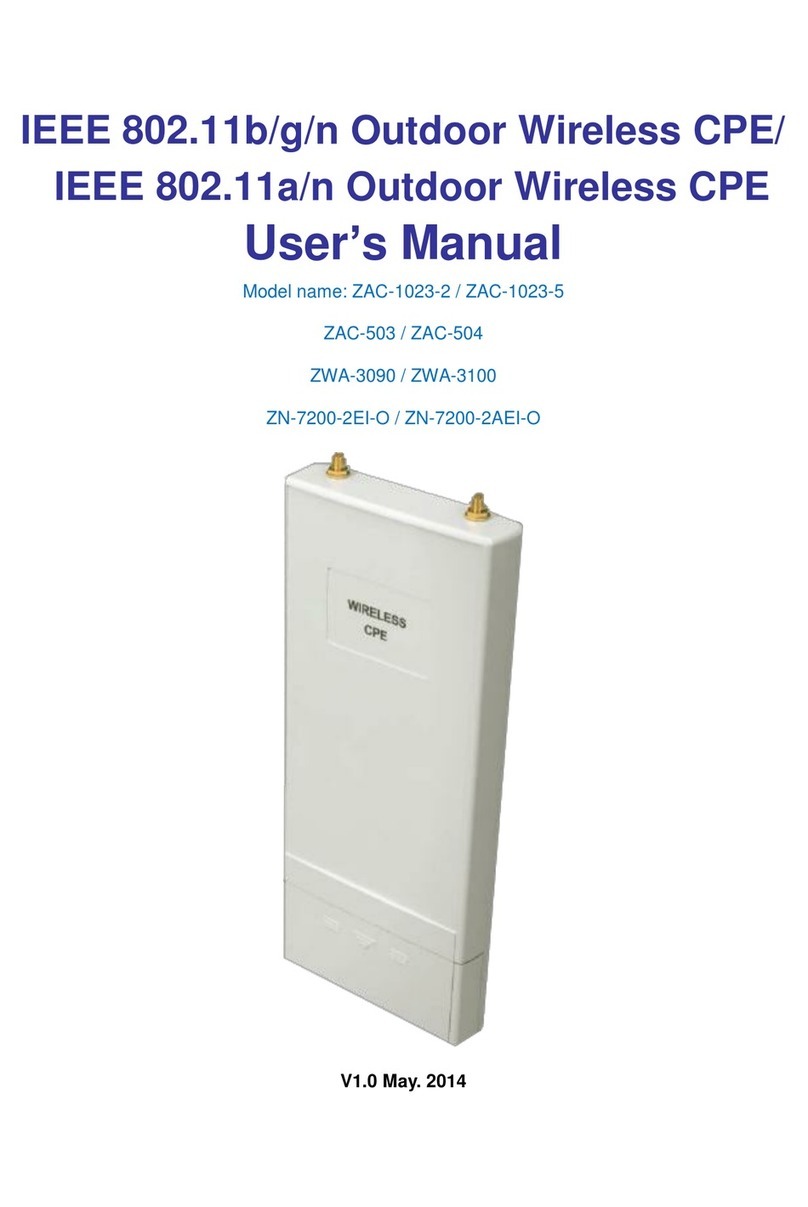
Zcom SP230 Series User manual

SP230/SP230-S5 2x2 PtP/PtMP 802.11ac Wave 2 Outdoor Access Point User Manual
Page 1

SP230/SP230-S5 2x2 PtP/PtMP 802.11ac Wave 2 Outdoor Access Point User Manual
Page 2
TABLE OF CONTENTS
Chapter 1. Introduction ......................................................................................................................................................... 4
Product Description .........................................................................................................................................................................................41.1.
Chapter 2. Hardware Features .............................................................................................................................................. 5
Package Contents .............................................................................................................................................................................................52.1.
Installation Requirements ..............................................................................................................................................................................52.2.
Physical Ports ......................................................................................................................................................................................................62.3.
LED Indicator.......................................................................................................................................................................................................62.4.
Chapter 3. Hardware Installation ......................................................................................................................................... 7
Mounting the Access Point on the Pole...................................................................................................................................................73.1.
Two-dimensional Mounting Kit (Optional accessory_SP-MKM5)..................................................................................................73.2.
Pole-Mount..............................................................................................................................................................................................73.2.1.
Wall-Mount..............................................................................................................................................................................................83.2.2.
Anti-theft Steel Rope (Optional accessory_SP-CBM5) .......................................................................................................................93.3.
Grounding Connection & Protect from Lightning...............................................................................................................................93.4.
Safety Notice.......................................................................................................................................................................................................93.5.
Installing a Waterproof Cable Gland for Ethernet Port (Optional accessory_ SP-WP-CM20) ......................................... 103.6.
Powering the Access Point ......................................................................................................................................................................... 103.7.
Chapter 4. The HTTP Interface ...........................................................................................................................................11
Login to the HTTP Interface ....................................................................................................................................................................... 114.1.
Thin AP (TAP) Mode...................................................................................................................................................................................... 114.2.
Access Point Configuration ............................................................................................................................................................ 114.2.1.
Status ...................................................................................................................................................................................................... 134.2.2.
4.2.2.1. Overview...................................................................................................................................................................................... 13
4.2.2.2. General ......................................................................................................................................................................................... 13
4.2.2.3. System Log ................................................................................................................................................................................. 14
System .................................................................................................................................................................................................... 144.2.3.
4.2.3.1. AP Mode...................................................................................................................................................................................... 14
4.2.3.2. Reboot.......................................................................................................................................................................................... 15
Fat AP (FAP) Mode......................................................................................................................................................................................... 154.3.
Status ...................................................................................................................................................................................................... 154.3.1.
4.3.1.1. Overview...................................................................................................................................................................................... 15
4.3.1.2. Firewall.......................................................................................................................................................................................... 16
4.3.1.3. Routes........................................................................................................................................................................................... 16
4.3.1.4. System Log ................................................................................................................................................................................. 17

SP230/SP230-S5 2x2 PtP/PtMP 802.11ac Wave 2 Outdoor Access Point User Manual
Page 3
4.3.1.5. Kernel Log ................................................................................................................................................................................... 17
4.3.1.6. Real-time Graphs...................................................................................................................................................................... 17
System .................................................................................................................................................................................................... 194.3.2.
4.3.2.1. System .......................................................................................................................................................................................... 19
4.3.2.2. Administration........................................................................................................................................................................... 19
4.3.2.3. Scheduled Tasks ....................................................................................................................................................................... 19
4.3.2.4. Backup / Flash Firmware ....................................................................................................................................................... 20
Network.................................................................................................................................................................................................. 214.3.3.
4.3.3.1. Interfaces ..................................................................................................................................................................................... 21
4.3.3.2. Wifi................................................................................................................................................................................................. 49
4.3.3.3. DHCP and DNS ......................................................................................................................................................................... 61
4.3.3.4. Static Routes .............................................................................................................................................................................. 65
4.3.3.5. Diagnostics ................................................................................................................................................................................. 66
4.3.3.6. Firewall.......................................................................................................................................................................................... 68
4.3.3.7. Bluetooth..................................................................................................................................................................................... 71
4.3.3.8. Externalvlan ................................................................................................................................................................................ 71
Bridge Mode .................................................................................................................................................................................................... 714.4.
Adjust the time zone......................................................................................................................................................................... 714.4.1.
AP General Setup ............................................................................................................................................................................... 724.4.2.
Bridge Mode Setup ........................................................................................................................................................................... 724.4.3.
VLAN Trunk........................................................................................................................................................................................... 754.4.4.
Chapter 5. Technical Specifications ...................................................................................................................................76
Chapter 6. Appendix ............................................................................................................................................................78
Warranty ............................................................................................................................................................................................................ 786.1.
General Warranty ............................................................................................................................................................................... 786.1.1.
Warranty Conditions......................................................................................................................................................................... 786.1.2.
Disclaimer.............................................................................................................................................................................................. 786.1.3.
Compliance Information.............................................................................................................................................................................. 796.2.
RF Exposure Warning........................................................................................................................................................................ 796.2.1.
CE Marking............................................................................................................................................................................................ 796.2.2.
RoHS/WEEE Compliance Statement........................................................................................................................................... 796.2.3.
Declaration of Conformity .......................................................................................................................................................................... 796.3.
Optional Accessories..................................................................................................................................................................................... 806.4.
Contact Information...................................................................................................................................................................................... 806.5.
SP230/SP230-S5 2x2 PtP/PtMP 802.11ac Wave 2 Outdoor Access Point User Manual
Page 4
Chapter 1. INTRODUCTION
This manual is intended for installing and managing the SP230 Series using the HTTP interface. The
SP230 series will simply be referred to as the AP (Access Point) within this guide. The installer
should be familiar with network structures, terms, and concepts.
Product Description1.1.
The SP230 Series is a dual-band (2x2) Wave 2 outdoor AP that supports the IEEE 802.11ac standard
and can provide wireless data rates up to 1.1 Gbps using MU-MIMO technology and optimizing
the 2.4 GHz and 5 GHz frequency bands. The 2.4GHz and 5GHz radios can be used for client access,
backhaul traffic, or both. Products details are available on Z-COM website at
https://www.zcom.com.tw/index/product/details?id=29
The access point can also operate as a relay mode for other access points that are not directly
connected to a wired network. This enables each access point to identify neighbors and
intelligently choose the optimal path to the wired network by calculating the cost of each path in
terms of signal strength and the number of hops required to get to a controller.
The access point can be configured, monitored, and operated through a Z-COM wireless LAN
controller. The controllers use a browser-based management system to manage the controller and
the associated access points.
The model numbers and configuration for the Z-COM SP230 Series outdoor access points are
described here:
Standards
IEEE 802.11a/b/g/n/ac
Radio Chains
2.4GHz: 2x2:2; 5GHz: 2x2:2
Antenna
Peak Gain
SP230
SP230-S5
2.4GHz: 5dBi (Embedded)
5GHz: 5dBi (Embedded)
2.4GHz: 5dBi (Embedded)
5GHz: 11dBi (Embedded)
Antenna Type 2.4/5GHz: Omni antenna
2.4GHz: Omni antenna
5GHz: Directional antenna
Interface
2 x 1GbE RJ45 port

SP230/SP230-S5 2x2 PtP/PtMP 802.11ac Wave 2 Outdoor Access Point User Manual
Page 5
Chapter 2. HARDWARE FEATURES
Package Contents2.1.
Carefully remove all the items from the packing of AP. The following items should be included in
the packaging:
One outdoor access point
One clamp
Two waterproof cable glands
One ground wire
One mounting bracket
+ Four screws
Note: SP230 and SP230-S5 both provides two waterproof cable glands.
Installation Requirements2.2.
TERMS OF USE: All Ethernet cabling runs must use CAT5e, 24 AWG (or above) Shielded Twisted
Pair (STP) cabling. In addition, please cut the cable into a proper length, strip the cables on both
ends, and crimp the wires into RJ45 connectors. It is the professional installer’s responsibility to
follow local country regulations, including operation within legal frequency channels, output power,
indoor cabling requirements, and Dynamic Frequency Selection (DFS) requirements.

SP230/SP230-S5 2x2 PtP/PtMP 802.11ac Wave 2 Outdoor Access Point User Manual
Page 6
Physical Ports2.3.
The following physical ports are available on the SP230/SP230-S5.
The following table describes the physical ports that are available on the AP from left to right.
Port
Description
WAN/PoE Port
The WAN/PoE port operates at 10/100/1000 Mbps supports an RJ45
connection. Supporting PoE In, the AP can receive power through the WAN
port from PSE (Power Sourcing Equipment), rendering the need for a power
supply into the power port.
LAN Port
The LAN port operates at 10/100/1000 Mbps at supports an RJ45 connector.
Supporting PoE Out, the LAN port can supply PoE power to PDs (Powered
Devices) plugged into the LAN port. Up to 10 Watts output power can be
supplied.
Grounding Access point that can't find its way to local earth ground will transfer to the
interior equipment over the communication and power cable.
LED Indicator2.4.
The following table describes the AP status referring to different LED behavior.
Color
Behavior
Description
Red
Steady
Initializing
Flashing
Power / system on
Green
Steady
Internet connection detected
Flashing
No internet connection detected

SP230/SP230-S5 2x2 PtP/PtMP 802.11ac Wave 2 Outdoor Access Point User Manual
Page 7
Chapter 3. HARDWARE INSTALLATION
Mounting the Access Point on the Pole3.1.
Attach the mounting bracket to the AP using
four screws (included in the packaging).
Securely tighten the screws.
Attach the clamp to encircle pole and the
mounting bracket. Securely tighten the clamp.
Note: Please avoid having obstacles or metal plates surround the access point.
Two-dimensional Mounting Kit (Optional accessory_SP-3.2.
MKM5)
Pole-Mount3.2.1.
Attach the intermediate steel plate to the
device using four M5 screws (included in the
packaging). Securely tighten the screws.
Attach the two-dimensional mounting
bracket to the intermediate steel plate using
four M4 screws (included in the packaging).
Securely tighten the screws.
Attach the pole-supported bracket and align the area where the flat head screws will be
attached. Insert two flat head screws into two-dimensional mounting bracket, and tighten
them approximately.

SP230/SP230-S5 2x2 PtP/PtMP 802.11ac Wave 2 Outdoor Access Point User Manual
Page 8
Note: The pole-supported bracket can accommodate up to 6 cm (2.36”) in diameter.
Wall-Mount3.2.2.
Separate it into two parts: half-mounting
bracket and M-type bracket and unscrew
four hex head machine bolts on the two-
dimensional mounting bracket.
Attach the intermediate steel plate to the
device using four M5 screws (included in
the packaging). Securely tighten the screws.
Attach half-mounting bracket to the device
with intermediate steel plate using four M4
screws (included in the packaging).
Securely tighten the screws.
Attach M-type bracket to the device onto
the wall, using four M5 screws + screw
anchors (included in the packaging).
Securely tighten the screws.
Attach half-mounting bracket to the M-type bracket, then screw four hex head machine bolts.
Securely tighten the screws.

SP230/SP230-S5 2x2 PtP/PtMP 802.11ac Wave 2 Outdoor Access Point User Manual
Page 9
Anti-theft Steel Rope (Optional accessory_SP-CBM5)3.3.
Insert three of anti-theft screws (included
in the packaging) to the device through
the mounting bracket. Securely tighten
these three screws.
Encircle the anti-theft steel rope around the pole,
and insert the last anti-theft screw (included in the
packaging) to the device with one side of anti-theft
steel rope. Securely tighten the screw.
Grounding Connection & Protect from Lightning3.4.
1. Make your device GND port connect to ground wire.
2. The ground wire connects to the earth. In addition, the
grounding wire meets to 6-AWG copper grounding wire.
Safety Notice3.5.
1. Do not install the device close to any electrical grounding device or lightning protection
system. Place the device’s own grounding and lightning protection system apart from any
electrical grounding device and lightning protection system as far as possible.
Note: Be sure that grounding is available and that it
must comply with local and national electrical codes.
For additional lightning protection, use lightning rods
and lightning arrestors.

SP230/SP230-S5 2x2 PtP/PtMP 802.11ac Wave 2 Outdoor Access Point User Manual
Page 10
2. Protect components from electrostatic discharge: Please wear an ESD wrist strap or handle the
power adapter by its edge and do not touch any component or printed circuit boards,
especially for module device.
3. Make sure to keep the temperature and humidity of the installation location at an optimal
level.
4. An excellent grounding system guarantees the stable operation of device, as well as to protect
device from lightning, interference and electrostatic discharges.
5. If installed outdoors, the device may be damaged by lightning. We recommend that you install
additional lightning protection devices if necessary, considering the conditions in your area.
6. Supply stable power to the device. Unstable power may cause the device to malfunction. The
device supports PoE power supply and is recommended if the device is installed near grid lines
within less than 100 meters radius.
Installing a Waterproof Cable Gland for Ethernet3.6.
Port (Optional accessory_ SP-WP-CM20)
Dismantle all the components of waterproof cable gland, and plug the cable
through it. Thread and assemble one by one: sealing nut, plastic ring, rubber,
finally is locking nut. Securely tighten all the components.
Powering the Access Point3.7.
Connect the PoE cable into the WAN/PoE IN port of the device, then it will power on.
Warning: Do NOT attempt to connect any non-PoE devices to LAN port and make sure
the input power should comply with PoE Out standard.
Note: Please wait for 5-10 seconds while powering on.
Note: For PoE Out applications, the LAN port provides DC 48V, Max. 208mA, and up to
10W power supply. The positive side of the 48V is connected to pin 4 and 5, the negative
side is connected to pin 7 and 8.

SP230/SP230-S5 2x2 PtP/PtMP 802.11ac Wave 2 Outdoor Access Point User Manual
Page 11
Chapter 4. THE HTTP INTERFACE
The AP can be configured through its supported software interface HTTP. The HTTP interface can
be accessed using any standard web browsing software through any network. This chapter
explains all the elements that are available on the HTTP interface of the AP.
Note: The default Username is root and Password is password.
Note: Click the icon to add a new entry. Click the icon to remove an entry.
Note: Click Reset button to return the parameters on the page to their previously
saved state.
Note: Click Save button to accept and save the modifications made on the page.
Note: Click Save & Apply button to save and apply the modifications made
on the page.
Login to the HTTP Interface4.1.
To access the HTTP interface on the AP, enter the IP address of the AP into the web browser’s
address bar and press the Enter key.
Enter the Username and Password in the respective textboxes and click the Login button. To
return the information, displayed in the textboxes to the defaults, click the Reset button.
In a default access point configuration, the SP230 default AP mode is TAP mode, and SP230-S5
is FAP mode.
Thin AP (TAP) Mode4.2.
The procedure for completing the access point’s essential configuration depends on whether you
want it to be managed by wireless LAN controllers (WLC).
To configure the access point to be managed by the WLC, you must ensure that the APs will be
able to locate and connect to the WLC when powered on. When connected to the network, each
AP is assigned a valid IP address.
Access Point Configuration4.2.1.
Note: In TAP mode, the AP must be able to go with wireless LAN controllers (WLCs) for
bulk configuration and performing other commands of access points. Please refer to WLC
QSG for settings first, then go back to finish the AP configuration.

SP230/SP230-S5 2x2 PtP/PtMP 802.11ac Wave 2 Outdoor Access Point User Manual
Page 12
https://www.zcom.com.tw/index/downloads?keyword=&meterial_type=49
Step 1. Power on the AP. As the status of LED indicator from flashing change to steady green, the
connection is successful.
Note: Please make sure DHCP is enabled on the network once accomplished WLC
settings. The access point must receive its IP address through DHCP.
Note: Switching from DHCP to assign a static IP address or DNS and L2 discovery mode
to the access point, please refer to the user manual for more information.
https://www.zcom.com.tw/index/downloads?keyword=&meterial_type=25
If the access point cannot connect to WLC by DHCP broadcast, please refer to the following
optional settings.
Optional: Set up a static IP address
Note: The following procedure assumes that Windows 10 is the operating system.
Procedures for other operating systems are similar.
Step 1. On your computer, configure your network adapter from the “Local Area Connection
“settings as follows:
˙StartControl PanelNetwork & InternetChange Adapter OptionsEthernet
Step 2. Edit the TCP/IPv4 address setting as follows:
˙PropertiesInternet Protocol Version 4(TCP/IPv4)
Step 3. Select “Use the following IP address”and make the following entries:
˙IP address: 192.168.1.168 (or any available address in the 192.168.1.x network, except
192.168.1.1)
˙Subnet mask: 255.255.255.0
Leave the “Use the following DNS server address” field empty.
Step 4. Click “OK” to save your changes.
Login into the access point
Step 5. Launch a Web browser; type default URL 192.168.1.1 to connect to the access point.
When a security alert dialog box appears, click OK/Yes to proceed.
Step 6. When login page appears, enter the following: Username: root/Password: password
Step 7. Click login.
Customizing the Wireless Settings
On the Web interface menu, Select StatusGeneral in the menu bar. Check your switchmod item
to select “Connect with via IP”, and setup your WLC IP address on “Wireless Switch Address 1”.
Note: IP address of WLC needs to be assigned (ex. 192.168.1.228) while on operation.
Note: If you need a standalone access point, please change to FAP mode.

SP230/SP230-S5 2x2 PtP/PtMP 802.11ac Wave 2 Outdoor Access Point User Manual
Page 13
Status4.2.2.
4.2.2.1. Overview
This page is used to provide an overview of the software settings and status of the AP. The
following parameters are available in this section:
Parameter
Description
Kernel Version
Displays the Linux kernel version.
Load Average
Displays the average system load calculated over a given period of time of 1,
5 and 15 minutes.
The following parameters are available in this section:
Parameter
Description
Total Available
Displays the total memory supported by the AP in kilobytes and percentage.
Free
Displays the free memory on the AP in kilobytes and percentage.
Cached
Displays the cached memory on the AP in kilobytes and percentage.
Buffered
Displays the buffered memory on the AP in kilobytes and percentage.
The following parameters are available in this section:
Parameter
Description
IPv4 WAN Status
Displays the IPv4 WAN (Wide Area Network) connection status.
Active Connections
Displays the number of active network connections in integers and
percentage.
4.2.2.2. General
Next click the General Button. Once login, first assign a fixed IP address or a DHCP IP to the AP
under Current IP Setting. Under Wireless Switch Setting, select Connect with Wireless Switch via IP
and input the IP address of the AP access controller, then click save & apply to take effect.
Parameter
Description
ipMod
Displays basic mode information of the ipMod.
IPv4 – Select IPv4 mode.
IPv6 - Select IPv6 mode.
Auto – Auto detected if it is IPv4 or IPv6.
DHCP Client
Choose the DHCP Client, which is Close, or Open by default
it will be Open.
Default Gateway
Enter the IPv4 address of the gateway for the interface.
Primary/Secondary DNS Server
Enter primary/secondary DNS server. (if require the second
one)

SP230/SP230-S5 2x2 PtP/PtMP 802.11ac Wave 2 Outdoor Access Point User Manual
Page 14
Parameter
Description
IPv6 Address
Enter the IPv6 address.
IPv6 Prefix
Enter the IPv6 prefix IP address.
Default Gateway
Enter the IPv6 address of the gateway for the interface.
IPv6 Primary/Secondary DNS Server
Enter primary/secondary DNS server. (if require the second
one)
Switch mod
Displays basic information of the switch mod:
Connect with via DHCP – connect the AP via DHCP of the
network or provided by the Access controller DHCP IP
address.
IP – Connect the AP via Access controller IP address.
DNS - Displays the MAC address of the interface.
Wireless Switch Address 1/2/3/4
Enter wireless access controller IPv4 IP address.
Wireless Switch IPv6 Address1/2/3/4
Enter wireless access controller IPv6 IP address.
Wireless Switch Name1/2/3/4
Enter access controller DNS value.
Management VLAN ID
Enter specific management VLAN ID which is providing
from the Network.
4.2.2.3. System Log
This page is used to display the system log on the AP. Information on this page is useful for
troubleshooting.
System4.2.3.
4.2.3.1. AP Mode
This page is used to displayed and changed AP modes.
•Thin AP - Specifies to use and configure this AP with a wireless controller in the network. The
wireless controller will be responsible for the configuration of this AP. Only a few functions
are available to be configured on this AP in this mode.
•Fat AP - Specifies to use and configure this AP without a wireless controller in the network.
More functions are available to be configured on this AP in this mode.

SP230/SP230-S5 2x2 PtP/PtMP 802.11ac Wave 2 Outdoor Access Point User Manual
Page 15
4.2.3.2. Reboot
Click the Perform reboot link to reboot the device. Any unsaved configuration changes will be lost.
Fat AP (FAP) Mode4.3.
A FAT AP is suitable for family and small-scaled networks and provides full features. This Fat AP
is wireless equipment used to control and manage wireless clients. A FAT AP may support both
2.4GHz and 5GHz band in a single logic management domain. This Fat AP is used for wireless
terminals to access a wired network; also it can communicate the bridge between the wireless
clients and wired network. Before configuring the fat AP make sure that AP is in fat AP mode. If the
AP is in Thin AP mode, please change into Fat AP mode and precede the following essential
configuration.
Status4.3.1.
4.3.1.1. Overview
This page is used to provide an overview of the software settings and status of the AP. Please refer
to page 13.
The following parameters are available in the DHCP Leases:
Parameter
Description
Hostname
Displays the hostnames of active DHCP clients connected to the AP. DHCP
stands for Dynamic Host Configuration Protocol.
IPv4 Address
Displays the IP addresses of active DHCP clients connected to the AP. IP
stands for Internet Protocol.
MAC Address
Displays the MAC addresses of active DHCP clients connected to the AP.
MAC stands for Medium Access Control.
Lease Time Remaining
Displays the DHCP lease time remaining for the DHCP clients connected
to the AP.
The following parameters are available in the DHCPv6 Leases:
Parameter
Description
Hostname
Displays the hostnames of active DHCPv6 clients connected to the AP.
IPv6 Address
Displays the IPv6 addresses of active DHCPv6 clients connected to the AP.
DUID
Displays the DUID (DHCP Unique Identifier) of active DHCPv6 clients
connected to the AP.
The following parameters are available in the Wireless section:

SP230/SP230-S5 2x2 PtP/PtMP 802.11ac Wave 2 Outdoor Access Point User Manual
Page 16
Parameter
Description
Generic 802.11bgn Wireless
Controller (wifi0)/(wifi1)
Displays information about the generic 802.11bgn wireless controller
(wifi0)/(wifi1).
SSID - Displays the SSID (Service Set Identifiers) for this wireless
interface. Click on the hyperlink to configure this wireless interface.
For more information, refer to Wireless Overview on page 49.
Mode - Displays the mode of the wireless interface.
Channel - Displays the wireless channel (frequency) hosted by this
wireless interface.
TX Power - Display the Wi-Fi transmit power from this wireless
interface.
Bitrate - Display the bitrate provided through this wireless interface.
The following parameters are available in the Associated Stations section:
Parameter
Description
Network
Click on the hyperlink to configure this wireless interface. For more
information, refer to Wireless Overview on page 49.
RX Rate
Displays the RX (receiving) data rate provided to/from the associated
wireless station.
TX Rate
Displays the TX (transmitting) data rate provided to/from the associated
wireless station.
4.3.1.2. Firewall
4.3.1.2.1. IPv4/IPv6 Firewall
This page is used to display the detailed status of the IPv4 and IPv6 firewall features provided on
the AP.
4.3.1.3. Routes
This page is used to display the IPv4/IPv6 routing information. The following parameters are
available in this section:
Parameter
Description
IPv4 Address
Displays the IPv4 address of the ARP (Address Resolution Protocol) entry.

SP230/SP230-S5 2x2 PtP/PtMP 802.11ac Wave 2 Outdoor Access Point User Manual
Page 17
Parameter
Description
MAC Address
Displays the MAC address of the ARP entry.
Interface
Displays the physical interface that the ARP entry resides on.
The following parameters are available in the Active IPv4/IPv6 Routes section:
Parameter
Description
Network
Displays the physical or logical interface the active IPv4/IPv6 route resides
on.
Target
Displays the target IPv4 network range of the active IPv4/IPv6 route.
IPv4/IPv6 Gateway
Displays the IPv4 gateway address used by the active IPv4/IPv6 route.
Metric
Displays the metric used by the active IPv4/IPv6 route.
4.3.1.4. System Log
This page is used to display the system log on the AP. Information on this page is useful for
troubleshooting.
4.3.1.5. Kernel Log
This page is used to display the kernel log on the AP. Information on this page is useful for
troubleshooting.
4.3.1.6. Real-time Graphs
4.3.1.6.1. Load
This page is used to display the load graph in real time. The following parameters are available in
the Realtime Load section:
Parameter
Description
1/5/15
Minute Load
Displays the 1/5/15-minute load in real time.
•Average - Displays the average measurement for the 1/5/15-minute load.
•Peak - Displays the peak measurement for the 1-minute load.
4.3.1.6.2. Traffic

SP230/SP230-S5 2x2 PtP/PtMP 802.11ac Wave 2 Outdoor Access Point User Manual
Page 18
This page is used to display the inbound and outbound data traffic graph for each physical and
logical interface in real time.
The following parameters are available in bond0/br-lan/eth0/eth0.1/eth0.2/milreg section:
Parameter
Description
Inbound
Displays the inbound data traffic measurement (kilobits and kilobytes per
second) in real time.
•Average - Displays the average measurement for inbound data traffic.
•Peak - Displays the peak measurement for inbound data traffic.
Outbound
Displays the outbound data traffic measurement (kilobits and kilobytes per
second) in real time.
•Average - Displays the average measurement for outbound data traffic.
•
Peak - Displays the peak measurement for outbound data traffic.
4.3.1.6.3. Wireless
This page is used to display the wireless signal strength and noise graph in real time. The following
parameters are available in signal strength and noise measurement section:
Parameter
Description
Signal/Noise
Displays the wireless signal strength and noise measurement (decibel-
milliwatts) on the wireless interface in real time.
•Average - Displays the average value on the wireless interface.
•
Peak - Displays the peak value on the wireless interface.
The following parameters are available in this section:
Parameter
Description
Phy Rate
Displays the physical wireless data rate (megabytes per second) through the
wireless interface in real time.
•Average - Displays the average physical wireless data rate through the
wireless interface.
•Peak - Displays the peak physical wireless data rate through the wireless
interface.
4.3.1.6.4. Connections
This page is used to display a graphical overview of active network connections in real time. The
following parameters are available in UDP/TCP/Other section:
Parameter
Description
UDP/TCP/Other
Displays the number of UDP (User Datagram Protocol)/TCP (Transmission
Control Protocol) and other (other than TCP/UDP) network connections in real
time.
•Average - Displays the average number of UDP network connections.

SP230/SP230-S5 2x2 PtP/PtMP 802.11ac Wave 2 Outdoor Access Point User Manual
Page 19
Parameter
Description
•Peak - Displays the peak number of UDP network connections.
The following parameters are available in this section:
Parameter
Description
Network/Protocol
Display the network/Protocol used by the active network connection.
Source/Destination
Displays the source/destination IP address and TCP/UDP port number of the
active network connection.
Transfer
Displays the transfer data rate (bytes and packets) of the active network
connection.
System4.3.2.
4.3.2.1. System
This page is used to display and configure basic system settings like the logging and the date/time
settings.
4.3.2.2. Administration
4.3.2.2.1. Router Password
This page is used to change the password for accessing on the AP.
4.3.2.2.2. SSH Access
The following parameters are available in this section:
Parameter
Description
Port
Enter the TCP/UDP port number for the SSH connection. The default
port number is 22.
4.3.2.3. Scheduled Tasks
This page is used to display and configure the scheduled tasks settings on the AP.

SP230/SP230-S5 2x2 PtP/PtMP 802.11ac Wave 2 Outdoor Access Point User Manual
Page 20
4.3.2.3.1. Task specification
Each line is a separate task written in the specification:
4.3.2.3.2. Crontab Examples
A line in crontab file like below removes the tmp files from /home/someuser/tmp each day at 6:30
PM.
30 18 * * * rm /home/someuser/tmp/*
4.3.2.4. Backup / Flash Firmware
This page is used to backup/restore the configuration or to update the firmware on the AP. A
factory reset of the software configuration can also be performed on this page.
Other manuals for SP230 Series
2
This manual suits for next models
2
Table of contents
Other Zcom Wireless Access Point manuals

Zcom
Zcom XG-580 PLUS User manual

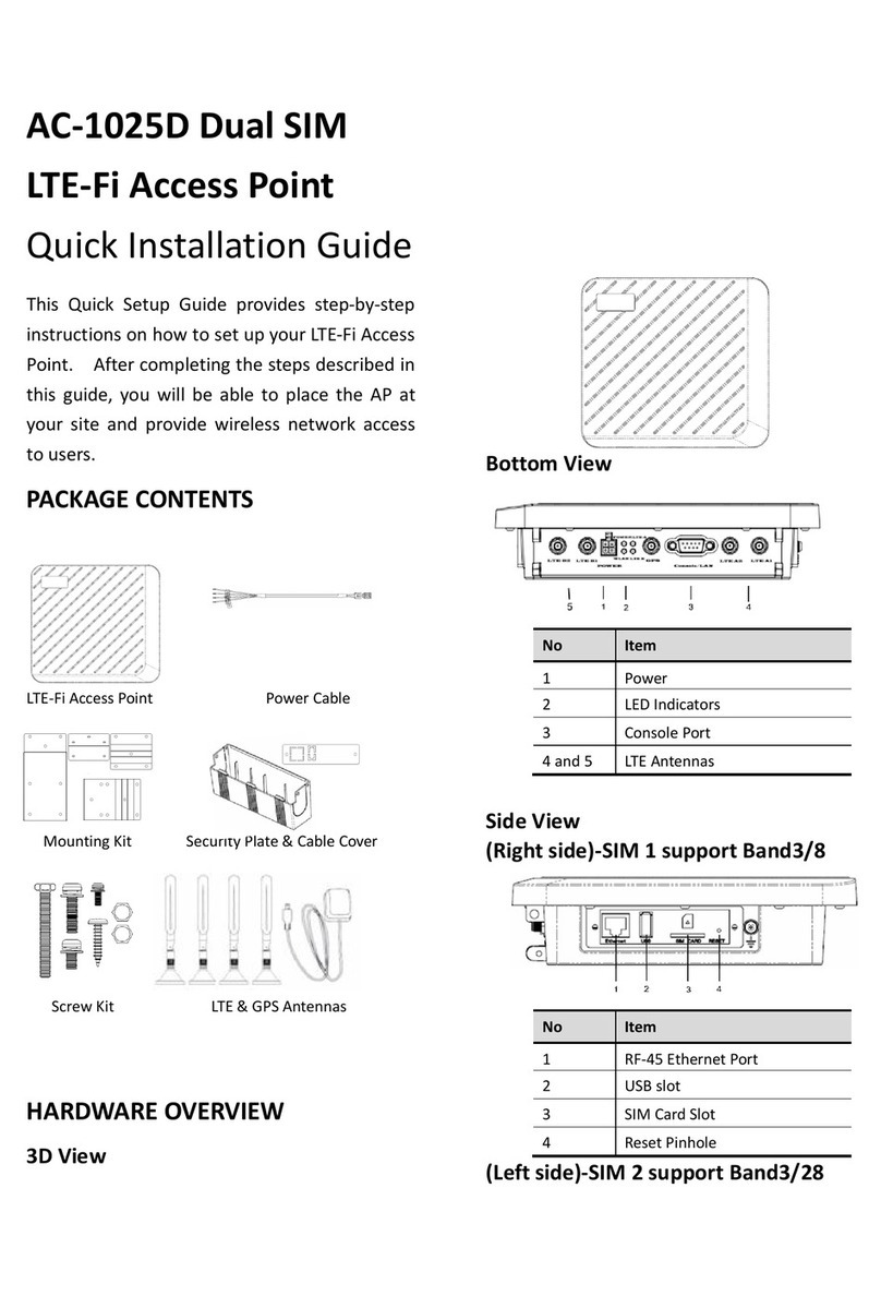
Zcom
Zcom AC-1025D User manual

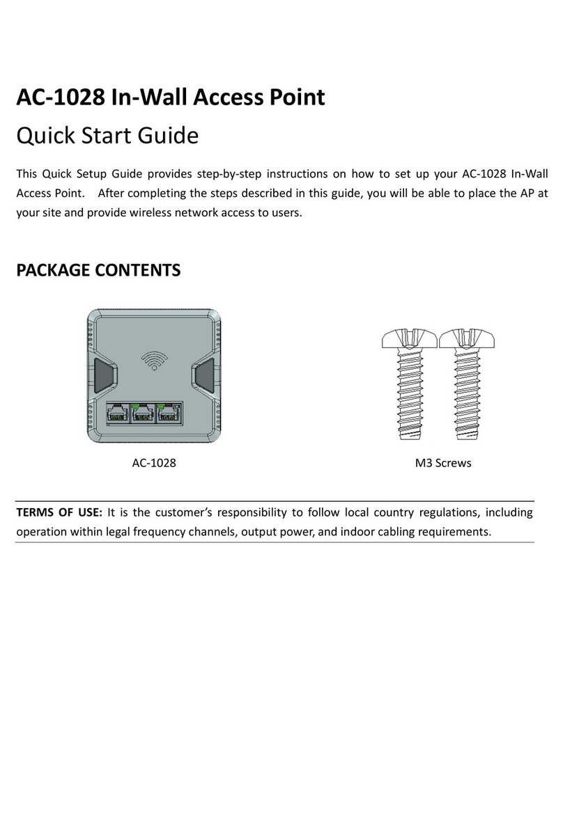
Zcom
Zcom AS220V2 User manual

Zcom
Zcom ZAC-1023-2 User manual

Zcom
Zcom XG-1020 User manual

Zcom
Zcom SP220V2 Series User manual

Zcom
Zcom ZAC Series User manual

Zcom
Zcom ZCN-1523H-2-8 User manual

Zcom
Zcom ZAC-1023-2-9 User manual

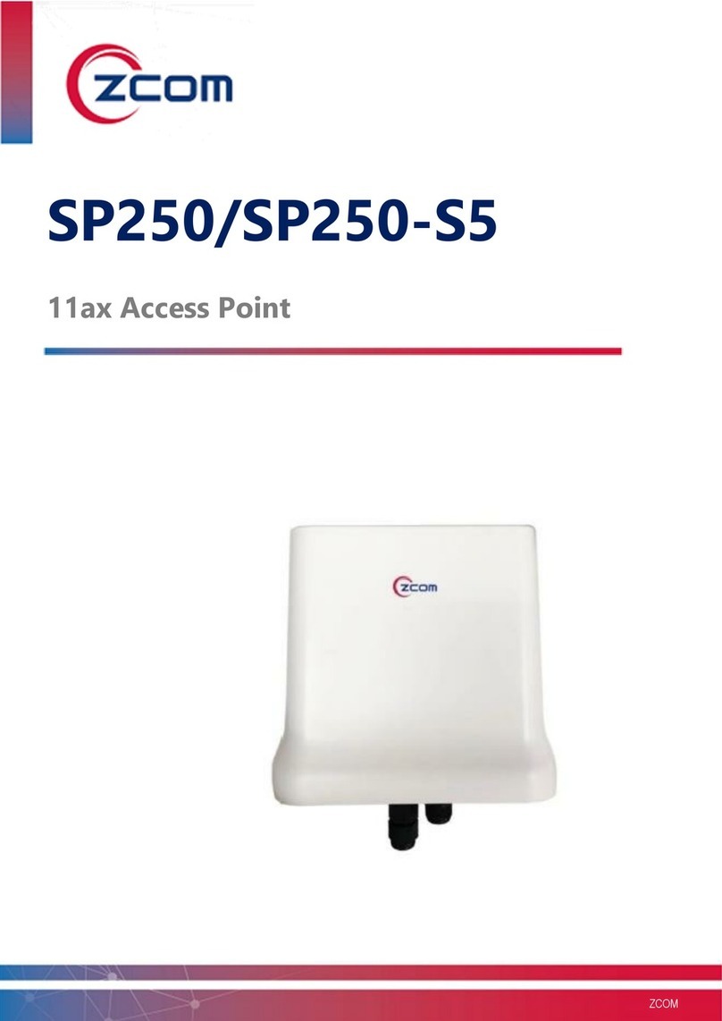
Zcom
Zcom SP230 Series User manual

Zcom
Zcom AS220V2 User manual

Zcom
Zcom ZAC-1023-5 User manual

Zcom
Zcom AS420 User manual

Zcom
Zcom XG-3120 User manual

Zcom
Zcom ZN-7100-DE500-G V4 User manual

Zcom
Zcom SP230 Series User manual

Zcom
Zcom XV-5850 User manual

Zcom
Zcom ZAC Series User manual

Zcom
Zcom AC-1028 User manual

Zcom
Zcom SP420 Series User manual