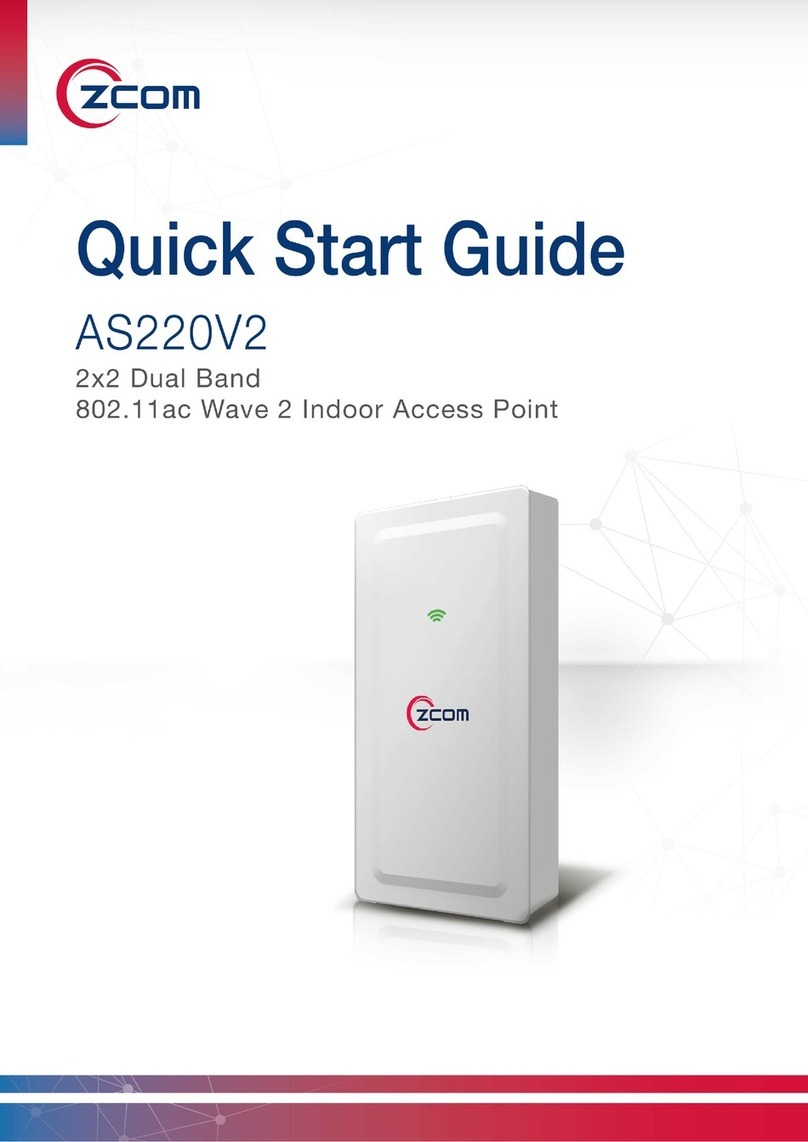
Zcom AS220V2 User manual

AS220V2 2x2 Dual Band 802.11ac Wave 2 Indoor Access Point QSG

AS220V2 2x2 Dual Band 802.11ac Wave 2 Indoor Access Point QSG
1
Package Contents
One indoor
access point
One mounting bracket
+ one screw
Two mounting bracket screws
+ screw anchors
One
allen wrench
One quick start guide
Note: If any of the items, mentioned above, are not included in the packaging or are
damaged in any way, contact your reseller immediately.
Installation Requirements
TERMS OF USE: All Ethernet cabling runs must use CAT5e, 24AWG (or above) Shielded Twisted Pair
(STP) cabling. It is the professional installer’s responsibility to follow local country regulations,
including operation within legal frequency channels, output power, indoor cabling requirements,
and Dynamic Frequency Selection (DFS) requirements.
Mounting the Access Point
In-wall mount
Determine where you want to mount the device, position the socket into the slot.
Insert the mounting bracket into the socket using
the two screws (included in the packaging).
Slide the device onto the mounting
bracket to finish the installation.
Note: Before lock two screws into the socket, please reserve space up to 15 cm in length
above bracket for installation.

AS220V2 2x2 Dual Band 802.11ac Wave 2 Indoor Access Point QSG
2
Wall mount
Determine where you want to mount the device, position the mounting bracket onto the wall,
and use a marker to mark the two screw holes on the wall.
Note: Before drill two holes into the wall, please reserve space up to 15 cm in length
above bracket for installation.
Drill the two holes into the wall and insert the two screw anchors (included in the packaging)
into the holes.
Install the mounting bracket onto the wall
using the two screws (included in the
packaging) into the screw plugs in the wall.
Slide the device onto the mounting bracket
to finish the installation.
Ceiling Mount (Optional accessory_AS-CLM4)
Determine where you want to mount the device, position the mounting bracket onto the ceiling
board.
Use a marker to locate the two screw holes on the ceiling, and drill the two holes into the ceiling.
Note: The thickness of ceiling board should be less than 15mm.
Insert the ceiling screw through the mounting
bracket, ceiling board, and ceiling mount as the
following picture.
Slide the device onto the mounting bracket
to finish the installation.

AS220V2 2x2 Dual Band 802.11ac Wave 2 Indoor Access Point QSG
3
Installing the Anti-tamper Lock (Optional accessory_AS-LK18)
Slide all the cables through their respective holes on the anti-tamper lock.
Install the mounting bracket; plug all the
cables into their respective ports on the
device before installing the anti-tamper lock.
Position the anti-tamper lock onto the
device and fasten the lock screw clock-wise
with special anti-tamper lock key.
Safety Notice
1. Do not install the device close to any electrical grounding device or lightning protection system.
Place the device’s own grounding and lightning protection system apart from any electrical
grounding device and lightning protection system as far as possible.
2. Protect components from electrostatic discharge: Please wear an ESD wrist strap or handle the
power adapter by its edge and do not touch any component or printed circuit boards,
especially for module device.
3. Make sure to keep the temperature and humidity of the installation location at an optimal
level.
4. An excellent grounding system guarantees the stable operation of device, as well as to protect
device from lightning, interference and electrostatic discharges.
5. If installed outdoors, the device may be damaged by lightning. We recommend that you install
additional lightning protection devices if necessary, considering the conditions in your area.
6. Supply stable power to the device. Unstable power may cause the device to malfunction. The
device supports PoE power supply and is recommended if the device is installed near grid lines
within less than 100 meters radius.

AS220V2 2x2 Dual Band 802.11ac Wave 2 Indoor Access Point QSG
4
Powering the Access Point
Connect to the WAN/PoE IN Port
Connect the PoE cable into the WAN/PoE IN
port of the device, then it will power on.
Connect to a power adapter
(Optional accessory_ AC-48052)
Connect the power adaptor into the DC port
of the device, then it will power on.
LED Indicator
Color
Behavior
Description
Red
Solid
Initializing
Blinking
Factory defaults, waiting to be integrated
Blue
Blinking
Device is busy updating its firmware; do not touch or unplug it
Green
Solid
Ethernet connection detected
Blinking
No Ethernet connection detected
Access Point Configuration
In a default access point configuration is TAP mode; the access point uses a DHCP client IP address.
Step 1. Make sure DHCP is enabled on the network. The access point must receive its IP address
through DHCP.
Note: Switching from DHCP to assign a static IP address or DNS and L2 discovery mode
to the access point, please refer to the user manual for more information.
https://www.zcom.com.tw/index/downloads
Step 2. Power on the access point. As the access point attempts to connect to the Wireless LAN
Controller (WLC), the status LED indicator blinks green. If the connection is successful, the
status LED indicator is steady green.
Step 3. If the access point cannot connect to the WLC by DHCP broadcast, please refer to the
Note: It's available to turn on the access point by either or .
Note: It is equipped with a secondary LAN/ PoE (Power Over Ethernet) out to power a
device such as an IP phone, a security camera, or another AS220V2. The input power
should be 802.3at (PoE+) standard, and the maximum output power of the PoE is 13
Watts.
Note: Do NOT attempt to connect any non-passive PoE devices to LAN port when PoE
pass-through is enabled. Otherwise the initial voltage may damage the powered device.

AS220V2 2x2 Dual Band 802.11ac Wave 2 Indoor Access Point QSG
5
following optional settings.
Optional: Set up the access point by your computer
Note: The following procedure assumes that Windows 10 is the operating system.
Procedures for other operating systems are similar.
Step 1. On your computer, configure your network adapter from the “Local Area Connection”
settings as follows:
˙StartControl PanelNetwork and Sharing CenterChange Adapter Settings
Step 2. Edit the TCP/IPv4 address setting as follows:
˙Local Area ConnectionPropertiesInternet Protocol Version 4(TCP/IPv4)
Properties
Note: Record all of the currently active settings so you can restore your computer to its
current configuration later (when this process is complete.)
Step 3. Select “Use the following IP address”and make the following entries:
˙IP address: 192.168.1.168 (or any available address in the 192.168.1.x network, except
192.168.1.1)
˙Subnet mask: 255.255.255.0
Leave the “Default gateway”and “DNS server”fields empty.
Step 4. Click “OK”to save your changes.
Login into the access point
Step 1. Launch a Web browser; type 192.168.1.1 URL to connect to the access point. When a
security alert dialog box appears, click OK/Yes to proceed.
Step 2. When login page appears, enter the following: Username: root/Password: password
Step 3. Click login.
Customizing the Wireless Settings
On the Web interface menu, Select StatusGeneral in the menu bar. Check your switchmod item
to select “Connect with via IP”, and setup your WLC IP address on “Wireless Switch Address 1”.
Note: In TAP mode, the access point must be able to go with WLCs for bulk configuration
and performing other commands of access points. Please refer to WLC QSG for more
information. https://www.zcom.com.tw/index/downloads
Note: If you need a standalone access point, please refer to the FAP mode configuration.

AS220V2 2x2 Dual Band 802.11ac Wave 2 Indoor Access Point QSG
6
FAP Mode
The default AP mode is TAP mode, before FAP configurations please change AP mode.
Step 1. If currently in TAP Mode: On the Web interface menu, click SystemAP mode.
Step 2. Select Fat AP from the drop-down list.
Step 3. Click save & apply to take effect.
Note: For FAP mode, please refer to the user manual for more information.
https://www.zcom.com.tw/index/downloads
Wi-Fi SON
Z-COM Wi-Fi SON accelerates the connection between devices, providing users a quick installation
and easy deployment capabilities. Please refer to the user manual for more information.
https://www.zcom.com.tw/index/downloads
Mobile APP
Z-COM offers the App for bridge mode settings, which is available from our website:
https://www.zcom.com.tw/index/downloads. Please research and download it to provision.
If necessary: reset button
If the access point needs to be reset, please press and
hold the reset button for more than ten seconds to
restore to factory default settings.
Technical Specifications
Physical
Dimensions
(L x W x H)
96 x 29.9 x 192 mm
(3.78 x 1.18 x 7.56 in)
WAN/PoE In Port
One 10/100/1000 Mbps port
Weight
500 grams (1.1 lbs.)
LAN/PoE Out Port
One 10/100/1000 Mbps port
Antenna
2.4GHz: Embedded 2dBi omni antennas
5GHz: Embedded 2.5dBi omni antennas
Power Supply
DC 48V, 0.5A PoE, or DC Jack (optional accessory)

AS220V2 2x2 Dual Band 802.11ac Wave 2 Indoor Access Point QSG
7
Physical
LAN/PoE Out
48V/13 Watts (Max.), Passive PoE (Pairs 4, 5+; 7, 8 Return)
Power Consumption
Max. 12 Watts
Environmental
Temperature
Humidity
Operating
-10°C to 60°C (14°F to 140°F)
10% to 90% (Non-condensing)
Storage
-20°C to 70°C (-4°F to 158°F)
10% to 90% (Non-condensing)
Compliance Information
RF Exposure Warning
The antennas used for this transmitter must be installed to provide a separation distance of at least
20 cm from all persons and must not be located or operating in conjunction with any other
antenna or transmitter.
CE Marking
CE marking on this product represents the product is in compliance with all directives that are
applicable to it.
Note: This device meets Max. TX power limit per ETSI regulations.
Note: This device is restricted to indoor use only when operating in the 5150 - 5350 MHz
frequency range within all member states.
RoHS/WEEE Compliance Statement
European Directive 2012/19/EU requires that the equipment bearing this symbol on the product
and/ or its packaging must not be disposed of with unsorted municipal waste. The symbol
indicates that this product should be disposed of separately from regular household waste streams.
It is your responsibility to dispose of this and other electric and electronic equipment via
designated collection facilities appointed by the government or local authorities. Correct disposal
and recycling will help prevent potential negative consequences to the environment and human

AS220V2 2x2 Dual Band 802.11ac Wave 2 Indoor Access Point QSG
8
health. For more detailed information about the disposal of your old equipment, please contact
your local authorities, waste disposal service, or the shop where you purchased the product.
Declaration of Conformity
Hereby, Z-COM, Inc. declares that the radio equipment type AS220V2 is in compliance with
Directive 2014/53/EU. The full text of the EU declaration of conformity is available at the following
internet address: https://www.zcom.com.tw/index/downloads
Optional Accessories
PN
Item
Picture
AS-CLM4
Ceiling mount + two screws
AS-LK18
Anti-tamper Lock
AC-48052
48 V 0.52A power adapter
Contact Information
All information may be changed by Z-COM at any time without prior notice or explanation to the
user. For further information please refer to our website: www.zcom.com.tw
Other manuals for AS220V2
2
Table of contents
Other Zcom Wireless Access Point manuals
Zcom
Zcom XG-580 PLUS User manual

Zcom
Zcom AS420 User manual

Zcom
Zcom ZAC-1023-2-9 User manual

Zcom
Zcom AC-1031 User manual

Zcom
Zcom ZCN-1523H-2-8 User manual

Zcom
Zcom ZAC Series User manual

Zcom
Zcom XG-3120 User manual

Zcom
Zcom XG-1020 User manual

Zcom
Zcom AS220V2 User manual
Zcom
Zcom SP230 Series User manual

Zcom
Zcom XV-5850 User manual

Zcom
Zcom AC-1028 User manual

Zcom
Zcom ZAC-1023-5 User manual

Zcom
Zcom ZN-7100-DE500-G V4 User manual

Zcom
Zcom SP420 Series User manual

Zcom
Zcom SP220V2 Series User manual

Zcom
Zcom AC-1025D User manual

Zcom
Zcom SP230 Series User manual

Zcom
Zcom ZAC-1023-2 User manual
Zcom
Zcom AS220V2 User manual