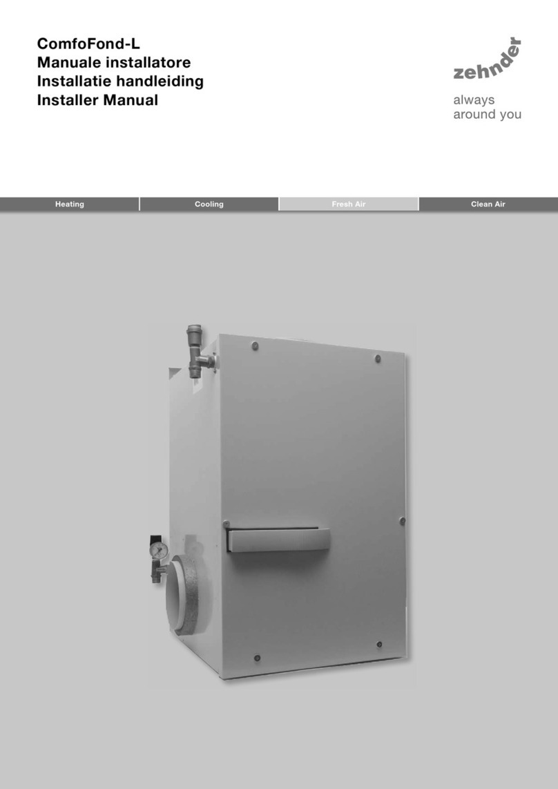
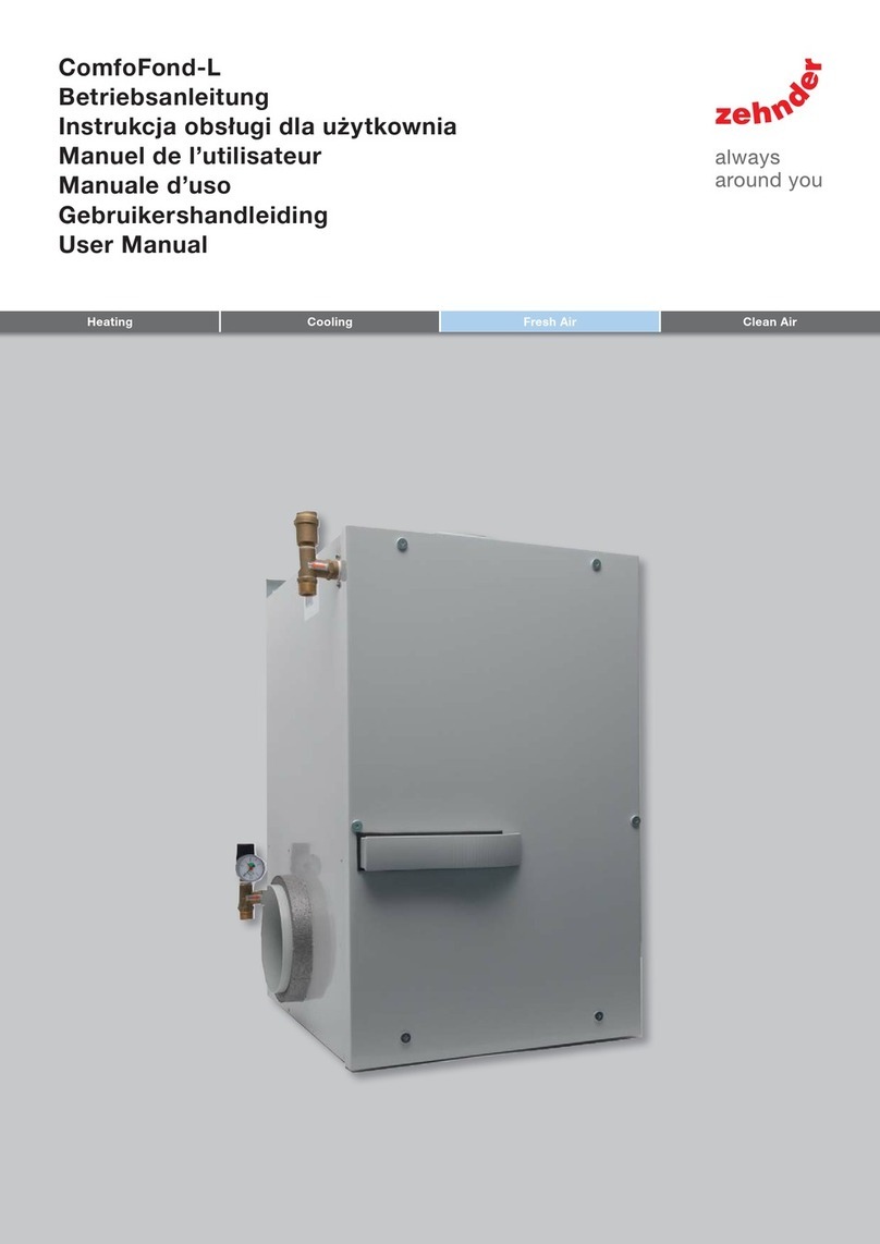
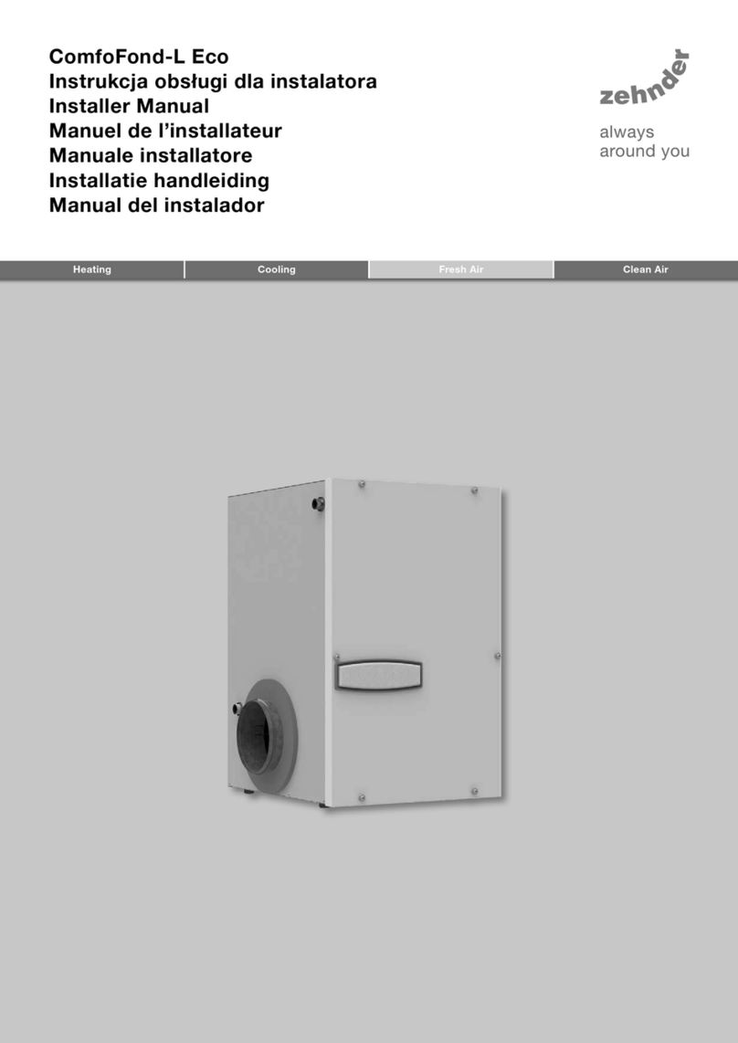
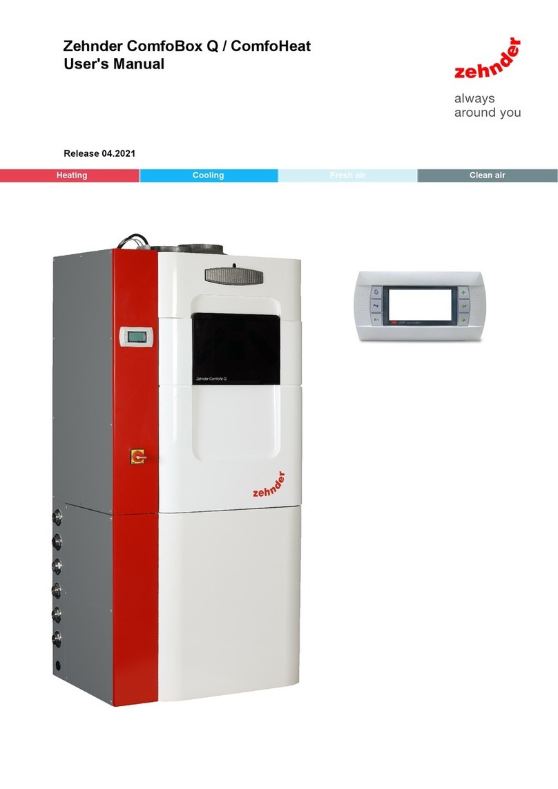
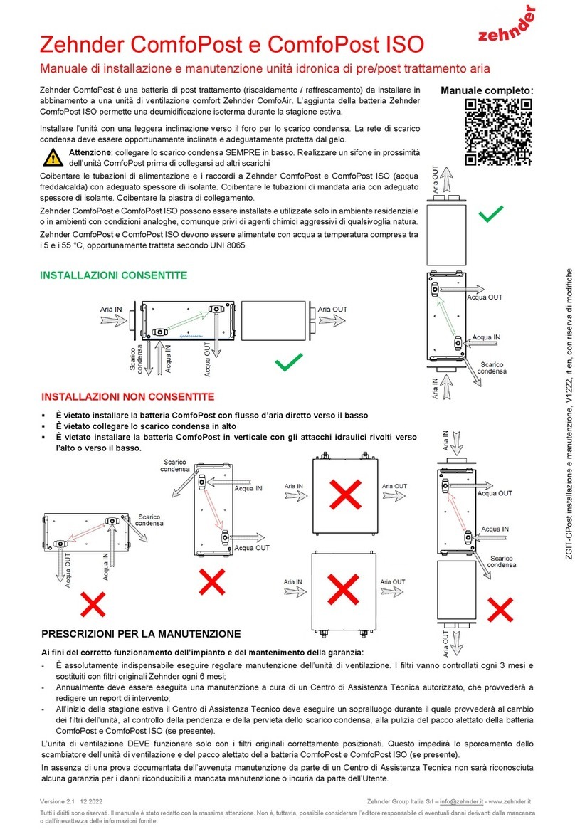
Zehnder Rittling ComfoFond-L User manual

Installation manual
Installatie handleiding
Installation Anleitung
Manuel de l’installateur
Manuale per l’installatore
Instrukcja obsługi
Comfofond-L
comfosystems

EN II
All rights reserved.
This documentation has been compiled with the utmost care. The publisher cannot be held liable for any damage caused as
a result of missing or incorrect information in this manual.

ENIII
Table of contents
FOREWORD.................................................................................................................................................... 1
1. INTRODUCTION.............................................................................................................................................. 2
2. TRANSPORT AND UNPACKING.................................................................................................................... 3
3. INSTALLATION CONDITIONS AND DIMENSIONAL SKETCHES ................................................................ 3
3.1 Dimensional sketch Comfofond-L 350 L .............................................................................................. 4
3.2 Dimensional sketch Comfofond-L 350 R.............................................................................................. 5
3.3 Dimensional sketch Comfofond-L 550 L .............................................................................................. 6
3.4 Dimensional sketch Comfofond-L 550 R.............................................................................................. 7
4. INSTALLATION ............................................................................................................................................... 8
4.1 Connecting the air ducting.................................................................................................................... 8
4.2 Wall mounting ....................................................................................................................................... 8
4.3 Connecting the condensation drain ..................................................................................................... 9
4.4 Connecting the brine loop (terrestrial heat collector).......................................................................... 10
4.5 Electrical connections......................................................................................................................... 11
5. COMMISSIONING ......................................................................................................................................... 12
5.1 Filling the brine loop............................................................................................................................ 12
5.2 Adjusting the uid pump..................................................................................................................... 13
5.3 Registering the Comfofond-L on the ComfoAir Luxe ......................................................................... 13
5.4 Adjusting the control temperatures..................................................................................................... 14
6. MAINTENANCE............................................................................................................................................. 15
6.1 For replacing lters ............................................................................................................................. 17
6.2 Cleaning condensation drain .............................................................................................................. 17
6.3 Inspecting brine loop .......................................................................................................................... 17
6.4 Cleaning internal siphon ..................................................................................................................... 17
6.5 Maintenance of Comfofond-L casing ................................................................................................. 17
6.6 Maintenance of Comfofond-L battery................................................................................................. 18
6.7 Replacing uid pump .......................................................................................................................... 18
6.8 Replacing expansion vessel................................................................................................................ 18
6.9 Replacing lling valve.......................................................................................................................... 18
6.0 Replacing pressure meter ................................................................................................................... 18
6.11 Replacing de-aerator .......................................................................................................................... 18
7. MALFUNCTIONS........................................................................................................................................... 19

EN IV
8. TECHNICAL SPECIFICATIONS.................................................................................................................... 20
8.1 Brine loop dimensions ........................................................................................................................ 20
8.2 Fluid mixture ....................................................................................................................................... 21
8.3 Fluid pump settings ............................................................................................................................ 21
8.4 Air resistance ...................................................................................................................................... 21
8.5 Cooling capacity ................................................................................................................................. 22
8.6 Heating capacity ................................................................................................................................. 22
8.7 Service parts ....................................................................................................................................... 23
9. CE CERTIFICATION AND WARRANTY ....................................................................................................... 24
I. INSTALLATION REPORT ............................................................................................................................. 25
II. MAINTENANCE LOG.................................................................................................................................... 26

EN1
FOREWORD
Read this manual carefully before use.
This manual contains all information required for safe
and optimal installation, operation and
maintenance of the Comfofond-L. The unit
is subjected to continual development and
improvement. There is therefore a possibility that the
Comfofond-L differs slightly from the descriptions
given.
Applicable pictograms
The following pictograms are used in this manual:
Point to watch.
Risk of:
- damage to the device;
- performance of the unit is
compromised if instructions are
not observed carefully.
Risk of personal injury for the
user or fitter.
Questions
Please contact the supplier if you have any
questions. On the rear ap of this manual is a list with
the contact details of the main suppliers.
NOTE
This manual has been compiled with the
greatest care.
However, no rights can be derived from
it. In addition, we at all times reserve
the rights to change the contents of this
manual without prior notification.

EN 2
1. Introduction and safety
What is this unit for?
The Comfofond-L is a uid geothermal exchanger,
also known as a terrestrial heat exchanger. The
Comfofond-L heats or cools the outdoor air using
terrestrial heat. The heated or cooled outdoor air is
then led into the dwelling.
Function
1. Brine loop
2. Comfofond-L
3. ComfoAir Luxe
Brine loop pipes are laid in the ground and
connected to the dwelling. In the winter the cold
outdoor air is preheated, ensuring the ventilation
system continues to operate effectively even at low
temperatures. In the summer the warm outdoor air is
precooled.
The Comfofond-L is specially developed to operate
in combination with a Zehnder ventilation system
of type ComfoAir 350 Luxe or ComfoAir 550 Luxe.
The required pump control for the Comfofond-L is
integrated in this ventilation system as standard.
The ventilation unit installation manual covers
in greater detail ventilation issues and how the
ventilation system works. A copy of this manual can
be obtained from Zehnder.
Safety instructions
Always comply with safety regulations in this manual.
Personal injury or damage to the Comfofond-L
can arise from non-compliance with the safety
regulations, warnings, comments and instructions in
this manual.
• The Comfofond-L may only be tted, connected,
commissioned and set up by a registered
installer.
• Installation of the Comfofond-L must be carried
out in accordance with the general and locally
applicable construction, safety and installation
instructions of the local council, electricity and
water boards.
• Always follow the safety regulations, warnings,
comments and instructions given in this manual.
• Store the manual in the vicinity of the
Comfofond-L for its entire working life.
• Modications to the Comfofond-L or its manual
are not permitted.
• Only a recognized cooling-technology tter may
top up the Comfofond-L or perform maintenance
on parts of the brine loop.
• The uid in the brine loop is pressurised. The
system must be de-pressurised in a controlled
manner if maintenance is required on the brine
loop. Use the taps and lling valves in the unit to
do this.
• When carrying out any work on the Comfofond-L,
make sure the power is disconnected and cannot
be inadvertently reconnected.
To disconnect the Comfofond-L, you must
disconnect the ComfoAir Luxe from the power
supply to which it is connected.
1
2
3

EN3
2. Transport and unpacking
Take care when transporting and unpacking the
Comfofond-L.
Make sure the packing material is disposed
of in an environmentally friendly manner.
Checking delivery
Contact your supplier immediately in case of damage
or an incomplete
delivery.
The delivery must include:
Comfofond-L 350:
• Comfofond-L; Check the identication plate to
ensure that it is the required type;
• Filter with separate lter handle;
• Condensation drain connection;
• Wall bracket;
• Insulation belt;
• Manual.
Comfofond-L 550:
• Comfofond-L; Check the identication plate to
ensure that it is the required type;
• Filter with separate lter handle;
• Condensation drain connection;
• Wall bracket;
• 2 x 90º connection bends.
The connection bends are on the inside of
the Comfofond-L. Therefore the front of the
Comfofond-L must be removed to check the
delivery.
• Plastic sleeve joint;
• Metal sleeve joint;
• Manual.
The Comfofond-L is supplied in the following types:
Type:
Comfofond-L 350 L Comfofond-L 350 R
Comfofond-L 550 L Comfofond-L 550 R
Meaning of the sufces:
• Comfofond-L = Fluid geothermal exchanger.
• 350 = Suitable for a ComfoAir 350 Luxe.
• 550 = Suitable for a ComfoAir 550 Luxe.
• L = Concerns a left-side model for a left-side
ComfoAir.
• R = Concerns a right-side model for a right-side
ComfoAir.
3. Installation conditions and
dimensional sketches
In order to determine whether the Comfofond-L can
be installed in a certain area, the following aspects
must be taken into account:
• The Comfofond-L must be installed according
to the general and locally applicable safety
and installation regulations of power and water
companies, as well as the instructions in this
manual;
• The system must be tted to allow sufcient
room around the Comfofond-L and ComfoAir
Luxe for the air connections and brine loops as
well as for carrying out maintenance activities;
• The room must offer the following provisions:
- Air duct connections.
- 230V electrical connection.
- Provisions for the condensation drain.
- Brine loops for the pipe system.
• The Comfofond-L must be installed in a frost-free
space;
The fluid in the system may not freeze.
Irreversible damage will be caused to the
machine if the fluid freezes.
• The condensation must be drained off frost-free,
at a gradient, using a siphon;
• We recommend that the Comfofond-L is not
installed in spaces with a higher average
humidity (such as a bathroom or toilet). This is
to prevent the formation of condensation on the
outside of the Comfofond-L.
• An outer valve is a requirement if the system is
used in areas where the temperature is lower
than -15ºC. This valve must shut off the supply
air in the event of a power failure. The system
can be damaged during a power failure at
temperatures lower than -15ºC, this is why an
outer valve is a requirement.
EN 4
3.1 Dimensional sketch Comfofond-L 350 L
Elevation P

EN5
3.2 Dimensional sketch Comfofond-L 350 R
Elevation P

EN 6
3.3 Dimensional sketch Comfofond-L 550 L
Elevation P

EN7
3.4 Dimensional sketch Comfofond-L 550 R
Elevation P

EN 8
4. Installation
4.1 Connecting the air ducting
Take account of the following factors when mounting
air ducting:
• Only use the supplied connecting material
between the Comfofond-L and ComfoAir Luxe;
• Insulate the outdoor air supply duct between
the roof-/facade duct and the Comfofond-L
vapour-proof. This prevents the formation of
condensation on the outside of the ducts;
• The air outlet on the Comfofond-L must be
connected to the outdoor air connection on the
ComfoAir Luxe;
• The air outlet on the Comfofond-L 350 is on
the side of the Comfofond-L at the top.
• The air outlet on the Comfofond-L 550 is on
the upper side of the Comfofond-L.
• The outdoor air must be connected to the air
inlet on the Comfofond-L. The air inlet on the
Comfofond-L is on the side of the Comfofond-L
at the bottom.
outdoor air
supply air supply air
Comfofond-L 350 Comfofond-L 350
Left Right
outdoor air
supply air supply air
Comfofond-L 550 Comfofond-L 550
Left Right
4.2 Wall mounting
Mount the Comfofond-L against a wall with a
minimum mass of 200 kg/m2. The Zehnder base
frame (optional extra) must be used for other walls.
This reduces contact noise as much as possible.
Comfofond-L 350 Comfofond-L 550
Make sure to leave a minimum space of 110 cm in
front of the Comfofond-L in view of the necessary
maintenance work.
Where necessary, reposition the ComfoAir
Luxe documentation to make sure it is still
accessible following the installation of the
Comfofond-L.
Comfofond-L 350:
1. Mount the suspension bracket supplied with
the unit to the wall, ensuring it is level. Both
suspension brackets must be tted at the same
height.
2. Place the Comfofond-L in the suspension
bracket.
3. Fit the supplied insulation belt (A) between the
niche pipe and the connecting bend (outdoor
air) of the ComfoAir 350 Luxe. This prevents
condensation formation.
A
A. insulating belt
4. Tape off (not included) all air connections on the
Comfofond-L and the ComfoAir Luxe vapour-
proof.
5. Fit the condensation drain to the underneath of
the Comfofond-L.

EN9
Comfofond-L 550:
1 Mount the suspension bracket supplied with
the unit to the wall, ensuring it is level. Both
suspension brackets must be tted at the same
height.
2. Place the Comfofond-L in the suspension
bracket.
3. Place the metal sleeve joint (A) on the niche pipe
(outdoor air) of the ComfoAir 550 Luxe.
4. Use the plastic sleeve joint to connect both 90º
connection bends (B).
5. Place the connected 90º connection bends on
the metal sleeve joint (A) of the ComfoAir and the
air exhaust of the Comfofond-L.
6. Tape off (not included) the plastic sleeve joint (B)
and all air connections on the Comfofond-L and
the ComfoAir Luxe vapour-proof.
A
A. Metal sleeve joint
B. Plastic sleeve joint
7. Fit the condensation drain to the underneath of
the Comfofond-L.
4.3 Connecting the condensation drain
Take account of the following factors when tting the
condensation drain:
• The condensation must be drained off frost-free,
at a gradient, using an appropriate siphon;
• Connect the condensation drain (air-tight) via a
pipe or a hose with a siphon (with a water seal of
at least 60mm) to the sanitary pipework;
• Position the upper edge of the siphon at least 40
mm underneath the condensation drain of the
Comfofond-L.
Comfofond-L 350
Comfofond-L 550
The condensation drains of the
Comfofond-L and the ComfoAir Luxe must
always be connected with a siphon.

EN 10
4.4 Connecting the brine loop (terrestrial
heat collector)
Insulate all brine loops (C) on the
brine loop. This prevents the formation of
condensation on the outside of the brine loop.
The Comfofond-L uses a terrestrial heat collector
which extracts heat from the ground and transfers
this to the air that ows through the Comfofond-L.
The terrestrial heat collector is formed by a PE pipe.
The length of the pipe is subject to local conditions,
such as the type of ground and the ground water
level. Solid ground contains more energy that loose
ground. If the pipe is below ground water level, then
substantial quantities of energy can be extracted at
the base.
The pipe must be horizontally positioned in the
ground (more or less) at an ideal depth of 1.5 to 2.5
metres, but certainly no deeper than 8 meters.
When calculating the length of the pipe, the actual
length for the calculation is the length that is
physically in the ground. The length inside the house
has no further effect on the energy that the system
can extract. The required pipe length for sandy soil is
twice as long.
The correct length of pipe can be
determined using the Comfofond-L
specifications. Zehnder has special software
available for calculating the required pipe
length.
The pipe can be laid in any random form. The
preferred situation is to lay the pipe in the ground
around the house and keep the length inside the
house to a minimum. In order to increase the
efciency, a minimum distance of 50 cm between
any loops in the pipe is advised.
Use an adaptor to connect one end of the PE pipe to
the uid connection inlet (A) of the Comfofond-L.
Use an adaptor to connect the other end of the
PE pipe to the uid connection outlet (B) of the
Comfofond-L.
Both connections are ¾” conical male-threaded.
B
A
C
An installation report has been included at
the rear of this manual which can be used to
note the details of the brine loop laid.

EN11
M
M
RS232
Zwart
Rood
Bruin
M
Wit
Bruin
Blauw (-)
Geel (0-10V)
Wit
M
badkamerschakelaar
Vorstvrij element
T1
T4
T3
T2
Bypassklep Vorstvrij elementklep
Groen/Geel
Brown
Blue
Blue
Brown
(L1) Grijs
(L2) Zwart
(L3) Bruin
(N) Blauw
Afvoer
Toevoer
RJ45
Display
VENT.
VENT.
FILT2/T4T1/T3BYP/PIE TRI
VENT. BS
VENT.
1
T2/T4T1/T3BYP/PIE
-
+
Wit
Groen/Geel
Groen/Geel
Rood
Zwart
Wit
Bruin
Wit
Bruin
Wit ( )
Geel (0-10V)
Blauw (-)
RS232 - PC
GND
12V
Eb
Ea
GND
12V
12V
Ab
CCb
Aa
CCa
GND
GND
Ext. Comm.
NL3 PE
Comm. Basis
RS232 - KFB
12V
RX
TX
ERR
GND
OFF
BS
GND
GND
FIE
CH
GND
GND
Tch
Tge
GND
GND
Tah
010
GND
GND
010
AH
ERR
T Geothermal
exchanger
(Tge)
E / C L2
NN
L1 PE PE
PE PE
GND
wasem
LNPE
Spare
Spare
Spare
Spare
Spare
12V
hb
ha
GND
010
GND
010
12V
Luxe connection printed circuit board
of the ComfoAir Luxe
Fluid pump
4.5 Electrical connections
The Comfofond-L is controlled and fed by the
ComfoAir Luxe. To do so, the temperature sensor
and uid pump of the Comfofond-L must be
connected to the Luxe connection printed circuit
board on the ComfoAir Luxe. This Luxe connection
printed circuit board is on the top of the ComfoAir
Luxe.
The temperature sensor must be connected to the
clamps that are marked with the text Tge and GND.
This sensor is not sensitive to direction. Therefore, it
does not matter which wire is connected to the Tge
or GND clamp.
The uid pump must be connected to the supply
block on the Luxe connection printed circuit
board. As the Comfofond-L pump is not constantly
operational, this is connected to a power supply that
is switched by the ComfoAir Luxe. This power supply
is on the clamp marked with the text C. (The E clamp
next to this is a constant power supply that is used
for lling the Comfofond-L).

EN 12
5. Commissioning
All loose parts, including cardboard and
packaging materials must be removed from
the system before commissioning.
5.1 Filling the brine loop
During standard operation of the Comfofond-L, taps
V2 and V4 are open and the lling valves V1 and V3
are closed. The Comfofond-L is lled via the lling
valves V1 and V3.
The tap is open when the handle is parallel to the
pipe. The tap is closed when the handle is at a right
angle to the pipe.
5
4
3
1
2
15
7
6
8
9
10
V1
V3
V2
V4
16
12
14
13
11
17
V1. ¾” lling valve
V2. tap
V3. ¾” lling valve
V4. tap
1. 180 mm Ø air inlet
2. ¾” inlet uid connection
3. pressure meter
4. ¾” outlet uid connection
5. de-aerator
6. air lter
7. air outlet
Comfofond-L 350: 160 mm Ø side
Comfofond-L 550: 180 mm Ø upper side
8. uid pump
9. expansion vessel
10. detachable air partition
11. temperature sensor
12. lower drip tray
13. upper drip tray
14. battery
15. condensation drain 1 ¼” with 32 mm adapter
16. temperature sensor and coolant pump
connection
17. internal siphon
All brine loop connections are conical
male-threaded.
Filling instructions
Only a recognized cooling-technology fitter
may top up the Comfofond-L.
Proceed as follows:
1. Disconnect the ComfoAir Luxe from its power
supply.
2. Remove the cover on top of the ComfoAir Luxe.
3. Reposition the phase wire from the Comfofond-L
to the adjacent E clamp.
4. Remove the lter handle from the Comfofond-L.
5. Release the front panel by removing the 6
screws.
6. Remove the front panel from the Comfofond-L.
7. Set the uid pump to the highest setting by
turning the switch on the pump to setting 7.
8. Connect a lling hose with external lling pump
to lling valve V3.
9. Connect a drainage hose to lling valve V1.
10. Place the open end of the drainage hose in a
bucket.
11. Open lling valves V1 and V3.
12. Close tap V2.
13. Open the de-aerator cap.
14. Supply power to the ComfoAir Luxe.
- The Comfofond-L pump will now run
constantly.
15. Fill the system with the uid using the external
lling pump until the uid runs out of the
drainage hose.
Do not run the Comfofond-L pump without
fluid for longer than 2 minutes.
Only fill the system with a ready-made
fluid mixture. The correct fluid mixture
can be determined using the Comfofond-L
specifications.
16. Close lling valve V1.
17. Open tap V2.
18. Pre-pressurise the system to 1.5 bar using the
water pressure from the mains. Use the lling
hose on lling valve V3 for this.
19. Pump the mixture through the system for
approximately 30 minutes to ensure that any air
pockets can exit the system via the de-aerator.
20. Check the system pressure again and add more
in order to increase pressure if necessary.
21. Close lling valve V3 and disconnect the lling
hose.
22. Disconnect the ComfoAir Luxe from its power
supply.
23. Return the phase wire from the Comfofond-L
back to the original position on C clamp.
24. Adjust the uid pump to the correct setting.
More information about this is available in the
'Adjusting the uid pump' section.
25. Install all parts in reverse order. (from point 6
back to point 1)

EN13
An installation report has been included at
the rear of this manual which can be used
to note the details of the fluid used.
5.2 Adjusting the uid pump
The fluid pump supports two user modes.
The "constant pressure" mode is always
used on the Comfofond-L.
Variable pressure. Constant pressure.
The Comfofond-L uses a
uid pump to pump the uid through the brine loop.
This uid pump must be adjusted correctly to achieve
the best possible performance of the Comfofond-L
. The uid pump setting is subject to the ComfoAir
Luxe type:
- The uid pump for the Comfofond-L 350 must
achieve a ow rate of 6-8 litres per minute.
- The uid pump for the Comfofond-L 550 must
achieve a ow rate of 8-10 litres per minute.
The pump setting is subject to:
• the total length of the terrestrial heat collector;
• the internal diameter of the terrestrial heat
collector;
• the composition of the uid mixture;
• the temperature of the uid mixture;
The correct setting for the fluid pump can
be determined using the Comfofond-L
specifications.
An installation report has been included at
the rear of this manual which can be used
to note the setting used.
5.3 Registering the Comfofond-L on the
ComfoAir Luxe
The control for the Comfofond-L is not activated
as standard on the ComfoAir Luxe. This must be
registered rst.
This is done by selecting option "1" in P-menu
"P60".
Registering via display
1. Press “
OK
MENU
·
·
·
”.
- “P2” will be displayed on the screen.
2. For 3 seconds, press simultaneously on “
OK
MENU
·
·
·
”
and “
OK
MENU
·
·
·
”.
- “P3” will be displayed on the screen.
3. Press “
OK
MENU
·
·
·
” 3 times.
- “P6” will be displayed on the screen.
4. Press “ OK
MENU
·
·
·
”.
- “P60” will be displayed on the screen.
5. Press “ OK
MENU
·
·
·
”.
- Current setting of P-menu P60 will be
displayed on the screen.
6. Press“
OK
MENU
·
·
·
” until “1” is displayed on the
screen.
7. Press “ OK
MENU
·
·
·
”.
- “P60” will be displayed on the screen.
8. Press “
OK
MENU
·
·
·
” 2 times.
- Current ventilation setting will be displayed
on the screen.
Registering via CC-Ease
1. Press“ ” and “ ” together for 3 seconds.
- “P2” will be displayed on the screen.
2. Press“ ” and “ ” together for 3 seconds.
- “P3” will be displayed on the screen.
3. Press “ ” 3 times.
- “P6” will be displayed on the screen.
4. Press “ ”.
- “P60” will be displayed on the screen.
5. Press “ ”.
- Current setting of P-menu P60 will be
displayed on the screen.
6. Press“ ” until “1” is displayed on the screen.
7. Press “ ”.
- “P60” will be displayed on the screen.
8. Press “ ” 2 times.
- The main screen will be displayed on the
screen.

EN 14
Registering via CC-Luxe
1. Press “ Settings ”.
- A new menu will be displayed on the screen.
2. Press “ System ”.
- A new menu will be displayed on the screen.
3. Press “
OK
MENU
·
·
·
”.
- The second section of the menu will be
displayed on the screen.
4. Press “ Service login ”.
- A code entry screen will be displayed on the
screen.
5. Enter the code “3520”.
- A new menu will be displayed on the screen.
“Artic” is selected/white.
6. Press “
OK
MENU
·
·
·
”
- Ventilation will be selected/white.
7. Press “ OK
MENU
·
·
·
”.
- A new menu will be displayed on the screen.
“P3 Ventilation” is selected/white.
8. Press “
OK
MENU
·
·
·
” 3 times.
- “P6 options” will be selected/white.
9. Press “ OK
MENU
·
·
·
”.
- A new menu will be displayed on the screen.
“P60 Base exchanger” is selected/white.
10. Press “ OK
MENU
·
·
·
”.
- Current setting of P-menu P60 will be
displayed on the screen.
11. Press“
OK
MENU
·
·
·
” until “1” is displayed on the
screen.
12. Press “ OK
MENU
·
·
·
”.
- A new menu will be displayed on the screen.
“P60 Base exchanger” is selected/white.
13. Press “
OK
MENU
·
·
·
” 2 times.
- The main screen will be displayed on the
screen.
5.4 Adjusting the control temperatures
The ComfoAir Luxe switches the uid pump of the
Comfofond-L on and off at pre-set temperatures.
These desired temperatures can be set in the
P-menus "P62" and "P63" of the ComfoAir Luxe.
• In the Winter mode, the ComfoAir Luxe will
switch around the temperature that is set in
P-menu "P62".
The best setting for P-menu P62 is a few
degrees below the lowest uid temperature. The
lowest uid temperature is a few degrees below
the average local annual temperature.
• In the Summer mode, the ComfoAir Luxe will
switch around the temperature that is set in
P-menu “P63”.
The best setting for P-menu P63 is a few
degrees above the set comfort temperature of
the ComfoAir Luxe.
The minimum and maximum values for the
available settings parameters are preset in
the software of the ComfoAir Luxe.
The uid pump of the Comfofond-L will be activated
if:
• The temperature sensor of the Comfofond-L
measures a temperature lower than the
temperature that is set in menu P62 when in
Winter mode;
• The temperature sensor of the Comfofond-L
measures a temperature higher than the
temperature that is set in menu P63 when in
Summer mode.
The uid pump of the Comfofond-L will be
deactivated if:
• The temperature sensor of the Comfofond-L
measures a temperature higher than the
temperature that is set in menu P62 when in
Winter mode;
• The temperature sensor of the Comfofond-L
measures a temperature lower than the
temperature that is set in menu P63 when in
Summer mode.
An installation report has been included at
the rear of this manual which can be used to
note the set temperatures.

EN15
Adjusting temperature via display
1. Press “
OK
MENU
·
·
·
”.
- “P2” will be displayed on the screen.
2. For 3 seconds, press simultaneously on “
OK
MENU
·
·
·
”
and “
OK
MENU
·
·
·
”.
- “P3” will be displayed on the screen.
3. Press “
OK
MENU
·
·
·
” 3 times.
- “P6” will be displayed on the screen.
4. Press “ OK
MENU
·
·
·
”.
- “P60” will be displayed on the screen.
5. Use “
OK
MENU
·
·
·
” to select the desired P-menu (P62
or P63).
6. Press “ OK
MENU
·
·
·
”.
- Current setting of selected P-menu will be
displayed on the screen.
7. Use “
OK
MENU
·
·
·
” or “
OK
MENU
·
·
·
” to select the desired
temperature.
8. Press “ OK
MENU
·
·
·
”.
- “P60” will be displayed on the screen.
9. Press “
OK
MENU
·
·
·
” 2 times.
- Current ventilation setting will be displayed
on the screen.
Setting temperature via CC-Ease
1. Press “ ” and “ ” together for 3 seconds.
- “P2” will be displayed on the screen.
2. Press“ ” and “ ” together for 3 seconds.
- “P3” will be displayed on the screen.
3. Press “ ” 3 times.
- “P6” will be displayed on the screen.
4. Press “ ”.
- “P60” will be displayed on the screen.
5. Use “ ” to select the desired P-menu (P62 or
P63).
6. Press “ ”.
- Current setting of selected P-menu will be
displayed on the screen.
7. Use “ ” or “ ” to select the desired
temperature.
8. Press “ ”.
- “P60” will be displayed on the screen.
9. Press “ ” 2 times.
- The main screen will be displayed on the
screen.

EN 16
Setting temperature via CC-Luxe
1. Press “ Settings ”.
- A new menu will be displayed on the screen.
2. Press “ System .
- A new menu will be displayed on the screen.
3. Press “
OK
MENU
·
·
·
”.
- The second section of the menu will be
displayed on the screen.
4. Press “ Service login ”.
- A code entry screen will be displayed on the
screen.
5. Enter the code “3520”.
- A new menu will be displayed on the screen.
“Artic” is selected/white.
6. Press “
OK
MENU
·
·
·
”.
- Ventilation will be selected/white.
7. Press “ OK
MENU
·
·
·
”.
- A new menu will be displayed on the screen.
“P3 Ventilation” is selected/white.
8. Press “
OK
MENU
·
·
·
” 3 times.
- “P6 options” will be selected/white.
9. Press “ OK
MENU
·
·
·
”.
- A new menu will be displayed on the screen.
“P60 Base exchanger” is selected/white.
10. Use “
OK
MENU
·
·
·
” to select the desired P-menu (P62
or P63).
11. Press “ OK
MENU
·
·
·
”.
- Current setting of selected P-menu will be
displayed on the screen.
12. Use “
OK
MENU
·
·
·
” or “
OK
MENU
·
·
·
” to select the desired
temperature.
13. Press “ OK
MENU
·
·
·
”.
- A new menu will be displayed on the screen.
“P60 Base exchanger” is selected/white.
14. Press “
OK
MENU
·
·
·
” 2 times.
- The main screen will be displayed on the
screen.
6. Maintenance
Failure to carry out (periodic) maintenance
on the Comfofond-L ultimately compromises
the performance of the system.
To ensure a hassle-free lifespan for your
Comfofond-L, we recommend you take out a service
agreement with an expert company.
The following maintenance may be carried out
by the user:
• Replacing the lter;
• Cleaning the condensation drain;
• Checking the system pressure.
The following maintenance may be carried out
by the tter:
• Inspecting the brine loop;
• Cleaning the internal siphon;
• Inspecting and cleaning the Comfofond-L
casing;
• Inspecting and cleaning the Comfofond-L
battery;
• Replacing the uid pump (where required);
• Replacing the expansion vessel (where required);
• Replacing the lling valve (where required);
• Replacing the pressure meter (where required);
• Replacing the de-aerator (where required);
A concise explanation of these maintenance
activities is given in the paragraphs below.
Ensure the Comfofond-L has been
disconnected from mains power before
carrying out any maintenance work. To do
this disconnect the ComfoAir Luxe from the
power supply to which it is connected.
Bear in mind that the
brine loop is pressurised.
Only a recognized cooling-technology fitter
may top up the Comfofond-L or perform
maintenance on parts of the brine loop.
A maintenance log has been included at the
rear of this manual which can be used to
note all performed maintenance.
For maintenance of the ComfoAir Luxe, please read
the instructions in the ComfoAir Luxe manual. A
copy of this manual can be obtained from Zehnder.
Other manuals for ComfoFond-L
1
This manual suits for next models
4
Table of contents
Other Zehnder Rittling Industrial Equipment manuals

Zehnder Rittling
Zehnder Rittling ComfoFond-L User manual

Zehnder Rittling
Zehnder Rittling ComfoFond-L Q Series User guide

Zehnder Rittling
Zehnder Rittling ZFC 3010 User manual

Zehnder Rittling
Zehnder Rittling ComfoPost Manual

Zehnder Rittling
Zehnder Rittling ComfoClime 24 User guide

Zehnder Rittling
Zehnder Rittling ComfoVar Aero Supply Zone 125 Manual

Zehnder Rittling
Zehnder Rittling ComfoFond-L Series User guide

Zehnder Rittling
Zehnder Rittling ComfoBox Q User manual

Zehnder Rittling
Zehnder Rittling ComfoFond-L Q User manual

Zehnder Rittling
Zehnder Rittling ComfoAir XL User guide