Zippie Kid Kart Xpress User manual

Owner’s Manual
Kid Kart® Xpress by Zippie®
*with transit option *without transit option
Supplier: This manual must be given to the user of
this wheelchair.
User: Before using this wheelchair read this entire
manual and save for future reference.
Kid Kart Xpress
M a n u e l
d ’ i n s t r u c t i o n s
*avec option pour transport *sans option pour
transport
Au Fournisseur : Ce manuel doit être remis à l’usager de
ce fauteuil roulant.
À l’Usager : Veuillez lire tout le manuel et le conserver pour
rérérence ultérieure.
Chaque fauteuil est livré avec un manuel d’instructions en anglais. La version en français est
à votre disposition en format PDF sur le site : www.SunriseMedical.com. Veuillez vous
rendre à la page de votre produit pour télécharger le manuel dans la langue souhaitée, ou
contactez un fournisseur agréé Sunrise Medical.
M a n u a l
d e n s t r u c c i o n e s
Kid Kart® Xpress by Zippie®
*con opción de tránsito * sin opción de tránsito
Distribuidor: Este manual debe ser entregado al pasajero de esta
silla de ruedas.
Pasajero: Antes de usar esta silla de ruedas, lea este manual en
su totalidad y guárdelo para futura referencia.
Cada una de las sillas se envía con un manual de instrucciones en inglés. El manual en
español está disponible en formato PDF en nuestra página en nternet:
www.SunriseMedical.com. ngrese a la página del producto específico para descargar el
manual, o comuníquese con el proveedor autorizado de Sunrise Medical.
Kid Kart® Xpress by Zippie®

DISPOSAL AND RECYCLING INFORMATION
When this product reaches the end of its life, please take it to an approved
collec-tion or recycling point designated by your local or state government.
This wheelchair is manufactured using a variety of materials, Your product
should not be disposed of as ordinary household waste. You should dispose of
your wheelchair properly, according to local laws and regulations. Most
materials that are used in the construction of this product are fully recyclable.
The separate collection and recycling of your product at the time of disposal
will help conserve natural resources and ensure that it is disposed in a manner
that protects the environment.
Ensure you are the legal owner of the product prior to arranging for the
product disposal in accordance with the above recommendations.
I. INTRODUCTION
KID KART XPRESS
2
SUNRISE MEDICAL LISTENS
Thank you for choosing a Zippie wheelchair. We want to hear your questions or
comments about this manual, the safety and reliability of your chair, and the service
you receive from your Sunrise supplier. Please feel free to write or call us at the
address and telephone number below:
Sunrise Medical (US) LLC
Customer Service Department
2842 Business Park Ave
Fresno, CA 93727
(800) 333-4000
Be sure to return your warranty card, and let us know if you change your address.
This will allow us to keep you up to date with information about safety, new products
and options to increase your use and enjoyment of this wheelchair. If you lose your
warranty card, call or write and we will gladly send you a new one.
FOR ANSWERS TO YOUR QUESTIONS
Your authorized supplier knows your wheelchair best, and can answer most of your
questions about chair safety, use and maintenance. For future reference, fill in the fol-
lowing:
Supplier:________________________________________________
Address:________________________________________________
_______________________________________________________
Telephone:______________________________________________
Serial #: __________________ Date/Purchased: _______________
ADDITIONAL INFORMATION YOU S OULD KNOW
No component of this chair was made with natural latex rubber
9921700000 Rev. E

II. TABLE OF CONTENTS
Z PP E XP RE SS
3
III. YOUR DEVICE AND ITS PARTS .............................4
IV. NOTICE– READ BEFORE USE .................................5
V. GENERAL ARNINGS .............................................5
A.Weight Limit ...............................................................................5
B. Getting to know your device .................................................5
C.To reduce the risk of an accident .........................................5
D.Safety checklist ...........................................................................5
E. Changes and adjustments ........................................................5
F. Environmental conditions ........................................................6
G.Street use.....................................................................................6
H.Motor vehicle safety..................................................................6
I. For caregivers .............................................................................6
VI. ARNINGS: FALLS & TIP-OVERS .........................6
A.Center of balance ......................................................................6
B. Dressing or changing clothes ..................................................6
C. bstacles .....................................................................................6
D.Reaching or leaning ...................................................................7
E. Ramps, slopes and sidehills......................................................7
F. Transfers ......................................................................................7
G.Negotiating A curb or single step .........................................7
H.Climbing stairs ............................................................................7
I. Descending stairs.......................................................................8
J. Escalators.....................................................................................8
VII. ARNINGS– COMPONENTS & OPTIONS...........8
A.Base Frame ..................................................................................8
B. Upper Extremity Support Tray ..............................................8
C.Fasteners......................................................................................8
D.Anti-tip tubes..............................................................................8
D.Footrest........................................................................................9
E. Tires and Wheels.......................................................................9
F. Parking Brake ..............................................................................9
G.Undercarriage Storage..............................................................9
H.Accessory Trays.........................................................................9
I. Canopy .........................................................................................9
J. Seating Systems ..........................................................................9
K. Pelvic Positioning Belts .............................................................9
L. Cushions ......................................................................................9
M.Tilt and Recline ........................................................................10
N.Transit ption and Use.........................................................10
VIII. USE & MAINTENANCE...........................................11
A.Maintenance and Safety Notes.............................................11
B. Cleaning .....................................................................................11
C.Storage Tips ..............................................................................11
D Safety Checklist........................................................................11
E. Rear Wheel Removal and Installation ................................12
F. Wheel Locks ...........................................................................12
G.Unfold and Fold .......................................................................12
H.Positioning Shell Installation..................................................14
I. Positioning Shell Removal......................................................14
J. Tilt in Space Angle Adjustment ..........................................15
K. Hip Angle Adjustment............................................................15
L. Recline Adjustment (optional) .............................................15
M.Knee Angle Adjustment .......................................................16
N.Canopy Installation and Adjustment ..........................................16
IX. DEALER SERVICE & ADJUSTMENT .....................18
A.Positioning and Growth Adjustments........................................18
B. Seat Depth Adjustment ........................................................18
C..Standard Seat Cushion Adjustment ...................................18
D.Contour Cushion Seating Adjustments ............................19
E. Standard Cushion w/o Lateral Supports ..........................19
F. Back Positioning Plate Height Adjustment........................19
G.Back Cushion Height Adjustment ......................................19
H.Footbed adjustments ..............................................................20
I. Pelvic Positioning Belt Adjustments....................................20
J. Anterior Trunk Butterfly Support.......................................21
K. Lateral Trunk Supports .........................................................21
L. Hip Pads.....................................................................................22
M. Knee Adductors .....................................................................22
N.Abductor Pad............................................................................23
.Anterior Supports ...................................................................23
P. Head Supports..........................................................................24
Q.Tray Arm Height Adjustment ..............................................25
R. Tray installation and adjustment..........................................25
S. Shoe Holder Foot strap adjustment ...................................25
X. SUNRISE LIMITED ARRANTY ...........................27
9921700000 Rev. E

4
Z PP E XP RE SS
III. YOUR DEVICE AND ITS PARTS
1. Wheel locks
2. Safety Lockout pin
3. Recline Control(optional)
4. Handle Adjustment
5. Transit Option securement
6. Footbed adjustment
7. Anti-tip tubes
8. Sunshade adjustment
9. Positioning shell
10. Mobility base
11. Tilt in Space block
12. Tilt in Space adjustment
13. Tray Support
14. Handle Extension Trigger
Weight:
Total: 34 lbs Shell only: 16 lbs
Base only: 18 lbs
Color Options:
Frame: Silver , Purple, Soft Pink.
Seating shell fabric: Green, Navy Blue
Orange Butterflies, Red race flags
Seat & Back fabric: Black (US only)
Gray, Navy
Adjustment Ranges:
Tilt: 65° 20°anterior to 45° posterior
Recline: 85° to 130°
Push Handle Height: 36.5” to 41”
Seat Depth: 5.5” to 11”
Seat Width (at hip): 12.5”
Width with optional Lateral hip supports:
6.5” to 10”
Knee Width: 13”
Width with optional Lateral knee supports:
5” to 11”
Top of head to seat: 13” to 22”
Top of shoulder to seat: 7.5” to 16”
Axilla (under arm) to seat: 4.5” to 12”
Chest width: 4” to 10”
Width of head: 3.75” to 7”
Shoulder width: 5” to 11”
Lower Leg/Foot: 5” to 14”
Footbed adjustment: 70° to 170° extension
Dimensions
Overall width: 24” (65cm)
Floor-to-seat height: 21”
Seating Options
Standard Cushion w/o Lateral hip spprt
Adjustable contour cushion w/o lateral
hip support.
1
2
34
6
9
11
13
ZIPPIE XPRESS
All features may not be available with
some device setups or in conjunction
with other device features. Please consult
your supplier for more information. Your
authorized supplier can also provide you
with information on accessories.
5
7
8
10
12
14
9921700000 Rev. E

5
Z PP E XP RE SS
IV. NOTICE– READ BEFORE USE
A. CHOOSE THE R GHT DEV CE & SAFETY OPT ONS
Sunrise provides a choice of many wheelchair styles to meet the
needs of your child. However, final selection of the type of device,
options, and adjustments rests solely with you and your health
care advisor. Choosing the best early intervention device and set-
up for safety depends on such things as:
1. The child’s disability, strength, balance, coordination, and the
limits of their abilities.
2. The types of hazards that must be overcome in daily use
(where you live and work), and other places you are likely
to use the device.
3. The dependents need of options for their safety and comfort.
C. WARN NGS
The word “WARN NG” refers to a hazard or unsafe practice that
may cause severe injury or death to you or to other persons. The
“Warnings” are in three main sections, as follows:
1. V — GENERAL WARN NGS
Here you will find a safety checklist and a summary of risks
you need to be aware of before you ride this device.
2. V — WARN NGS — FALLS & T P-OVERS
Here you will learn how to avoid a fall or tip-over while
performing daily activities with the device.
3. V — WARN NGS — FOR SAFE USE
Here you will learn about practices for the safe use of the
device.
4. V — WARN NGS — COMPONENTS & OPT ONS
Here you will learn about the components of the device and
options you can select for safety. Consult your authorized
supplier and your health care advisor to help you choose the
best set-up and options for safe use.
NOTE - Where they apply, you will also find “Warnings” in other sections
of this manual. Heed all warnings. f you fail to do so, a fall, tip-
over or loss of control may occur and cause severe injury to the
rider and/or others.
V. GENERAL WARNINGS
NTENDED USE: The Zippie Xpress is intended for medical pur-
poses to provide mobility to persons under 55lbs(25kg) restricted
to a sitting position.
B. REV EW TH S MANUAL OFTEN
Before using this device you, and each person who may assist you,
should read this entire manual and make sure to follow all instruc-
tions. Review the warnings often, until they are second nature to
you.
A. WE GHT L M T
WARN NG
NEVER exceed the weight limit of 55 pounds (25 kg), for the
weight of the occupant. f the limit is exceeded, damage to your
device, a fall, tip-over or loss of control may occur and cause
severe injury to the rider and/or others. Never hang items greater
than 5lbs (2.3kg) from stroller handle or seat back handle. A fall,
tip-over, or loss of control may occur.
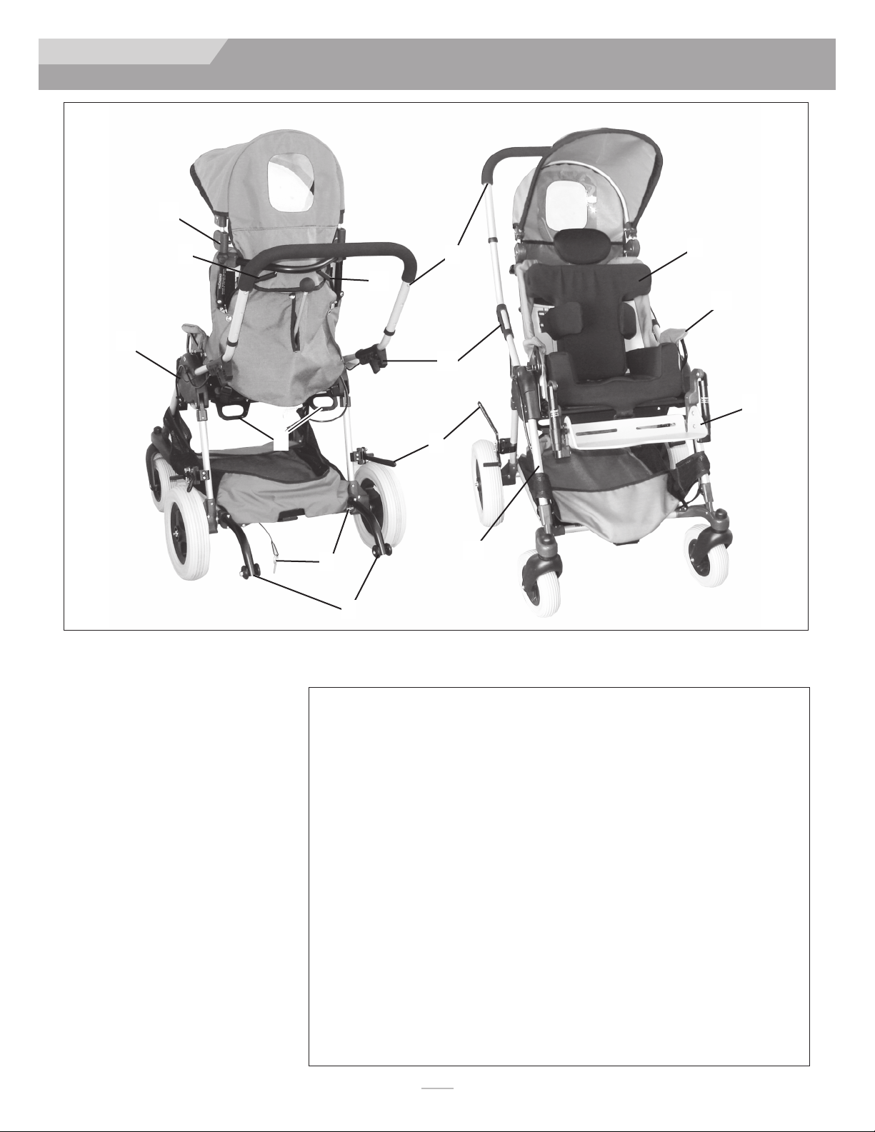
B. GETT NG TO KNOW YOUR DEV CE
WARN NG
Read all instructions before using this product. n particular, you
should be trained in the safe use of this product by your health
care professional.
C. TO REDUCE THE R SK OF AN ACC DENT
WARN NG
1. BEFORE using this device, you should be trained in ts safe
use by your health care professional.
2. Practice transfers until you know your limits and the extent
of your child’s abilities. Always ask if you need to have
someone help you to avoid a fall or tip-over.
3. Be aware that you must develop your own methods for safe
use best suited to your level of function and ability.
4. NEVER try a new maneuver on your own until you are sure
you can do it safely.
5. Get to know the areas where you plan to use your device,
look for hazards and learn how to avoid them.
D.SAFETY CHECKL ST
WARN NG
Before each use of the Early ntervention Device.
1. Parking brake must be adjusted to maintain proper perform-
ance. Always engage the parking brake before transferring a
dependent child.
2. Check that the device rolls easily, and that all parts work
smoothly. Check for noise, vibration, or a change in ease of
use, (they may indicate loose fasteners, or other damage).
3. Repair any problem you may encounter. Your authorized
supplier can help you find and correct any problems.
4. Make sure the tire/axle on both sides are fully engaged and
locked. f they are not locked, the wheel may come off and
cause a fall.
5. Never seat your child in the mobility device until it is fully
unfolded and locked.
6. After adjusting handle length check to make sure that it is
locked at the new length.
7. Always use a pelvic positioning belt when child is seated.
8. Never leave your child unattended.
E. CHANGES AND ADJUSTMENTS
WARN NG
1. If you modify or adjust this chair, it may increase the risk of
a tip-over UNLESS you make other adjustments as well.
2. Consult your authorized supplier BEFORE you modify or
adjust your chair.
3. We recommend that you use anti-tip tubes until you adapt
to the change, and are sure you are not at risk to tip over.
4. Unauthorized modifications by the end-user, dealer or any
other individual, including the use of parts not supplied or
approved by Sunrise may change the chair structure. This
will void the warranty and may cause a safety hazard.
9921700000 Rev. E

6
Z PP E XP RE SS
5. n an accident or sudden stop the rider may be thrown from
the mobility device. Mobility device pelvic positioning belts
will not prevent this and further injury may result from
these belts or straps.
6. NEVER transport this mobility device in the front seat of a
vehicle. This action could risk serious injury or death to the
dependent rider and driver.
7. ALWAYS secure the unoccupied mobility device so that it
cannot roll or shift when being transported in a vehicle.
8. Do not use this product if it has been involved in a motor
vehicle accident. f your device is equipped with the transit
option, refer to Section V . “Transit Option and Use”.
. FOR CAREG VERS
WARN NG
1. Work with the child’s health care professional to learn safe-
ty methods best suited to your abilities and those of your
child.
2. To prevent injury to your back, use good posture and prop-
er body mechanics when lifting, or tilting your child.
3. Remind the dependent to lean back when you tilt the mobil-
ity device backward.
4. When you descend a curb or single step, slowly lower the
mobility device in one easy movement.
5. NEVER leave the dependent child alone.
6. When making adjustments to the mobility device, always
engage the parking brake and lock caster wheels to help
minimize unintended movement.
F. ENV RONMENTAL COND T ONS
WARN NG
1. Your mobility device is designed for use on firm, even sur-
faces such as concrete, asphalt, indoor floors and carpeting.
2. Use extra care if you must use this mobility device on a wet
or slick surface. f you are in doubt, ask for help.
3. Do not operate your mobility device in sand, loose soil or
over rough terrain.
4. Do not use this product in a shower, pool or other bodies
of water.
G.STREET USE
WARN NG
1. When using this device, avoid street use whenever possible.
2. This product should stay in, and obey all legal pedestrian
pathways, and laws that apply to pedestrians.
3. Be alert to the danger of motor vehicles in parking lots.
4. At night, or when lighting is poor, use reflective tape or
clothing for maximum visibility.
5. F you have to cross a road, make eye contact with drivers
before you go forward. When in doubt, yield until you are
sure it is safe.
H. MOTOR VEH CLE SAFETY
WARN NG
1. As indicated on the front cover of this user manual, identify
whether your device has been manufactured with the transit
option installed. f your device is NOT equipped with the transit
option:
2. NEVER use the mobility device seating system as a car seat.
3. ALWAYS move the rider to an approved vehicle seat.
4. ALWAYS secure the rider with proper motor vehicle restraints
VI. WARNINGS: FALLS & TIP-OVERS
B. DRESS NG OR CHANG NG CLOTHES
WARN NG
Your child's weight may shift if you dress your child or change
your child's clothes while they are seated in the mobility device.
To reduce the risk of a fall or tip over while changing clothes or diapers:
• Rotate the front casters until they point forward.
• Engage the parking brake.
C. OBSTACLES
WARN NG
Obstacles and road hazards (such as potholes and broken pavement)
can damage your mobility device and may cause a fall, tip over, or loss
of control. To avoid these risks:
• Scan the area well ahead for danger as you travel with your mobility
device.
• Make sure floor areas ahead are level and free of obstacles.
• nstall a ramp at entry or exit doors. Make sure there is not a drop
off at the bottom of the ramp.
A. CENTER OF BALANCE
WARN NG
Dependent mobility devices are designed for stability and perform-
ance. The point where this device will tip forward, back, or to the
side depends on its center of balance and stability. The center of
balance is also affected by:
• The seat height and seat angle.
• Backrest angle.
• Changes in your child's body position, postures or weight
distribution.
• Pushing the mobility device on a ramp or slope.
• The use of a backpack or other options, and the amount
of added weight.
• The use of a vents, batteries, oxygen and other options, and
the amount of added weight that these options add to the
device.
To maintain the proper center of gravity
and good balance:
• Consult your healthcare advisor and/or supplier to help you
in setting up the mobility device correctly.
• Consult your authorized supplier or healthcare advisor
BEFORE you modify or adjust the mobility device.
V. GENERAL WARNINGS
9921700000 Rev. E

7
Z PP E XP RE SS
D. REACH NG OR LEAN NG
WARN NG
f your child reaches or leans it will affect the center of balance of the mobil-
ity device. This may cause a fall or tip over.
• NEVER allow your child to reach or lean if they must rise up off
their seat for the action.
• f your child must reach, move the mobility device as close as you
can to the object, and rotate the front casters until they are as far
forward as possible.
NOTE– To do this: Move your mobility device past the object that the child
might want to reach, then back up alongside it.
E. RAMPS, SLOPES AND S DEH LLS
WARN NG
Pushing the mobility device on a slope, including ramps or hills, will
change the center of balance. Some safety reminders include:
1. Do not push this product on a slope steeper than 6%. (A 6%
slope means: one foot in elevation for every 16 feet of slope
length).
2. Do not turn or change direction on a slope or ramp.
3. For your child's safety, ramps at home and work must meet
all legal requirements for your location.
4. Always stay in the CENTER of the ramp.
5. Use a ramp with guardrails (or raised borders that are at
least 3" high).
6. Always go straight up and straight down on hills or ramps.
7. Do not stop on a steep slope.
8. Watch for a drop-off at the bottom of a slope or ramp.
9. Do not engage the parking brake to slow or stop your
mobility device.
10. Beware of wet or slippery surfaces, especially on slopes.
11. Do not recline or tilt the shell while going up hills.
12. Ask for help any time you are in doubt of stability.
F. TRANSFERS
WARN NG
1. Work with your health care advisor to learn safe transfer
and lifting methods.
2. Have someone help you until you know how to do a safe
transfer of the dependent on your own.
3. Move your child's mobility device as close as you can to the
location you are transferring to.
4. Rotate the front casters until they point forward.
5. Engage the parking brake before you transfer. This keeps
the device stable during the transfer.
6. When transferring a child into the device, make sure they
are placed as far back onto the seat surface as possible. This
will reduce the risk that the mobility device will tip over
and/or move away from you.
G.NEGOT AT NG A CURB OR S NGLE STEP
WARN NG
Follow the instructions below for descending or climbing a stair or
curb. Do not try to climb a high curb or step more than 4” high,
if the accessory tray, or rear glider platform is installed. Doing so
can risk injury, may cause the device to exceed its balance point
and tip over, and may cause damage to the device.
To descend a curb or single step going FORWARD:
1. Stay at the rear of the mobility device.
2. Several feet before you reach the edge of the curb or step,
tip the device slightly backward. When the device is at its
balance point, carefully step forwards until the rear wheels
reach the edge of the curb or step.
3. Allow the rear wheels to slowly roll down onto the lower
level. Push the chair forward until you are standing on the
lower level.
4. Gently lower front casters to the ground.
To climb a step or curb going BACKWARD:
1. Stay behind the mobility device.
2. Continue backwards until the rear wheels contact the face
of the curb or step. Lift and roll the rear wheels to the top
of the curb.
3. Pull the device backwards until the caster wheels have
cleared the edge of the curb and return the chair to it’s
rolling position.
H. CL MB NG STA RS
WARN NG
1. Do not climb stairs if your mobility device has an accessory
tray installed.
2. Use at least two attendants when moving the occupied
mobility device up stairs.
3. The rider and mobility device should be facing BACKWARD
when moving up the stairs.
4 ALWAYS carry the mobility device by holding the FRAME,
being careful to avoid grabbing the footrest, wheels, tray
parts, and other areas that are meant to detach from the
mobility device.
5. The person at the rear should be in control. He or she
should tilt the mobility device back to its balance point.
6. A second attendant at the front firmly grasps a non-detach-
able part of the front frame and lifts the mobility device up
and over the stair.
7. The attendants should move up one stair at a time until the
landing is reached.
VI. WARNINGS: FALLS & TIP-OVERS
9921700000 Rev. E

8
Z PP E XP RE SS
VII. WARNINGS– COMPONENTS & OPTIONS
. DESCEND NG STA RS
WARN NG
1. Do not descend stairs if your mobility device has an acces-
sory tray installed.
2. Use at least two attendants to move an occupied mobility
device down stairs.
3. Move the mobility device with both the device and rider fac-
ing FORWARD down the stairs.
4. The person at the rear is in control. He or she tilts the
mobility device back to the balance point of the rear wheels
and rolls it to the edge of the top step.
5. A second attendant stands on the third step from the top
and grasps the frame. He or she lowers the device one step
at a time by letting the rear wheels roll over the stair edge.
6. The attendants should move down one stair at a time until
the landing is reached.
J. ESCALATORS
WARN NG
NEVER use this mobility device on an escalator, even with an
attendant.
VI. WARNINGS: FALLS & TIP-OVERS
WARN NG
This early intervention device has been tested and approved using
Sunrise accessories. Any accessory that has not been been
expressly approved by Sunrise Medical will void your warranty,
and may add a safety risk to attendant and child.
A. BASE FRAME
WARN NG
nspect cables and engage/release buttons before every use to
make sure they are in good working condition. Be sure that your
base frame is locked before seating your child.
B. UPPER EXTREM TY SUPPORT TRAY
WARN NG
Before adding or removing a tray to the mobility device be sure to
point front casters to the front of the device and engage parking
brake. This keeps the wheels from rolling when attaching the tray.
The support tray has a weight capacity of 50lbs.
1. Do not lift this product by its tray support arms.
2. ALWAYS make certain that the tray is fully locked into
place after adding it to the dependent mobility device.
C. FASTENERS
WARN NG
Many of the screws, and nuts on this product are considered to be
special high-strength fasteners. They require periodic checks and
maintenence to ensure the safety of both the user and attendant.
1. Most adjustments that require removing hardware should be
done by your Service provider.
2. Only use fasteners provided by an authorized supplier (or
ones of the same type and strength), as indicated by the
markings on the heads.
3. Do not over- or under-tighten fasteners. f screws or nuts
become loose, tighten them as soon as possible.
D.ANT -T P TUBES
WARN NG
Anti-tip tubes can help keep your mobility device from tipping.
Do not remove the anti-tip tubes and always use them in the
down position whenever the base is unfolded.
E. FOOTREST
WARN NG
1. Adjustment of the footbed may cause interference with the
front lower frame in some positions. This interference can
affect the comfort and proper support for the seated
dependent.
2. Avoid putting extra weight on the footbed. The mobility
device may tip forward (or backward if seating system has
been reversed).
3 Never lift this mobility device by the footbeds.
F. T RES AND WHEELS
WARN NG
1. Yearly tire inspection for excessive wear is suggested to
ensure good traction in all types of environments.
2. When installing front or rear wheel/tire assembly, slide the
wheels into the axle opening until the quick release button
pops out, and you hear a click. Your wheel is now fully
engaged and locked.
G.PARK NG BRAKE
WARN NG
Never engage the parking brake to slow or stop this product
when it is moving. To keep the rear wheels from rolling, always
engage the parking brake fully when you transfer your dependent
or the dependent seating system.
H. UNDERCARR AGE STORAGE
WARN NG
This mobility device's storage basket was designed for the addition
of up to 15lbs of additional weight. Excessive weight my cause an
unstable or hazardous condition to exist.
. ACCESSORY TRAYS
WARN NG
The accessory trays should not be used to store excessive weight,
or a piece of equipment that has not been approved for use by
Sunrise Medical. This may cause an unstable or hazardous condi-
tion for the rider or attendant.
9921700000 Rev. E

9
Z PP E XP RE SS
2. f possible and feasible, the occupant should transfer to the
vehicle seat and use the OEM vehicle-installed restraints.
3. The occupant must be facing the front of the vehicle during
transport.
4. Wheelchair Tiedown and Occupant Restraint Systems
(WTORS) must be used.
5. A Wheelchair Tiedown that has been tested in accordance
with SAE J2249 must also be used in any transit situation.
6. The Occupant must be restrained with a vehicle anchored
3-point Belt.
7. Mobility device mounted accessories, such as trays and res-
piratory equipment, and batteries, should be removed, and
secured separately. The optional Xpress vent tray, oxygen
holder, and V pole must also be removed and secured sepa-
rately before using as a seat in a motor vehicle.
8. The occupant must not weigh more than 55lbs. (25 Kg).
9. The location(s) of the front and rear securement points(A) are
marked with a transit point label for clear identification.
10. Use only with WTORS that have been installed in accor-
dance with the manufacturer's instructions and SAE J2249.
Attach WTORS to the securement points(A) in accordance
with the manufacture's instructions and SAE J2249.
J. CANOPY
WARN NG
When using the canopy, make sure that it is secure by checking the
clamps that hold it to the base.
K. SEAT NG SYSTEMS
WARN NG
DO NOT change the seating system, or individual components of
your dependent mobility device unless you have first consulted your
health care professional.
L. PELV C POS T ON NG BELTS
WARN NG
The positioning belt is predominately used to support your posture.
It can also be used to limit slipping and/or sliding that you might
experience when the chair is in motion. The positioning belt is not a
transit rated safety belt and should not be used in the place of a seat
belt while being transported in a motor vehicle. Improper use of
Positioning belts may cause severe injury or death. If you use a
positioning belt, be sure to follow the recommendations in this
section:
1. Make sure the rider does not slide down in the wheelchair
seat. If this occurs, the rider may suffer chest compression or
suffocate due to pressure from the belts.
2. The belts must be snug, but must not be so tight that they
interfere with breathing. You should be able to slide your open
hand, flat, between the belt and the rider.
3. A pelvic wedge or a similar device can help keep the rider from
sliding down in the seat. Consult with the rider’s doctor, nurse
or therapist to find out if the rider needs such a device.
4. Use positioning belts only with a rider who can cooperate.
Make sure the rider can easily remove the belts in an
emergency.
5. NEVER use the positioning belts:
•As a patient restraint. A restraint requires a doctor’s order.
• On a child who is comatose, agitated or is prone to seizures.
•As a motor vehicle restraint. In an accident or sudden stop
the rider may be thrown from the chair. Wheelchair
positioning belts will not prevent this, and further injury may
result from the belts or straps..
M.CUSH ONS
WARN NG
This mobility device's seating was designed for comfort and pos-
tural support. f seating component modifications are necessary,
consult your healthcare advisor.
N. T LT AND RECL NE
WARN NG
Using the tilt or recline adjustments triggers before taking the nec-
essary precautions may effect the balance and stability of your
device. BEFORE making these adjustments you must be aware of
the following:
1. The child must be secure in the device.
2. You must rotate the front casters forward, and engage the
parking brake.
3. ALWAYS make certain that the dependent mobility device is
level and stable before adjusting the tilt and/or recline.
4. ALWAYS support the seating shell when releasing the tilt
trigger.
O.TRANS T OPT ON AND USE
NOTE - The Zippie Xpress has passed transit testing and is considered to
be SO 7176-19 compliant for a dependent child weighing at least
26lbs (12kg) and up to 55lbs (25kg). n transit, the occupant must
be secured within the vehicle and secured in a 3 point harness.
Transit straps should be secured to the front and rear transit
securement points (A).
WARN NG
1. t is recommended that the Zippie Xpress not be used to
transport occupants weighing 25lbs (11kg) or less. Rather,
occupants 25lbs (11kg) or less should be transported using a
suitable rearward facing infant car seat.
321 4
12
A
A
Rear Transit
securement points
Front Transit
securemtnt points
3
Look for this symbol on your wheelchair. t indicates
wheelchair securement points which conform to
ANS /RESNA (1998) V.1 - Section 19 and/or ANS /RESNA
(2012) V.4 WC-19, and SO 7176-19.
If you fail to heed these warnings, damage to your chair, a fall, tip-over or loss
of control may occur and cause severe injury to the rider or others.
9921700000 Rev. E

10
Z PP E XP RE SS
11. The angle of the pelvic belt should be within the preferred zone of 45 to 75 degrees to
the horizontal, or within the optional zone of 30 to 45 degrees to the horizontal (Fig. 4)
12. The pelvic belt should be worn low across the front of the pelvis. Position upper
torso belts over the shoulders. The belt(s) should not be held away from the body by
wheelchair components. Ensure that the belts are not twisted.
14. f a recline angle is required during transport, the chair seat/back should be positioned
at an angle of no more than 30° to the vertical, or the occupant is at risk of injury in
the event of an accident or collision.
15. Attach all occupant restraints in accordance with the manufacturer's instructions and
SAE J2249.
NOTE– To obtain a copy of SAE J2249 “Wheelchair Tiedown and Occupant Restraint Systems for
Use in Motor Vehicles” Please contact:
SAE nternational, 400 Commonwealth Drive
Warrendale, PA 15096-0001
or by phone at (724)-776-4970, or (877) 606-7232
P. TRANS T CONF GURAT ONS
WARN NG
Be sure the device is in one of the configurations below if the occupant must be transported
in a motor vehicle and secured with (WTORS) and the requirements of SAE J3349.
1. For Children over 20lbs, the positioning shell/mobility base unit has been dynamically
tested with the occupant facing forward for a 30 mph (48-km/h) frontal impact test.
The occupant must be facing the front of the vehicle during transport, (See Fig. 5)
2. For children 20lbs and under that cannot be transported in an approved car seat, the
positioning shell/mobility base unit has been dynamically tested with the occupant fac-
ing rearward for a 30mph (48-km/h) frontal impact test. The occupant must be facing
the rear of the vehicle during transport, (See Fig. 6)
5 6
6
4
VII. WARNINGS: COMPONENTS & OPTIONS
5
Front of
Vehicle
Front of
Vehicle
Front of
Vehicle
Front of
Vehicle
FORWARD
FAC NG
REVERSED
FAC NG
9921700000 Rev. E

11
Z PP E XP RE SS
VIII. USE AND MAINTENANCE
A. MA NTENENCE AND SAFETY NOTES
1. Proper maintenance will improve performance and extend
the useful life of your mobility device.
2. Clean the device regularly. This will help you find loose or
worn parts and will make your device easier to use.
3. To protect your investment, have all major service and
repair work done by your supplier.
4. At least every four months, check all screws and knobs for
tightness. f parts are missing, broken, damaged or worn,
then discontinue use of the product until repairs are made,
using factory-authorized parts.
5. Wipe down all plastic components periodically with a solu-
tion of mild soapy water to maintain cleanliness.
6. Hand wash and air-dry the fabric components as needed.
7. Lubricate all moving metal parts with a teflon lubricant only.
NOTE - Using lubricant other than Teflon-based may damage moving parts
8. Check the parking brake lock pin weekly to make sure it
engages smoothly into the wheel hub. This simple check will
insure the safety of the rider. Lubricate with a Teflon
Lubricant when needed.
9. Check and clean the wheel attachment points frequently,
this is a main area that can collect dirt and grime. Debris in
this area can effect the performance and safety of the device.
WARN NG
1. Your device needs regular maintenance for peak perform-
ance and to avoid injury from a device failure, damage or
premature wear.
2. nspect and maintain this device strictly using this Owner’s
manual as a reference.
3. f you detect a problem, make sure to service or repair the
device before putting it back into use.
4. At least once a year, have a complete safety check and serv-
ice of your device performed by your supplier.
B. CLEAN NG
Base Frame Parts:
• Clean with mild soapy water monthly.
Upholstery:
• Hand-wash as needed. Machine wash as needed.
• Drip-dry only. Heat from a dryer may damage fabric.
NOTE - Washing the fabric may decrease fire retardant properties.
C. STORAGE T PS
1. Store your device in a clean, dry area. f you fail to do so,
parts may rust or corrode.
2. Before using your mobility device, make sure it is in proper
working order. nspect and service all items included in this
Manual.
3. f you store this device for more than three months, have it
inspected by a supplier before use.
Weekly
3 Months
6 Months
Annually
RTire inspection (excessive wear,cracks)
RParking brake holds firm (no slipping)
RVisually check for loose hardware
RSecurement and positioning belts
RAxle and axle sleeves (check for debris)
RQuick-release axles (Remove clean)
RCaster tires: (Excessive wear, cracks
RCasters: (level, and move smoothly)
RSeating interface: (check for debris)
RFrame, Folding Mechanism
RUpholstery: (clean and dry)
R Service by Authorized Dealer
Safety & Function Check
D. SAFETY CHECKL ST
NOTE - The user or caregiver should perform these weekly and
monthly checks to maintain the safety of their chair. f an item is
not working properly, please contact your authorized dealer.
9921700000 Rev. E

12
Z PP E XP RE SS
E. REAR WHEEL REMOVAL AND NSTALLAT ON
Remove the Rear wheels to reduce the mobility base storage size.
a. To remove, depress the axle release button (A) in the center of the rear wheel and pull the
whole wheel and axle out of the axle tube.
b. To Reinstall, align the axle with the axle tube end and depress the button while pushing the
axle and wheel assembly inward until it stops. The axle is locked when the release button
pops out, and the axle is effectively locked in place.
WARN NG
Pull on the wheel assembly to verify that it is locked in place. Occasionally, the wheels do not both
snap into place. f this should happen, then swap the wheels to the opposite sides.
F. WHEEL LOCKS
Locking and unlocking the wheel locks
a. To lock the wheel lock, Pull on the black handle (C) until the locking arm (B) is embedded
into the tire about 1/8” and check to insure that the lock has been engaged and the handle is
locked in place.
b. To unlock the wheel lock, press down on the black handle (C) until the locking arm is disen-
gaged from the rear tire.
G.UNFOLD AND FOLD
WARN NG
Zippie dependent mobility devices are designed for stability and performance. When unfolded, the
device must be fully open and locked to avoid injury to the dependent rider. Follow the instruc-
tions for unfolding the device carefully, and double-check that the device is fully locked and the fold
lock-out pin is installed before adding the seating shell and rider.
Unfolding:
a. Unhook the fold retaining strap and store in the tray provided under the seating shell.
b. nsert or rotate the anti-tips (D) into a downward position
c. Place the mobility base on the floor with wheel locks engaged. make sure that the mobility
base fold lock out pin (E) is not inserted into the lock out hole.
d. Lift the handle bar into the locked position, then lift up so that the frame unfolds and locks
into the upright position.
e. nsert the mobility base lock pin (E) into the lockout hole. When inserted into the hole, the
locking pin prevents the rear wheels and axle from folding under the mobility device.
f. f the shell is being installed separately, see the positioning shell installation instructions, in
order to position the shell back, depress the recline lever and pull back. Adjust the legrest,
tilt and optional recline to the appropriate configuration.
7
8
10 11
9
12 13
7
8
9
10
VIII. USE AND MAINTENANCE
A
C
D
11
Locked
Unlocked
Unfold
step 1
B
E
12
Unfold
step 2
13
Unfold
step 3
9921700000 Rev. E

13
Z PP E XP RE SS
Two-stage Folding Frame
1. Rotating the handle into storage position:
WARN NG
The Xpress is not intended to be folded with the seating and/or accessories installed. ALWAYS remove
the child and any extra items prior to any action required to fold the base. Failure to do this may damage
the product, or cause possible injury to the child, and/or attendant.
a. Engage the wheel locks, and remove the child from the device.
b. You may also choose to remove the seating shell at this stage.
c. Activate the trigger handle (B) (Fig.15) and fold the handle (A) downwards until it is fully
lowered against the frame as shown in (Fig. 14).
Two-stage Folding Frame
1. Full compact folding:
The Xpress can fold compactly with the shell installed in the forward facing position.
a. Engage the wheel locks, and remove the child from the device.
b. You may also choose to remove the seating shell at this stage.
c. Elevate the legrests, and tilt the seat to the most forward position.
d. Remove the fold lockout pin (C)
e. Activate the trigger handle (B) and fold the base as shown in (Fig. 17).
f. See (Fig. 18) for frame in fully compact folded position.
14 15
16 17 18
VIII. USE AND MAINTENANCE
14
16
17
15
A
B
C
18
9921700000 Rev. E

14
Z PP E XP RE SS
H. POS T ON NG SHELL NSTALLAT ON
WARN NG
BEFORE installing the seating shell, always check that the mobility device is completely unfolded and
in the locked position, and that all four wheels are locked in place. The seating shell should never
be installed with a seated occupant. Always remember to stabilize the mobility device before per-
forming this action.
• Rotate the front casters until they point forward.
• Engage the wheel lock.
The positioning shell has a pivot post on each side that mounts the shell to the mobility base. The
mobility base has a slot on each side that receives the shell pivot posts. The shell will not install
onto, nor remove from, the mobility base when the base push handle is folded. The positioning
shell may be installed in a child facing forward or rearward position. nstallation is the same either
direction.
nstallation in the forward or reversed direction
a. Place the shell over the top of the mobility base, and squeeze the tilt-in-space (T S) lever (D)
attached to the right side of the shell handle.
b. Align the tilt-in-space guide pins (A) and pivot posts (B) with the mobility base pivot slots (C)
and lower the shell into place.
c. Adjust the legrest, tilt, and optional recline to appropriate configuration.
. POS T ON NG SHELL REMOVAL
WARN NG
BEFORE removing the seating shell, always remove the occupant to a safe location. Failure to do so
may result in injury to the dependent, and/or caregiver. Always remember to stabilize the mobility
device before performing this action.
• Rotate the front casters until they point forward.
• Engage the parking brake.
After removing the occupant:
a. Make sure the seat is in the fully upright position (no recline or tilt), and that the push handle
is in its normal use position before you remove the shell.
b. Squeeze and hold the T S lever (D).
c. Lift the shell vertically from the mobility base.
2019
2221
20
21
19
VIII. USE AND MAINTENANCE
A
22
C
D
Forward
position
Reversed
position
B
9921700000 Rev. E

15
Z PP E XP RE SS
J. T LT N SPACE ANGLE ADJUSTMENT
WARN NG
BEFORE using the tilt adjustment, always check that the mobility device is completely
unfolded and in the locked position, and that all four wheels are locked in place. Be careful
to avoid pulling or crimping any life support tubing that may be attached to the child.
Always remember to stabilize the mobility device before performing this action.
• Rotate the front casters until they point forward.
• Engage the wheel locks.
Tilt adjustment
a. Move to the rear of the device behind the child.
b. Support the seating shell with both hands and squeeze the tilt-in-space lever(A).
Position the shell to the desired tilt angle adjustment. The back support, and seating
support components, including the footrest should move together.
c. Release the handle and gently pull on the seating shell to make sure it is locked in the
new position.
d. This adjustment can change the balance of the device slightly so it is good to check
that there is no danger of tipping with the new setting.
K. H P ANGLE ADJUSTMENT (No recline option)
NOTE - One or more adjustment limiting collars may be attached to the seating system to reduce the
range of available hip angles. they attach to the mechanical lock shaft. Consult your supplier
and therapist for adjustment needs.
Adjustment to recline the back and adjust hip angle.
a. Remove the child from the device for this adjustment.
b. Adjust the hip angle by removing the screw that attaches the frame tube to the back-
shell bracket.
c. Position the back to the desired angle, re-insert the screw and tighten.
d. The lower mounting point of the back is provided with a quick release pin to facilitate
folding of the back.
WARN NG
Be sure that the attachment screw, and quick-release pin are installed and the back is secure
before using the device.
L. RECL NE ADJUSTMENT (Optional)
WARN NG
BEFORE using the recline adjustment, always check that the mobility device is completely
unfolded and in the locked position, and that wheel locks are locked in place. Be careful to
avoid pulling or crimping any life support tubing that may be attached to the child. Always
remember to stabilize the mobility device before performing this action.
• Rotate the front casters until they point forward.
• Engage the wheel locks.
• f equipped with shoulder harness, loosen the shoulder straps to allow room for the
recline.
Recline adjustment
a. Working from the left side of the occupant, grasp the recline adjustment lever (B) while
supporting the shell with your other hand.
b. Squeeze the lever then pull on the back support area. When desired angle adjustment
has been reached, release the handle and gently pull on the seating shell to make sure it
is locked in the new position.
c. This adjustment can change the balance of the device slightly so it is good to check
that there is no danger of tipping with the new setting.
d. f equipped with shoulder harness, re-adjust the straps for proper fit.
23
24
VIII. USE AND MAINTENANCE
24
23
A
B
9921700000 Rev. E

16
Z PP E XP RE SS
M.KNEE ANGLE ADJUSTMENT
WARN NG
Always stabilize the mobility device before performing this action.
• Rotate the front casters until they point forward.
• Engage the parking brake.
The knee angle adjustment can be done with occupant in the device.
a. Be careful to avoid pulling or crimping any life support tubing that may be attached to
the child. This adjustment can create a pinch point, so be careful to remove any
obstruction, and/or clothing that could get stuck in this area.
b. Press down on the thumb activated levers (A) at each side of the footbed/hanger.
and adjust the Knee angle to the desired angle.
NOTE - The levers may not move easily until you have adequately supported the weight of the occu-
pant’s legs.
c. Release the levers and allow the Knee angle to lock into place as you remove the sup-
port from the footbed/hanger.
d. Make sure the levers are properly locked after every adjustment.
N.CANOPY NSTALLAT ON AND ADJUSTMENT
WARN NG
t is always best to make sure the dependent is not seated in the mobility device during the
installation of accessories.
Canopy installation
a. Loosen the two thumbscrews (B) located near the top of the back. They screw into
black couplers on each side.
b. Put the canopy rod ends into the mounting holes, raise or lower the canopy to the
proper height and tighten the thumbscrews.
Canopy adjustment
a. Once installed, you can adjust the canopy angle by pushing it forward or backward
until desired protection is obtained.
b. Lift the front of the canopy all the way up for clearance and access to the child.
c. When canopy is being used with the tilt and recline adjustments, it may be necessary
to angle the canopy either forward or rearward for better clearance with the push
handle.
25
2726
27
VIII. USE AND MAINTENANCE
25
26
27
B
A
9921700000 Rev. E

17
Z PP E XP RE SS NOTES
9921700000 Rev. E
9921700000 Rev. E

18
Z PP E XP RE SS
IX. DEALER SERVICE & ADJUSTMENT
A. POS T ON NG AND GROWTH ADJUSTMENTS
WARN NG
f a change in adjustment is necessary for growth or positioning, a healthcare professional
must be consulted before any changes are made. These adjustments are very important to
the orthopedic and neurological needs of the child. Care should be taken to make sure the
changes are physiologically and medically appropriate. Sunrise Medical suggests that any posi-
tioning or growth adjustments be made by your service provider. Do not make or allow
any of the following adjustments while the child is seated in the mobility device.
TOOLS YOU W LL NEED
To set-up, adjust and maintain your device you will need the following tools:
1. 4mm hex key for some growth adjustments.
2. 5/32 hex key (for headrest collar adjustments)
3. 10mm open end wrench
4. Torque Wrench
f you plan to adjust and maintain this device yourself, Sunrise recommends that you use a
torque wrench.
NOTE - The torque wrench must measure inch-pounds. You may buy a torque wrench and proper
metric sockets from any local hardware store.
n general, positioning and growth adjustments should be done in the following order:
1. Adjust seated area
2. Adjust back support area
3. Adjust pelvic positioning belt
4. Adjust footbed
5. Adjust head support(s)
6. Make other standard and optional adjustments that are needed
7. Check to be sure that all adjustment screws are torqued to specifications
B. SEAT DEPTH ADJUSTMENT
a. Start by determining the proper seat cushion depth.
b. Remove the seat cushion. t is attached with Velcro®.
c. Loosen the seat depth adjustment screws (A) found on each side of the frame from
under the seat base (do not remove).
d. Adjust the depth by sliding the front of the seat pan forward, or backwards.
e. Re-tighten hardware(A) and re-attach the cushion.
C. STANDARD SEAT CUSH ON ADJUSTMENT
The standard seat cushion comes in two seat lengths, short and long. The short seat is 7"
long with capability for adding a 2" growth strip at the back of the cushion. The long seat is
9" long with capability for adding a 2" growth strip at the back of the cushion. Both are
capable of adjustment from 5.5 to 11.5 inches width adjustment by adding or removing
adductor foam pads.
Adjusting the width.
a. Unzip and remove seat cover. Add or remove the same combination of adductor
foam pads to each side of the seat, to achieve the desired width.
b. Re-install the cover over the seat and close the zipper.
Adding growth strip:
a. Unzip seat cover to expose the back edge of the foam cushion.
b. Lift the foam overlay pad at the back of the seat and install the growth strip with
tapered ends down.
c. Place the overlay evenly over the growth strip and close the zipper around the
growth strip.
30
31
31
30
A
9921700000 Rev. E

19
Z PP E XP RE SS
D.CONTOURED SEAT NG CUSH ON ADJUSTMENTS
The contoured seat cushion comes in two lengths: short and long. The short cushion is 7"
long with capability to add either a 1 1/2" or 3" growth strip making the length 8 1/2" or 10"
respectively. The long cushion is 8" long with capability to add either a 1 1/2" or 3" growth
strip making the length 9 1/2" or 11" respectively. These growth strips are added at the
center of the seat cushion.
Adding growth strips
a. Unzip seat cover and fold the top over the front edge to expose the cushion.
b. Lift the foam overlay piece away from the velcro attachment, using care not to tear
the foam.
c. Grasp the rear foam section at the middle and lift it from the velcro attachment.
d. Add the either the 1 1/2" or the 3" growth strip at the back of the front foam
section assuring that the angled edges and sides align.
Note: Never use both growth strips at the same time.
e. Re-attach the rear section assuring the angled edges and sides align.
f. Adjust the adductor wedges as needed and position the foam overlay over the
cushion and attach to the velcro at the rear of the seat.
g. Close the zipper around the cushion and install into the unit.
Cleaning the seat cover
a. Unzip the cover along the edge.
b. Remove the cushion assembly from the velcro attachment inside the cover.
c. The fabric seat cover should be hand washed in laundry soap, thoroughly rinsed with
clean water and air dried.
d. The foam cushion pieces may be wiped down with soap and water. Always be sure
they are completely dry before replacing the fabric cover.
e. Place the cushion into the fabric cover onto the velcro with the front edge of the
cushion aligned with the front edge of the cover.
f. Pull the cover over the cushion and close the zipper around the cover.
E. STANDARD CUSH ON W THOUT LATERAL H P SUPPORT
The standard Cushion without-Lateral Hip Supports comes in two seat lengths, short and
long. The short seat is 7" long with capability for adding a 2" growth strip at the back of the
cushion. The long seat is 9" long with capability for adding a 2" growth strip at the back of
the cushion.
F. BACK POS T ON NG PLATE HE GHT ADJUSTMENT
Adjusting the back positioning plate
a. Open the exterior back panel fabric sections on the outside to expose the back
growth slots and adjustment screws.
b. Loosen the screws through the access holes (A) behind the back plate on each side,
adjust to proper height.
c. Tighten both adjustment screws and make sure the back plate is locked in position.
G.BACK CUSH ON HE GHT ADJUSTMENT
a. Fit the back cushion to the positioning plate at proper height.
b. Add appropriate back cushion growth inserts if a gap is present at the bottom of the
back cushion.
32 33
34 34
IX. DEALER SERVICE & ADJUSTMENT
32
33
A
9921700000 Rev. E

20
Z PP E XP RE SS
H. FOOTBED ADJUSTMENTS
Height Adjustment
Two telescoping tube sections adjust and lock to control footbed height.
a. dentify adjustment screw locations on the rear side of the footbed hanger.
b. Loosen upper screw on each side of the footbed hanger.
c. Slide the footbed up or down to proper height.
d. Tighten both screws.
e. Repeat procedure using lower screw in step 2 if additional range is required.
Angle Adjustment
The footbed has two screws that fit into a series of holes in the footbed sides and two
more that allow footbed rotation.
a. Remove the footbed angle adjustment screw on each side of the footbed.
b. Adjust the footbed to proper angle and align nearest adjustment holes with the
footbed couplers.
c. nstall adjustment screws through footbed and into footbed coupler to maintain
proper footbed angle.
Lengthening the Footbed for Maximum Lower Leg Length Adjustment
The foot bed is designed so that the brackets on the ends of the telescoping tubes can be
reversed to add approximately 3 1/2" of leg length adjustment.
a. Remove the footbed from the telescoping tubes by unscrewing the four button head
screws (A) on the inside of the footbed.
b. Remove the screw from each bracket by backing it out far enough to allow the
bracket to slip off the end of the tube.
c. Flip the bracket over and replace it on the end of the tube being careful to align the
screw with the same hole in the end of the tube.
d. Tighten the mounting screw so it goes through the hole and tightens up against
the bracket.
e. Replace the footbed onto the brackets assuring the same angle adjustment is
achieved.
. PELV C POS T ON NG BELT ADJUSTMENTS
Length Adjustment
a. Remove any belt twists and place the belts outside of the seating area.
b. Engage wheel locks, seat the child, and snap the pelvic positioning belt ends together.
c. Adjust belt length to provide a snug fit. The adjuster is to the child's left.
Position Adjustment
For the standard seat configuration the belt is always adjusted to the rear most point
(approximately 45°). When the contour seat cushion is used, the belt may be adjusted for-
ward to achieve an adjustment of up to 90°.
a. Loosen the attachment screw (B) one or two turns to allow the belt anchor point to
slide in the slot.
b. Move the belt to the desired adjustment position (leave in the rear most position
when the standard seat configuration is used).
c. Tighten the screw.
NOTE - nstall the nylon web strap wraps under the tube, beside the seat base, and back over the top
of the tube. This keeps the belt in the outer most position so it does not interfere with the
seat cushion.
35
38
36
37
IX. DEALER SERVICE & ADJUSTMENT
35
36
37
38
B
A
9921700000 Rev. E
Table of contents
Other Zippie Wheelchair manuals

Zippie
Zippie Pluton 1 Manual

Zippie
Zippie ZM-310 User manual

Zippie
Zippie RS User manual

Zippie
Zippie X'CAPE User manual

Zippie
Zippie IRIS Installation and operation manual

Zippie
Zippie Salsa M Manual

Zippie
Zippie RS User manual

Zippie
Zippie YOUNGSTER 3 Manual

Zippie
Zippie X'CAPE User manual

Zippie
Zippie Simba Manual

Zippie
Zippie VOYAGE User manual

Zippie
Zippie IRIS User manual

Zippie
Zippie ZONE User manual

Zippie
Zippie Neptune Manual

Zippie
Zippie Zippie Z-Bop User manual

Zippie
Zippie IRIS User manual

Zippie
Zippie Salsa R2 User manual

Zippie
Zippie Neptune 2 Manual

Zippie
Zippie X’CAPE WC-19 User manual

Zippie
Zippie ZONE User manual