Zippie RS User manual

Owner's Manual
Manuel d’utilisation
Handleiding
Zippie RS
Manual Wheelchair
Fauteuil roulant manuel
Handbewogen rolstoelen
000690689.02

IF YOU ARE VISUALLY IMPAIRED, THIS DOCUMENT CAN BE VIEWED IN PDF
FORMAT AT WWW.SUNRISEMEDICAL.CO.UK.
SI VOUS SOUFFREZ DE DÉFICIENCE VISUELLE, CE DOCUMENT PEUT ÊTRE
CONSULTÉ EN FORMAT PDF SUR WWW.SUNRISEMEDICAL.FR
ALS U VISUEEL GEHANDICAPT BENT KAN DIT DOCUMENT OOK WORDEN
GELEZEN IN PDF-FORMAAT OP: WWW.SUNRISEMEDICAL.NL
Description du fauteuil
SUNRISE MEDICAL est certié ISO -9001, une norme qui garantit la qualité des produits à toutes les étapes, de la conception à la produc-
tion, en passant par la recherche et le développement. Ce produit est conforme aux directives de la Communauté européenne. Les options
ou accessoires illustrés sont disponibles moyennant un coût supplémentaire.
FR
Wheelchair Components
We at SUNRISE MEDICAL have been awarded the ISO-9001 certicate, which afrms the quality of our products at every stage, from R & D to
production. This products meet the requirements in accordance with EC guidelines. Options or accessories shown are available at extra cost.
EN
Rolstoelonderdelen
SUNRISE MEDICAL heeft het ISO 9001 certicaat toegekend gekregen, een bewijs van de kwaliteit van onze processen in elk stadium,
vanaf het onderzoek en de ontwikkeling tot de productie. Deze producten voldoen aan de eisen in overeenstemming met de EG-richtlijnen.
Getoonde opties en accessoires zijn tegen betaling verkrijgbaar.
NL

1
12
11
10
9
8
7
6
5
4
3
2
1.Drum Brake Levers
2.Tilt Levers
3.Push Handle
4.Backpost
5.Side Guard
6.Seat Plate
7.Centre Mount Footplate
8.Fork
9.Castor
10.Frame
11.Rear Wheel
12.Drum Brake
1.Manettes pour frein à tambour
2.Leviers de bascule
3.Poignée
4.Montant du dossier
5.Protège-vêtements
6.Plaque d’assise
7.Palette centrale
8.Fourche
9.Roue avant
10.Châssis
11.Roue arrière
12.Frein à tambour
1.Trommelremhendels
2.Kantelhendels
3.Duwhandvat
4.Rugsteun
5.Zijkanten
6.Zitting
7.Centraal gemonteerde voetplaat
8.Vork
9.Zwenkwiel
10.Frame
11.Rear Wheel
12.Trommelrem

mm °kg
1450
900
630
530
1450
800
390
100
520
430
450
375
310
220
540
485
400
300
MAX.
MIN.
750 440
300
MAX.
MIN.
10O
0O
10O
0O
10O
0O
MAX.
MIN.
+40O
-5O
+30
0O
+90O
0O
MAX.
MIN.
22
14
26
18
125
---
MAX.
MIN.
2,1

20 Nm
30 Nm
25 Nm
25 Nm
30 Nm
3 Nm
30 Nm
3 Nm
7 Nm
7 Nm
3 Nm 10 Nm
3 Nm
7 Nm
25 Nm
5 Nm
7 Nm
M5 = 5,0 Nm
M6 = 7,0 Nm
M8 = 10,0 Nm Nm

cm
cm
4
3
2
1
6” 7” 8”
123 2 43 X X
123 1 44 X X
138 2 45 46 -
138 1 46 47 49
174 4 X X 48
174 3 47 48 50
174 2 48 50 51
174 1 49 / 50 51 52

ENGLISH
7
Zippie RS Rev.1.0
Foreword
Dear Customer,
We are very pleased that you have decided in favour of a high-
quality SUNRISE MEDICAL product.
This Owner’s manual will provide numerous tips and ideas so
that your new wheelchair can become a trustworthy and reliable
partner in your life.
For Sunrise Medical, it is very important that we have a good
relationship with our customers. We like to keep you up-to-date
about new and current developments at our company. Keeping
close to our customers means: fast service, as little red tape as
possible, working closely with customers. When you need
replacement parts or accessories, or if you just have a question
about your wheelchair – we are there for you.
We want you to be satisfied with our products and service. At
Sunrise Medical we are constantly working to develop our
products further. For this reason, changes can occur in our
palette of products with regard to form, technology, and
equipment. Consequently, no claims can be construed from the
data or pictures contained in this Owner’s manual.
The management system of SUNRISE MEDICAL is certified
to EN ISO 9001, ISO 13485 and ISO 14001.
As the manufacturer, SUNRISE MEDICAL,
declares that the lightweight wheelchairs
conform to the 93/42/EEC / 2007/47/EEC
guideline.
Please contact your local, authorised SUNRISE MEDICAL
dealer if you have any questions regarding the use,
maintenance or safety of your wheelchair.
In case there is no authorised dealer in your area or you have
any questions, contact Sunrise Medical either in writing or by
telephone.
Sunrise Medical
Thorns Road
Brierley Hill
West Midlands
DY5 2LD
England
Phone: 0845 605 66 88
Fax: 0845 605 66 89
www.SunriseMedical.co.uk
Use
This base is designed to accept seat shells.
It is suitable for children and adolescents.
The maximum weight limit includes the user and the weight of
any accessories fitted to the wheelchair.
The maximum user weight is marked on the serial number label
that is affixed to the stabiliser bar below the seat.
Warranty can only be taken on if the product is used under the
specified conditions and for the intended purposes.
The expected life of the wheelchair is 5 years.
Please DO NOT use or fit any 3rd party components to the
wheelchair unless they are officially approved by Sunrise
Medical.
Area of application
The variety of fitting variants as well as the modular design
mean that it can be used by those who cannot walk or have
limited mobility because of:
• Paralysis
• Loss of extremity (leg amputation)
• Extremity defect deformity
• Joint contractures/joint injuries
• Illnesses such as heart and circulation deficiencies,
disturbance of equilibrium or cachexia as well as for elderly
people who still have strength in the upper body.
When considering provision, please also note the body size,
weight, physical and psychological constitution, the age of the
person, living conditions and environment.
Operating Conditions
The wheelchair can be used indoors as well as outdoors in self-
propelled or attendant configurations, on dry, firm, relatively
smooth surfaces. It is not recommended for use in a storm,
torrential rain, snow and ice or other extreme weather
conditions.
DO NOT USE YOUR WHEELCHAIR UNTIL THIS
MANUAL HAS BEEN READ AND UNDERSTOOD.
DANGER!
• Do not fit any unauthorised electronic equipment.
• Do not fit powered or mechanically operated mobility devices,
drives, hand-bike or any other device that changes the
intended use or the structure of the wheelchair.
• Any combination with other medical devices requires approval
directly from Sunrise Medical.

ENGLISH
8Zippie RS Rev.1.0
3.1 Denitions of words used in this manual
Word Definition
DANGER!
Advice to the user of Potential Risk
of serious injury or death if the
advice is not followed
WARNING! Advice to the user of a potential risk
of injury if the advice is not followed
CAUTION!
Advice to user that potential
damage to equipment may occur if
the advice is not followed
NOTE: General advice or best practice
Reference To Additional
Documentation
NOTE:
Please keep a note of your local service agent’s address
a n d t e l e p h o n e n u m b e r i n t h e s p a c e p r o v i d e d .
In the event of a breakdown, contact them and try to give
all relevant details so they can help you quickly.
Dealer signature and stamp
Definitions
NOTE:
The wheelchairs shown and described in this user guide
may not correspond in every detail exactly to your own
model. However, all instructions are completely relevant,
regardless of possible detail differences.
The manufacturer reserves the right to alter without
notice any weights, measurements or other technical
data shown in this manual. All figures, measurements
and capacities shown in this manual are approximate,
and do not constitute specifications.
Table of Contents
Denitions 8
1.0 General safety notes and driving limits 9
2.0 Warranty 11
3.0 Transportability 12
4.0 Handling 14
5.0 Set-up and Adjustment 14
6.0 Brakes 15
7.0 Footrests 16
8.0 Castors 17
9.0 Seating and Positioning 18
10.0 Sideguards 20
11.0 Pelvic Restraint Belt 20
12.0 Tyres and Mounting 22
13.0 Technical Data 22
14.0 Name Plate 22
15.0 Maintenance and care 23
16.0 Trouble shooting 23
17.0 Disposal / recycling of materials 23

ENGLISH
9
Zippie RS Rev.1.0
1.0 General safety notes and driving limits
The engineering and construction of this wheelchair has been
designed to provide maximum safety. International safety
standards currently in force have either been fulfilled or
exceeded in parts. Nevertheless, users may put themselves at
risk by improperly using their wheelchairs. For your own safety,
the following rules must be strictly observed.
Unprofessional or erroneous changes or adjustments increase
the risk of accident. As a wheelchair user, you are also part of
the daily traffic on streets and pavements, just like anyone else.
We would like to remind you that you are therefore also subject
to any and all traffic laws.
Be careful during your first ride in this wheelchair. Get to know
your wheelchair.
Before each use, the following should be checked:
• Quick-release axles on the rear wheels
• Tyres, tyre pressure and wheel locks.
Before changing any of the adjustments of this wheelchair, it is
important to read the corresponding section of the user’s
manual.
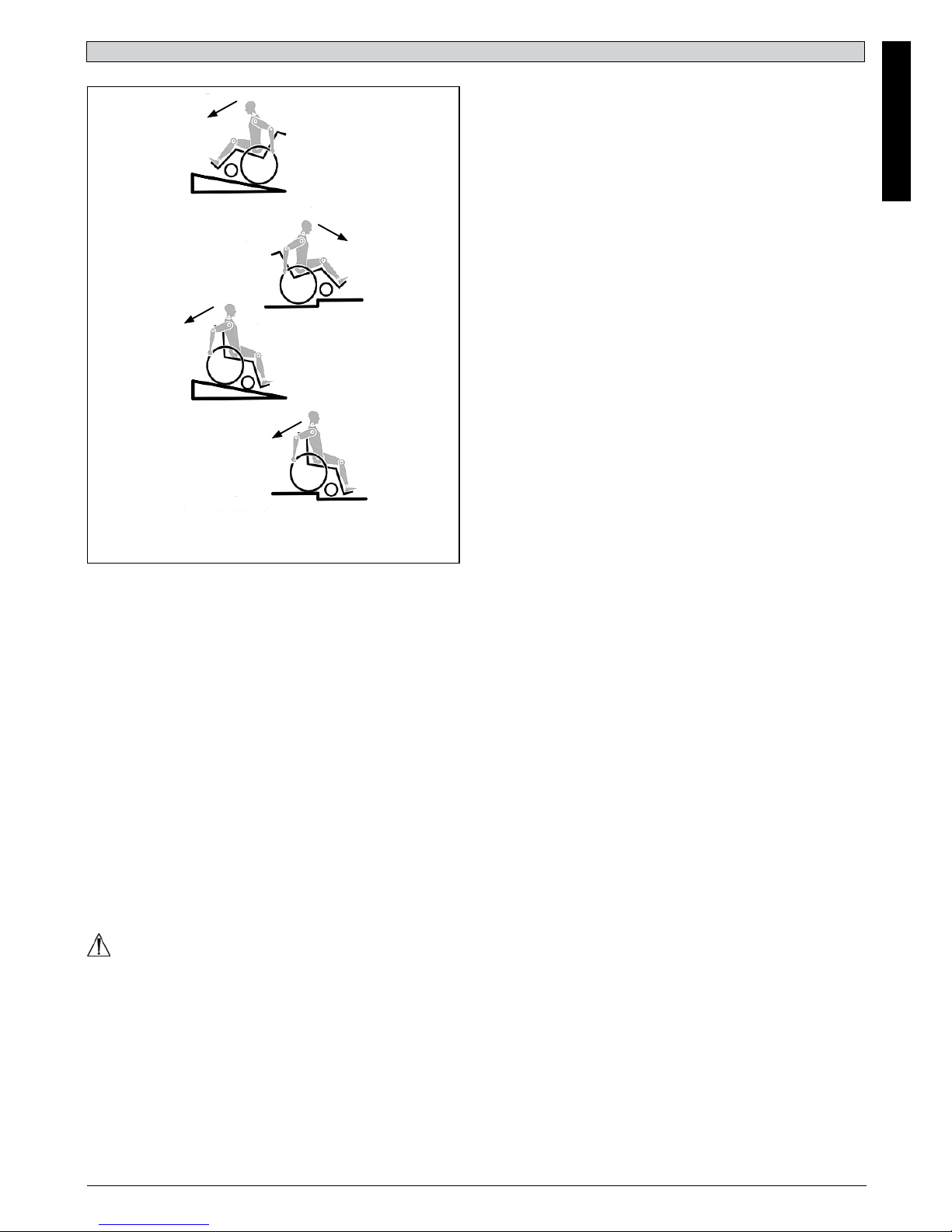
It is possible that potholes or uneven ground could cause this
wheelchair to tip over, especially when riding uphill or downhill.
When riding over a step or up an incline frontally, the body
should be leaning forward.
DANGER!
• NEVER exceed the maximum load of 125 kg, for driver plus
any items carried on the wheelchair. If you exceed the
maximum load, this can lead to damage to the chair, or you
may fall or tip over, lose control and may lead to serious injury
of the user and other people.
• To avoid falls and dangerous situations, you should first
practice using your new wheelchair on level ground with good
visibility.
• This wheelchair should be used exclusively to convey one
person at a time. Any other use does not comply with the
intended purpose.
• When getting on or off the wheelchair, do not use the foot-
boards. These should be flipped up beforehand and swung to
the outside as far as possible.
• Depending on the diameter and setting of the castors, as well
as the centre of gravity setting of the wheelchair, the castor’s
may begin to wobble at high speeds. This can lead to the
castor’s being blocked and the wheelchair may tip over.
Therefore, please make sure that the castor’s are adjusted
correctly (see the Chapter “Castor’s”).
• In particular, do not travel on an incline without brakes, travel
at a reduced speed. At higher speeds, depending on the
configuration and/or physique/physical capabilities of the user,
there may be unexpected castor wobble. This can lead to
injury of the user.
• Explore the effects of changing the centre of gravity on the
behaviour of the wheelchair, for example on inclines, slopes,
all gradients or when overcoming obstacles. Do this with the
secure aid of a helper. We recommend that novice users use
anti-tip tubes.
• Anti-tip tubes should prevent the chair tipping over backwards
unintentionally. Under no circumstances should they take the
place of transit wheels, and be used to transport a person in a
wheelchair with the rear wheels removed.
• With extreme settings (e.g. rear wheels in the most forward
position) and less than perfect posture, the wheelchair may tip
over even on a level surface.
• Do not hang heavy items such as shopping bags or
backpacks, on the push handles, head rest or backrest of the
wheelchair.
• These can change the tipping point and there is a risk of
tipping backwards.
• When reaching for objects (which are in front of, to the side or
behind the wheelchair) make sure that you do not lean too far
out of the wheelchair, as if you change the centre of gravity
there is a risk of tipping or rolling over.
• Only use your wheelchair properly. For example, avoid
travelling against an obstacle without braking (step, kerb edge)
or dropping down gaps.
• Only attempt stairs with the help of an attendant. There is
equipment available to help you, e.g. climbing ramps or lifts,
please use them. If there is no such equipment available, then
the wheelchair must be tipped and pushed over the steps (2
helpers).
• In general, any anti-tip tubes fitted must be set beforehand, so
that they cannot touch the steps, as otherwise this could lead
to a serious tumble. Afterwards the anti-tip tubes must be set
back to their correct position.
• When using the lifting ramp make sure that the anti-tip tubes
fitted are positioned outside the danger area.
• Secure your wheelchair on uneven ground or when
transferring (e.g. into a car) by using the wheel locks.

ENGLISH
10 Zippie RS Rev.1.0
DANGER!
CHOKING HAZARD – This mobility aid uses small parts which
under certain circumstances may present a choking hazard to
young children.
NOTE:
• The effect of the knee-lever brake as well as the general
driving characteristics are dependant on tyre pressure. The
wheelchair is significantly lighter and easier to manoeuvre
when the rear wheels are pumped up correctly and both
wheels have the same pressure.
• Make sure that your tyres have sufficient tread!
• Please note that you are subject to any and all traffic laws
when driving in public traffic.
• When it is dark, please wear light clothing or clothing with
reflectors, so that you can be seen more easily. Make sure
that the reflectors on the side and back of the wheelchair are
clearly visible. We would also recommend that you fit an active
light.
• Always be careful with your fingers when working or adjusting
the wheelchair!
The products shown and described in this manual may not be
exactly the same in every detail as your own model. However,
all instructions are still entirely relevant, irrespective of detail
differences.
The manufacturer reserves the right to alter without notice any
weights, measurements or other technical data shown in this
manual. All figures, measurements and capacities shown in this
manual are approximate and do not constitute specifications.
Lifetime
The expected lifetime of this product is 5 years.
• Before setting off, check that your tyre pressure is correct. For
rear wheels it should be at least 3.5 bar ( 350 k Pa). The max.
Pressure is indicated on the tyre. The knee-lever brakes will
only work if there is sufficient tyre pressure and if the correct
setting has been made (see the Chapter on “Wheel locks”).
The wheel locks are not intended to brake your wheelchair.
They are only there to ensure that your wheelchair does not
begin rolling unintentionally. When you stop on uneven
ground, you should always use the wheel locks to prevent
such rolling. Always apply both wheel locks; otherwise, your
wheelchair could tip over.
• Always make use of elevators and ramps. If these are not
available, you should request the help of an attendant. They
should only grip the wheelchair at securely mounted parts. If
anti-tip tubes are fitted these must be folded away. A
wheelchair should never be lifted with an occupant; it should
only be pushed.
• If the seat and back plate are damaged, you must replace
them immediately.
• Do not lift or carry the wheelchair by the back tubes or the
push handles.
• Do not fit any unauthorised electronic equipment, powered or
mechanically operated mobility drives, hand-bike or any other
device that changes the intended use or the structure of the
wheelchair. Any combination with other medical devices
requires the approval of Sunrise Medical.
• Be careful with fire, in particular with burning cigarettes.
• If and whenever possible, during a journey in a specially fitted
vehicle for disabled people, vehicle occupants should use the
seats in the vehicle and the appropriate restraint system. This
is the only way to ensure that occupants will have the
maximum protection if there is an accident. When using safety
elements offered by SUNRISE MEDICAL and using a
specially designed safety system, lightweight wheelchairs can
be used as a seat when being transported in a specially fitted
vehicle. (See the Chapter on “Transportation”).
• Always make sure that the quick-release axles on the rear
wheels are set properly and lock in. If the button on the quick-
release axle is not pressed in, the rear wheel cannot be
removed.
• In particular when using lightweight metal hand rims, fingers
will easily become hot when braking from a high speed or on
long inclines.
• If the wheelchair is subject to direct sunlight for a long period
of time, then parts of the wheelchair (e.g. frame, leg rests,
brakes and side guard) may become hot (>41°C).
• To avoid hand injuries do not grab in between the spokes or
between the rear wheel and wheel lock when driving the
wheelchair.
• Do not use the wheelchair on slopes > 10°.
• The Dynamic safe slope is dependent on the chair
configuration, the users abilities and the style of riding. As the
users abilities and style of riding cannot be predetermined
then the max safe slope cannot be determined. Therefore this
must be determined by the user with the assistance of an
attendant to prevent tipping. It is strongly recommended that
inexperienced users have Ant-tips fitted. Do not use your
wheelchair on muddy or icy ground. Do not use your
wheelchair where pedestrians are not allowed.
• With all moving parts there is a natural risk of finger traps.
Please handle with care
• The wheelchair should not be used in heavy rain, snow,
slippery, or unsound surfaces. Do not use the wheelchair in
hazardous environments.

ENGLISH
11
Zippie RS Rev.1.0
2.0 Warranty
Guarantee
THIS IN NO WAY AFFECTS YOUR STATUTORY RIGHTS.
Warranty conditions
1) The repair or replacement must be carried out by an
authorised Sunrise Medical dealer/service agent.
2) To apply the warranty conditions, should your produce
require attention under these arrangements, notify the
designated Sunrise Medical service agent immediately giving
full information about the nature of the difficulty. Should you be
operating the product away from the locality of the designated
Sunrise Medical service agent work under the "Warranty
Conditions” will be carried out by any other service agent
designated by the manufacturer.
3) Should any part of the wheelchair require repair or
replacement, as a result of a specific manufacturing or material
defect, within 24 months, (5 years on frame and cross-brace),
from the date on which the possession of the product was
transferred to the original purchaser, and subject to it remaining
within that ownership, the part or parts will be repaired or
replaced completely free of charge if returned to the authorised
service agent.
NOTE: This guarantee is not transferable.
4) Any repaired or replaced part will benefit from these
arrangements for the balance of the warranty period applicable
to the wheelchair.
5) Parts replaced after the original warranty has expired are
covered for a further 12 months.
6) Items of a consumable nature will not generally be covered
during the normal warranty period, unless such items have
clearly suffered undue wear as a direct result of an original
manufacturing defect. These items include amongst others
upholstery, tyres, inner tubes, and similar parts.
7) The above warranty conditions apply to all product parts for
models purchased at full retail price.
8) Under normal circumstances, no responsibility will be
accepted where the product has required repair or replacement
as a direct result of:
a) The product or part not having been maintained or serviced
in accordance with the manufacturer’s recommendations, as
stated in the Owner`s Manual and / or Service Manual. Failing
to use only the specified original equipment parts.
b) The product or part having been damaged by neglect,
accident or improper use.
c) The product or part having been altered from the
manufacturer’s specifications, or repairs having been attempted
prior to the service agent being notified.
d) If the product has corrosion due to incorrect maintenance

ENGLISH
12 Zippie RS Rev.1.0
3.0 Transportability
DANGER!
There is a risk of serious injury or death if this if this advice is
ignored!
Transportation of your wheelchair within a vehicle:
A wheelchair secured in a vehicle will not provide the equivalent
level of safety and security as a vehicle seating system. It is
always recommended that the user transfers to the vehicle
seating. It is recognised that this is not always practical for the
user to be transferred and in these circumstances, where the
user must be transported whilst in the wheelchair, the following
advice must be followed:
1. Confirm that the vehicle is suitably equipped to transport a
passenger in a wheelchair, and ensure the method of access/
egress is suitable for your wheelchair type. The vehicle should
have the floor strength to take the combined weight of the user,
the wheel chair and accessories.
2. Sufficient space should be available around the wheelchair to
enable clear access to attach, tighten and release the
wheelchair and occupant tie down restraints and safety belts.
3.The occupied wheelchair must be located in a forward facing
position and secured by the wheelchair tie down and occupant
restraint straps (WTORS tie downs meeting the requirements of
ISO 10542 or SAE J2249) in accordance with the WTORS
manufacturer’s instructions.
4. The wheelchair’s use in other positions within a vehicle has
not been tested e.g. transportation in a side facing position must
not be carried out under any circumstances (Fig. A).
5. The wheelchair should be secured by a Tie Down Restraint
system, conforming to ISO 10542 or SAE J2249 with non-
adjustable front straps and adjustable rear straps, which
typically use Karabiner clips/S hooks and tongue and buckle
fittings. These restraints generally comprise of 4 individual
straps that are attached to each corner of the wheelchair.
6. The tie-down restraints should be fitted to the main frame of
the wheelchair as indicated in the diagram on the following
page, and not to any attachments or accessories, e.g. not
around the spokes of wheels, brakes or footrests.
Fig.A
7. The tie–down restraints should be attached as close as
possible at an angle of 45 degrees and tightened securely in
accordance with the manufacturer’s instructions.
8.Alterations or substitutions must not be made to the
wheelchair securing points or to structural and frame or
components without consulting the manufacturer. Failure to do
so will invalidate the ability of a Sunrise Medical wheelchair to
be transported within a vehicle.
9. Both pelvic and upper torso restraint belts must be used to
restrain the occupant to reduce the possibility of head and
chest impacts with the vehicle components and serious risk of
injury to the user and other vehicle occupants. (Fig B) The
upper torso restraint belt should be mounted to the vehicle “B”
pillar - failure to do so will increase the risk of serious
abdominal injuries to the user.
10. A head restraint suitable for transportation (see label on
headrest) must be fitted and suitably positioned at all times
during transportation.
11. Postural supports (lap straps, lap belts) should not be used
or relied on for occupant restraint in a moving vehicle unless
they are labelled as meeting the requirements specified in ISO
7176-19:2001 or SAE J2249.
12. The safety of the user during transportation depends upon
the diligence of the person securing the tie-down restraints and
they should have received appropriate instructions and/or
training in their use.
13. Wherever possible remove and stow safely away from the
wheelchair all auxiliary equipment, for example:
Crutches, Loose cushions and Tray Tables.
14. Articulating/elevating leg rest should not be used in the
elevated position when the wheelchair and user are being
transported and the wheelchair is restrained using Wheelchair
Transport and Occupant Restraints.
15. Reclining backrests should be returned to an upright
position.
16. The manual brakes must be firmly applied.
17. Restraints should be mounted to the vehicle “B” pillar and
should not be held away from the body by wheelchair
components such as armrest or wheels.
Fig.B

ENGLISH
13
Zippie RS Rev.1.0
Occupant Restraints Instruction:
1. The pelvic restraint belt must be worn low across the front of
the pelvis so that the angle of the pelvic belt is within the
preferred zone of 30 to 75 degrees to the horizontal.
A steeper (greater) angle within the preferred zone is desirable
i.e. closer to, but never exceeding 75degrees. (Fig C)
2. The upper torso restraint belt must fit over the shoulder and
across the chest as illustrated Fig d and e
Restraint belts must be adjusted as tightly as possible
consistent with user comfort.
Restraint belt webbing must not be twisted when in use.
The upper torso restraint belt must fit over the shoulder and
across the shoulder as illustrated in Fig D and E.
3. The attachment points to the chair are the inner front side
frame just above the castor, and the rear side frame. The straps
are fitted around the side frames at the intersection of the
horizontal and vertical frame tubes. (See Figs G-H-I).
4. The tie down symbol (Fig F) on the wheelchair frame
indicates the position of the wheelchair restraint straps. The
straps are then tensioned after the front straps have been fitted
to secure the wheelchair.
DANGER!
USER WEIGHT LESS THAN 22 kg (48 lb 8.0 oz)
When the user being transported is a child, less than 22Kg mass
and the vehicle involved has less than eight (8) seated
passengers it is recommended that they be transferred to an
UNCE Regulation 44 compliant child restraint system (CRS).
This type of restraint system provides a more effective occupant
restraint system than the conventional 3 point occupant restraint
system and some CRS systems also include additional postural
supports to assist in maintaining the position of the child when
seated.
Parents or care providers may consider the option, in some
circumstances, for their child is to remain in their wheelchair
whilst in transport due to the level of posture control and comfort
provided by the set up in the wheelchair.
We would recommend in such circumstances that a risk
assessment be carried out by your healthcare professional and
relevant competent persons.
Transportability – positioning of wheelchair tie down
restraints on wheelchair
Position of the front wheelchair tie down restraint and the tie
down position, (Fig.G).
Position of the rear wheelchair tie down restraint and the tie
down position on the wheelchair, (Fig.H).
The wheelchair secured with front and rear wheelchair tie down
restraints, (Fig.I).
DANGER!
The base is only permitted as a seat in the car, if the mounted
seat shell is tested by ISO 16840-4.
Fig.D
Fig.E
Fig.C
PREFERRED
ZONE
Fig.F
Transportability
Fig.H
Fig.G Fig.I

ENGLISH
14 Zippie RS Rev.1.0
4.0 Handling
Quick-Release Axles for Rear Wheels (Fig. 4.1)
The rear wheels are equipped with quick-release axles. The
wheels can thus be installed or removed with out using tools. To
remove a wheel, simply depress the quick-release button on the
axle (1) and pull it out.
CAUTION!
Hold the quick-release button on the axle depressed when
inserting the axle into the frame to mount the rear wheels.
Release the button to lock the wheel in place. The quick-release
button should snap back to its original position.
Tipping Tubes (Fig. 4.2)
Tipping tubes are used by attendants to tip a wheelchair over
an obstacle. Simply step on the tube to push a wheel chair, for
example, over a curb or step.
Fig. 4.2
5.0 Set-up and Adjustment
ANTI-TIP TUBES- REAR (Fig.5.1 - 5.3).
Anti-tip tubes are recommended for all wheelchairs.
NOTE: Use a torque setting of 96 in.-lbs. when setting-up anti-tip
tubes.
1. Inserting Anti-Tip Tubes Into Receivers
a. Press the rear anti-tip release pin (A) on the anti-tip tube so
that both release pins are drawn inside.
b. Insert the anti-tip tube into the receiver (B).
c. Turn the anti-tip tube down until release pin protrudes through
the receiver mounting hole.
d. Insert second anti-tip tube the same way.
2. Turning Anti-Tip Tubes Up
Turn anti-tip tubes up when being pushed by attendant,
overcoming obstacles or climbing curbs.
a. Press the rear anti-tip tube release pin (A).
b. Hold pin in and turn anti-tip tube up (C).
c. Release pin.
d. Repeat with second anti-tip tube.
e. Remember to return anti-tip tubes to down position after
completing maneuver.
3. Adjusting Anti-Tip Tube Wheel
The anti-tip tube wheels may have to be raised or lowered to
achieve proper ground clearance (1-1/2” to 2”).
a. Press the anti-tip wheel release pin (D) so that the release pin
is drawn inside.
b. Raise or lower to one of the three or four pre-drilled holes.
c. Release pin (D).
d. Adjust the second anti-tip tube wheel the same way. Both
wheels should be at exactly the same height.
Fig. 5.1
Fig. 5.2
Fig. 5.3
1
Fig. 4.1

ENGLISH
15
Zippie RS Rev.1.0
CAUTION!
Braking power can be affected by incorrect fitting and
adjustment of the brakes, as well as tyre pressure which is too
low.
Wheel Locks
Your wheelchair is equipped with two wheel locks. They are
applied directly against the tyres. To engage, press both brake
levers forward against the stops. To release the locks, pull the
levers back to their original positions.
Braking power will decrease with:
• Worn tyre tread
• Tyre pressure that is too low
• Wet tyres
• Improperly adjusted wheel locks.
The wheel locks have not been designed to be used as brakes
for a moving wheelchair. The wheel locks should therefore never
be used to brake a moving wheelchair. Always use the hand-
rims for braking. Make sure that the gap between the tyres and
wheel locks complies with given specifications. To re-adjust,
loosen the screw and set the appropriate gap. Then re-tighten
the screw (Fig. 6.1).
CAUTION!
After each adjustment of the rear wheels, check the wheel lock
gap and re-adjust if necessary.
Brake Lever Extension
The longer lever helps to minimise the effort needed to set the
wheel locks.
The brake lever extension is screwed to the brakes.
By raising this, it can be flipped forward, (Fig. 6.1).
WARNING !
• Mounting the wheel lock too close towards the wheel will result
in a higher effort to operate. This might cause the brake lever
extension to break!
• Leaning onto the brake lever extension while transferring will
cause the lever to break!
• Splashing water from tyres might cause the wheel lock to
malfunction.
Drum Brakes
Drum brakes permit safe and convenient braking for an atten-
dant. They can also be set with the aid of the locking levers (1)
to prevent rolling. These levers must snap audibly into place.
Drum brakes do not depend on the aid of air pressure inside the
tires. Your wheelchair cannot be moved when the drum brakes
are set, (Fig.6.2).
6.0 Brakes Fig. 6.1
3 mm
1
Fig. 6.2

ENGLISH
16 Zippie RS Rev.1.0
7.0 Footrests
Various footboards are available. These can be flipped up to
make it easier to transfer to/from the chair. They are described
individually.
Footrest and swing away latch
When fitting the footrests these are fitted in the swung-away
position (Fig. 7.1). Then simply turn them inwards until the
interlock engages (1). To remove the footrests, use the lever (2)
and swing the footrest outwards and lift off. Check that the
footrest is correctly engaged.
WARNING!
The footrests are not designed to be used to lift or carry the
wheelchairs with an occupant.
Hanger play adjustment
In case of play the hanger (Fig. 7.2) can be adjusted in the
field. The hanger pin (1) is tapered and the play can be reduced
when the pin is unscrewed slightly.
Take the hanger off the chair in using the release mechanism.
Use an screw driver and turn the pin (1) in the front carefully to
the left. Then test the hanger on the chair. If the hanger
mechanism is not working/catching anymore, please undo the
task slightly.
If the play is still too large and the performance not accepted,
please repeat the task.
Lower leg lengths
By undoing the clamp screw (Fig.7.3), you can adjust the lower
leg length. Loosen the clamp screw, adjust the tube with the
foot-board to the desired position.
Tighten clamp screws again (see the page on torque). Ensure
that the plastic push joint is located under the clamp screw in
the correct position.
WARNING!
Do not stand on the foot-board!
When transferring, do not stand on the foot-board, there is a
risk of tipping over and injury.
Central mount footplate (Fig. 7.4):
The central mount footplate has to be insert into the receivers
underneath the seat plate. The lower leg length, (1), footboard
angle, (3) and knee angle, (2), are all adjustable. Please loosen
the butterfly screw and do the setting. Afterwards tighten the
screw again.
WARNING!
Tighten all fittings after adjustment.
1
2
Fig. 7.1
1
Fig. 7.2
Fig. 7.3
Fig. 7.4
2
3
1

ENGLISH
17
Zippie RS Rev.1.0
Option Elevating legrest
(Fig.7.5 - 7.7)
To remove, pull the lever (1), swing the footplate outwards and
then lift the legrest out.
Height Adjustment:
The lower leg length can be adjusted infinitely by releasing the
screw (2). Adjust the suitable height and tighten the screw
again.
CAUTION!
The distance between the footplate and the ground must be at
least 40 mm.
Angle Adjustment:
Press the lever (3) downward with one hand while supporting
the legrest with the other hand to take the load off. When a
suitable angle is achieved, let go of the lever and the legrest will
lock into one of the preset positions.
WARNING!
• Keep hands clear of the adjustment mechanism between the
frame and the movable parts of the footrest while elevating or
lowering the footrest.
• The footrests should not be used to lift or to carry the
wheelchair.
• Risk of trapping fingers!
• When moving the footrest up or down, do not put your fingers
in the adjusting mechanism between the moving parts of the
footrest.
1
2
3
Fig. 7.5
Fig. 7.6
Fig. 7.7
Castors, Castor Plates, Forks (Fig. 8.1)
The wheelchair may veer slightly to the right or left, or the
castors may wobble.
This may be caused by the fol low ing:
• Forward and/or reverse wheel motion has not been set
properly.
• The camber has not been adjusted properly.
• Castor and/or rear wheel air pressure is incorrect; wheels do
not turn smoothly.
The wheelchair will not move in a straight line if the castors
have not been properly ad justed. Castors should always be
adjusted by an authorised dealer. The castor plates must be
readjusted, and the wheel locks must be checked any time the
rear wheel posi tion has been altered.
8.0 Castors
90°
Fig. 8.1

ENGLISH
18 Zippie RS Rev.1.0
9.0 Seating and Positioning
Headrest (Fig. 9.1)
The headrest can be raised and moved both forwards and
backwards. To do this, simply loosen the screw (1 or 2), adjust
to the desired posi tion, and tighten the screw (see the page on
torque).
1
2
Fig. 9.1
Trapezoid adapter (Fig. 9.2)
The receiver will be fixed on the seat plate with 6 screws and
connects the seat shell to the base. To loose the upper part,
move the red lever to the side, (1). To connect the seat shell let
the upper part slide into the receiver till it snaps audibly into
place.
WARNING!
The trapezoid adapter can only work properly if it is attached
correctly.
CAUTION!
Only use genuine Sunrise Medical approved parts/fasteners.
Accessory box (Fig.9.3.)
The accessory box gives the opportunity to store e.g. respiratory
or aspiratory devices underneath the base. Magnets keep the box
in place. To open the box pull the handle firmly.
DANGER!
• Never exeed the maximum load of 13 kg.
• Be careful when opening the box, the base can tip backwards.
• Anti-tips must be fitted.
Fig. 9.2 1
Fig. 9.3
Backrest fixation (Fig. 9.4).
The backrest fixation bracket enables the seat shell to be fixed
to the back.
Place the backrest fixation bracket over the back tubes and
tighten the star handle screws, (1).
If you loosen the star handle screws, (1) and fit the spacers into
the receivers, you are able to use the fixation with a recline
back (sliding mechanism).
Fig. 9.4
1
CoG Adjustment (Fig. 9.5)
You can choose 2 center of gravity positions.
Each one gives the base a different characteristic.
When using the passive position, (1), it is difficult to tip the base
backwards, (very safe).
The active position, (2), allows easier handling and better
tipping performance.
Fig. 9.5
1
2

ENGLISH
19
Zippie RS Rev.1.0
Tilt (Fig. 9.6 - 9.7)
The seat angle is adjustable between -5° - 40°.
When activating the tilt-lever (A ) you are able to tilt the base
(Fig. 5.01), to the required position.
When you let go of the lever the seat will remain in the chosen
position.
DANGER!
• Use caution when tilting as it is possible that the fingers can
become trapped.
• There must be some play in the cable for the mechanism to
work correctly.
• Avoid tying the cable too tightly.
• Avoid kinking the cable.
• The tilt mechanism should only be adjusted by authorized
dealers.
Fig. 9.6
Fig. 9.9
Adjustable backrest: (Fig. 9.8)
When activating the recline levers (A-B) you are able to recline
the backrest. When you let loose the backrest will be fixed in
that position.
DANGER!
• We recommend to use the recline with anti-tip tubes
• Do not recline the back backwards while standing on an in- or
decline.
Height adj. push-handle (Fig. 9.9 - 9.10)
Loosen the star grip screws (1).
Adjust the height of the push-handles.
Ensure that the star grip screws are fully tightened after
adjustment.
CAUTION!
If the push-bar tubes are pulled too far out of the back tubes,
they will automatically lock in position. To release them, push
the push-bar tubes back inside the back tubes, (3) and push
them down. Secure the push-bar by tightening the star grip
screws.
DANGER!
If the star grip screws are not tightened the user can be injured
while being lifted.
Angle adjustable push bar
By loosen the clamp lever, (2), the angle/height of the push-bar
can be adjusted. Tighten the clamp lever afterwards.
DANGER!
It clamp levers are not tightened the user can be injured while
being lifted.
Fig. 9.8
Fig. 9.10
1
3
2
2
A
A
B
Fig. 9.7

ENGLISH
20 Zippie RS Rev.1.0
10.0 Sideguards
Tool Height Adjustable Armrest
Installation: Slide the arm post into the receiver, located on the
wheelchair frame, until it stops
Height adjustment:
Slide the arm rest post out of the receiver.
Adjust the position of the hight adjustment bracket (1) by
removing the screw (2) and moving it to the desired posiion.
Re-fit the screw and tighten it.
Slide the arm rest post back into the receiver, (Fig.10.1).
Armpad Position:
The armpad position can be adjusted by relesing the screws (3),
then moving the arm pad to the desired position. Re-tighten the
screws, (Fig.10.1).
Adjusting Armrest Receiver
The tightness of the armrest receiver can be adjusted (tightened
/loosened) by means of the 2 screws (1) - (Fig.10.2).
Fender sideguard:
The fender side guard helps to protect the user from injury and
getting splashed with dirty spray water, (10.3).
WARNING!
Neither the sideguards nor the armrests are to be used for
lifting or carrying the wheelchair.
Square welded receiver
A generic receiver to allow the attachment of a custom armrest
using a 15mm x15mm square tube. Fit the receiver to the seat
frame to facilitate height adjustment, (10.4).
WARNING!
Only use genuine Sunrise Medical approved parts/fasteners.
1
Fig. 10.2
12
3
Fig. 10.1
Fig. 10.3
11.0 Pelvic Restraint Belt
WARNING!
• Before using the wheelchair make sure that the pelvic
restraint belt is fitted correctly.
• The pelvic restraint belt must be checked on a daily basis to
ensure it is free from any obstruction or adverse wear.
• Always make sure that the pelvic restraint belt is correctly
secured and adjusted prior to use.
• If the strap is too loose, this could cause the user of the
wheelchair to slip down and risk suffocation or serious injury.
The pelvic restraint belt is fitted to the wheelchair as shown in
the illustrations. The seat belt comprises two halves. They are
fitted using the existing seat stay retaining bolt fitted through
the eyelet on the belt. The belt is routed under the rear of the
side panel.
Adjust the belt position so buckles are in the centre of the seat.
(Fig.11.1 - 11.2)
Fig. 11.1
Fig. 11.2
Fig. 10.4
Other manuals for RS
1
Table of contents
Languages:
Other Zippie Wheelchair manuals

Zippie
Zippie ZM-310 User manual

Zippie
Zippie VOYAGE User manual

Zippie
Zippie Neptune Manual

Zippie
Zippie ZONE User manual

Zippie
Zippie X'CAPE User manual

Zippie
Zippie Salsa R2 User manual

Zippie
Zippie X'CAPE User manual

Zippie
Zippie Simba Manual

Zippie
Zippie Kid Kart Xpress User manual

Zippie
Zippie Salsa M Manual

Zippie
Zippie Pluton 1 Manual

Zippie
Zippie IRIS Installation and operation manual

Zippie
Zippie YOUNGSTER 3 Manual

Zippie
Zippie Neptune 2 Manual

Zippie
Zippie RS User manual

Zippie
Zippie IRIS User manual

Zippie
Zippie ZONE User manual

Zippie
Zippie Zippie Z-Bop User manual

Zippie
Zippie IRIS User manual

Zippie
Zippie X’CAPE WC-19 User manual