manuals.online logo
Brands
  1. Home
  2. •
  3. Brands
  4. •
  5. ZKTeco
  6. •
  7. IP Access Controllers
  8. •
  9. ZKTeco F6 User manual

ZKTeco F6 User manual

GND
SEN
BUT
BELL+
BELL-
DC12V
-
+
GND
+12V
Door Bell
%
EXIT
BUTTO N
-
+
Alarm
Alarm Power
Exit Button
Door Sensor
Alarm Voltage output ≤ DC 12V
4. Other Parts Connection:
5. Power Connection:
Input DC 12V, 500mA (50mA standby). Positive
is connected with ‘+12V’, negative is connected
with ’GND’ (do not reverse the polarities).
NC1
NO1
COM1
NO2
COM2
(1) Post the mounting template on the
wall, drill the holes according to
the marks on the template (holes
Version: V1.2 Date: March, 2012
(2) Remove the screws on the (3) Take away the back plate
(5) Tighten the screws on the bottom,
plate on the wall according to
(4) Fix the plastic pad and the back
RS485
Lock
Sensor
①
③
Alarm
RS485 Converter
②
NC LOCK
-
+
DC12V
+
NC LOCK
+
-
NO LOCK
-
-
FR 107
+
-
+12V +12V
+12V
+12V
GND GND
GND
GND
GND GND
GND
GND
SEN SEN
SEN
SEN
BUT BUT
BUT
BUT
BELL+ BELL+
BELL+
BELL+
BELL- BELL-
BELL-
BELL-
NO LOCK
-
+
DC12V
+
-
+
-
FR 107
FR 107
-
+
DC12V
+
-
-
+
DC Power
-
+
DC12V
-
+
DC Power
+
-
FR 107
+
Exit Button
⑤
④
Door Bell
%
BUTTO N
EXIT
⑥
for screws and wiring).
bottom of the device.
Access Control System Function
(1) If a registered user verified, the device will export
the signal to unlock the door.
(3) If the device is removed illegally, it will output an
(4) External exit button is supported, it is convenient to
(5) External door bell is supported.
(2) Door sensor will detect the on-off state. If the door is
unexpected opened or improperly closed, the alarm
signal (digital value) will be triggered.
alarm signal.
open the door inside.
can manage multiple devices.
(6) Supports RS485 mode to connect with PC. One PC
①: ‘‘I’: Device output current, ‘ ’: Lock voltage, ’: Lock current.ULOCK ILOCK
(1) The system supports NO LOCK and NC LOCK. For example the NO LOCK (normally open at
(2) When the Electrical Lock is connected to the Access Control System, you need to parallel one FR107
power on) is connected with ‘ ‘ ’NO’ and COM terminals, and the NC LOCK(normally close at power on )
3.Lock Connection
(1) Share power with the lock:
ULOCK=12V, I-ILOCK>1A…①
The distance between the lock
Device shares power with the lock:
Does not shares power with the lock:
A. =12V I- ≤1A;ULOCK ILOCK
B ≠12V; . ULOCK
C. The distance between the lock and
(2) Does not share power with the lock:
2. Structure and Function
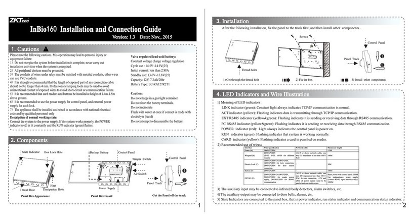
F6 Installation Guide
1. Equipment Installation
NC1 NC1
NC1
NC1
NO1 NO1
NO1
NO1
COM1 COM1
COM1
COM1
NO2 NO2
NO2
NO2
COM2 COM2
COM2
COM2
fix the device to the back plate.
Wiri ng Hole
Instr uctio n for the M ounti ng Pape r
Befor e the dev ice is fa stene d, plea se
stick t he pape r to the pl ace whe re you
want to i nstal l it, the n make ho les and
lay cab les acc ordin g to the mo untin g
paper.
F6 Mo untin g Paper
(on ly for yo ur refe rence )
Fixi ng Hole
Fixi ng Hole
10
11
the mounting paper.
is connected with ‘NC’ and ‘COM’ terminals.
Notes:
diode (equipped in the package) to prevent the self-inductance EMF affecting the system, do not
reverse the polarities.
and the device shares Ilock 1A
the device is more than 10 meters.
is equal or less than10 meters.
Access Control Panel
Side View Back View
Tamper Magnet
Reset Button
485+
485-
485+ 485-
9. Cautions
6. Wiegand Output
The device supports standard Wiegand 26 / Wiegand 34 output, so you can connect it with most of
(Please use Wiegand signal extender in long distance or interference environment).
(2) To keep the stability of Wiegand signal, connect the device and the Access Control or Card Reader in
(1) Please keep the distance between the device and Access Control or Card Reader less than 90 meters
7.Other Functions
(1) Manual Reset:
other restart it.abnormality, you can use ‘Reset’ function to
button hole with than 2mm).a sharp tool (the tip diameter is less
Operation: Remove the black rubber cap,then stick the Reset
If the device does not work properly because of misoperation or
!
Warning: No operating with power on!
same ‘GND’ in any case.
485+
485-
GND
WD0
WD1
DATA0
GND
DATA1
8. Communication
This device could use RS485 mode to communicate and exchange information with PC software
Please use specified RS485 wire, RS485 active converter, and adopt bus-type wiring.
About the terminals definition, please refer to the following table:
and supports remote control.
RS485 Bus 485+ 485- 485+ 485-
RS485
Converter
the access control devices by now.
(2) We recommend that use the DC 3A/12V power supply. For details, please contact our technical
"
(5) Please connect the GND before all the other wiring especially under the serious
"electrostatic environment,
(3) Please read the terminals description and wiring by rule strictly. Any damage caused by carefully
(4) Keep the exposed part of wire is less than 5mm to avoid unexpected connection, and result in machinery
(1) Power cable is connected after all the o ther wiring. If the device is abnormally, please shutoperated
do wn the power firstly, then make some hot-necessary checking. Kindly remain that any
improper operations will be out of the range of our guarantee.
to prevent the overlarge instantaneous electrostatic to damage device.
(6) If the power supply is a little long, please do not use the Internet
cable or other types of cable instead. When choosing the power supply cable, you should
consider that the transmission distance may cause voltage attenuation.
distance between and device
plugging may damag e device, and it is not included in the warranty.
damage.
(7) Please use specified RS485 wire, RS485 active converter, and adopt bus-type wiring. If the communication
485+
Terminals PC Serial Ports
RS485+
485- RS485-
wire is longer than 100 meters, it is needed to parallel a terminal resistance on the last device of Rs485 bus,
and the value is about 120 ohm.
personnel or sales.
(2) Tamper Switch (Backdoor Function):
be cleared.
Operation: Press the tamper switch three times after the alarm being
You can use the tamper switch to restore device number, system
password, clear administrator privileges. The user data will not
triggered 30 seconds,but not more than 60 seconds.
(1) As Reader:
EXT
RS485
PC
RS485
STATE
PWR
READER2READER1
SWITCH
OUT
ACT
PC
Access Control Panel
Connected with Reader(with External 485),
the maximum can connecting 8 readers.
#1 Reader #2 Readers #8 Readers
+12V
485-
GND
485+

Other ZKTeco IP Access Controllers manuals

ZKTeco BioPro SA30 User manual

ZKTeco

ZKTeco BioPro SA30 User manual

ZKTeco ProFace X Series User manual

ZKTeco

ZKTeco ProFace X Series User manual

ZKTeco MA500 Troubleshooting guide

ZKTeco

ZKTeco MA500 Troubleshooting guide

ZKTeco SF1005-V+ User manual

ZKTeco

ZKTeco SF1005-V+ User manual

ZKTeco Ultima Series User manual

ZKTeco

ZKTeco Ultima Series User manual

ZKTeco SpeedFace-VSL Series User manual

ZKTeco

ZKTeco SpeedFace-VSL Series User manual

ZKTeco Green Label ProFace X User manual

ZKTeco

ZKTeco Green Label ProFace X User manual

ZKTeco MultiBio 700 User manual

ZKTeco

ZKTeco MultiBio 700 User manual

ZKTeco F18 User manual

ZKTeco

ZKTeco F18 User manual

ZKTeco SpeedFace-V3L User manual

ZKTeco

ZKTeco SpeedFace-V3L User manual

ZKTeco Ultima Series User manual

ZKTeco

ZKTeco Ultima Series User manual

ZKTeco F18 User manual

ZKTeco

ZKTeco F18 User manual

ZKTeco MB20-VL User manual

ZKTeco

ZKTeco MB20-VL User manual

ZKTeco TF1600 ZKTeco User manual

ZKTeco

ZKTeco TF1600 ZKTeco User manual

ZKTeco Green Label ProCapture-T User manual

ZKTeco

ZKTeco Green Label ProCapture-T User manual

ZKTeco FR1200 Datasheet

ZKTeco

ZKTeco FR1200 Datasheet

ZKTeco G4 User manual

ZKTeco

ZKTeco G4 User manual

ZKTeco FR1200 User manual

ZKTeco

ZKTeco FR1200 User manual

ZKTeco MiniAC Plus User manual

ZKTeco

ZKTeco MiniAC Plus User manual

ZKTeco KF1000-U User manual

ZKTeco

ZKTeco KF1000-U User manual

ZKTeco ProMA Series User manual

ZKTeco

ZKTeco ProMA Series User manual

ZKTeco X8-BT User manual

ZKTeco

ZKTeco X8-BT User manual

ZKTeco ZKX5030A User manual

ZKTeco

ZKTeco ZKX5030A User manual

ZKTeco X6 Instruction sheet

ZKTeco

ZKTeco X6 Instruction sheet

Popular IP Access Controllers manuals by other brands

Hundure ECU-100 quick start guide

Hundure

Hundure ECU-100 quick start guide

Nice EPad manual

Nice

Nice EPad manual

Alvarion BreezeACCESS EZ AU-EZ System manual

Alvarion

Alvarion BreezeACCESS EZ AU-EZ System manual

Spiderdoor S14c installation guide

Spiderdoor

Spiderdoor S14c installation guide

Nortech NanoQuest Lite installation guide

Nortech

Nortech NanoQuest Lite installation guide

Progeny Chameleon manual

Progeny

Progeny Chameleon manual

Genie FR01W user manual

Genie

Genie FR01W user manual

JWS DWPS102U quick start guide

JWS

JWS DWPS102U quick start guide

Control iD iDUHF quick guide

Control iD

Control iD iDUHF quick guide

fadini ZERO.SAPE manual

fadini

fadini ZERO.SAPE manual

SDC E4KP ENTRYCHECK operating instructions

SDC

SDC E4KP ENTRYCHECK operating instructions

Sygonix 2299888 operating instructions

Sygonix

Sygonix 2299888 operating instructions

Savi SaviTag 600 Series installation guide

Savi

Savi SaviTag 600 Series installation guide

David-Link DL-AP KIT installation guide

David-Link

David-Link DL-AP KIT installation guide

Soyal AR-837-EA-T manual

Soyal

Soyal AR-837-EA-T manual

Teknim TWM-1885 Installation & user manual

Teknim

Teknim TWM-1885 Installation & user manual

Dahua DHI-ASI7213Y-V3-T1P user manual

Dahua

Dahua DHI-ASI7213Y-V3-T1P user manual

Akuvox A092 Series Administrator's guide

Akuvox

Akuvox A092 Series Administrator's guide

manuals.online logo
manuals.online logoBrands
  • About & Mission
  • Contact us
  • Privacy Policy
  • Terms and Conditions

Copyright 2025 Manuals.Online. All Rights Reserved.