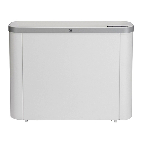
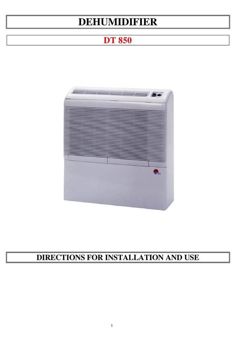
Zodiac DT 850 User manual

Installation instructions and use
DT 850
Air dehumidifier for indoor swimming pools
Réf. : N.D.009.A.EN – Ver. 05-2010

1
1. Installation...............................................................................................................2
1.1 General............................................................................................................................. 2
1.1.1 Precautions ................................................................................................................................2
1.1.2 General terms of delivery...........................................................................................................2
1.1.3 Storage and transport conditions ...............................................................................................2
1.1.4 Field of application .....................................................................................................................3
1.1.5 Operating principle.....................................................................................................................3
1.2 Description........................................................................................................................ 3
1.2.1 Technical specifications .............................................................................................................3
1.2.2 Operating conditions ..................................................................................................................3
1.3 Installation ........................................................................................................................ 4
1.3.1 Electrical regulations for swimming pools..................................................................................4
1.3.2 Installation requirements............................................................................................................5
1.3.3 Connection to surrounding air....................................................................................................5
1.3.4 Connection of the condensation drain .......................................................................................6
1.3.5 Electrical connections ................................................................................................................6
1.4 Operation.......................................................................................................................... 7
1.4.1 Control unit.................................................................................................................................7
1.4.2 Starting the appliance ................................................................................................................7
1.4.3 Checks .......................................................................................................................................7
2. Maintenance ............................................................................................................7
2.1 Maintenance instructions.................................................................................................. 7
2.1.1 Monthly checks ..........................................................................................................................7
2.1.2 Annual checks............................................................................................................................8
2.2 Spare parts ....................................................................................................................... 8
2.3 Recycling the product ....................................................................................................... 8
2.4 EC compliance certificate ................................................................................................. 8
See the appendices at the end of the manual:
- Electrical diagram
- Dimensions

2
1. Installation
1.1 General
Read this manual carefully before installing, maintaining or repairing this appliance!
The symbol indicates important information that must be taken into account in order to
avoid the risk of injury and/or damage to the appliance.
The symbol indicates useful information.
1.1.1 Precautions
1.1.2 General terms of delivery
Any equipment, even CARRIAGE and PACKING FREE, travels at the addressee's risk. Addressees
must indicate any reserves in writing on the carrier's delivery bill in the case of damage caused during
transport (confirmation to be sent to the carrier within 48 hours by registered mail and
Acknowledgement of Receipt).
Contents:
+
1.1.3 Storage and transport conditions
The appliance must be transported upright on its pallet.
The appliance must be transported upright on its pallet, in its original packaging.
If the appliance has been overturned make written reserves in writing to the transporter.
Removing or shunting any of the safety or remote control parts will automatically
void the guarantee; the same will apply for the replacement of parts by non-original
parts.
Do not discharge R407C fluid into the atmosphere: R407C is a fluorinated
greenhouse effect gas, covered by the Kyoto Protocol, with a Global Warming
Potential (GWP) = 1653 - (Directive EC 842/2006).
Do not insert any objects into the openings.
Never place any conductive parts in contact with water
Before working on the appliance, ensure that it is disconnected from the power
supply.
This device must be installed and serviced by certified professionals approved in
the electrical, hydraulic and cooling domains.
EN

3
1.1.4 Field of application
1.1.5 Operating principle
1.2 Description
1.2.1 Technical specifications
Appliance
Dehumidifying
capacity*
Power
consumed*
Power restored on
the ambient air*
Air flow-
rate
L/h W W m³/h
DT 850 1.88 L/h 850 W 2100 W 500 m3/h
* under the following nominal conditions: air 30°C - humidity 70%.
L/day Hygrometry (%HR)
Ambient temperature (°C) 55 60 65 70 75
35 43 45 49 54 60
32 37 39 43 49 54
30 33 36 40 45 50
29 31 34 38 43 48
28 29 33 37 41 46
27 27 31 35 40 44
26 25 29 33 38 42
25 23 27 32 36 40
24 21 26 30 34 38
20 16 18 24 27 30
15 10 14 15 19 22
unit protection class: IP 44
class: I
refrigerant gas: R407C
refrigerant charge: see product information plate
1.2.2 Operating conditions
operating range: 7 °C to 35 °C (temperature in the swimming pool hall)
optimum operating conditions: between 25 °C and 30 °C
Exclusive use: dehumidifying swimming pool halls.
Not to be used for any other purpose.
It must be installed indoors, in the swimming pool premises, in a location that is not
subject to freezing and no pool maintenance products should be stored nearby.
condensation tray
Dry air
Moist air
Compressor
Fan Cooling elements
condensation outlet
Air filter

4
1.3 Installation
1.3.1 Electrical regulations for swimming pools
Refer to the current regulations in force in your country.
French standard C15.100 Section 702 - U.T.E:
In volumes 0 and 1, only protection using Very Low Voltage (article 411.1) with a nominal voltage not
exceeding 12 V AC or 30V DC is allowed. The protection must be installed outside volumes 0, 1 and 2
(the appliance has a protection index of at least IP X5).
In volume 2 (see figures 702A and 702B), the appliances must be:
- either class II for lighting,
- or class I protected by a 30 mA or less ground fault circuit breaker,
- or powered by a separation transformer in compliance to paragraph 413.5.1
The appliance has a protection index of at least IP X2.
h: unknown variable
V: volume
Figure 702 B: dimensions of volumes for
above-ground pools
Figure 702 A: volume sizes for in-ground
pools and foot baths
EN

5
1.3.2 Installation requirements
1.3.3 Connection to surrounding air
1.3.3.1 Appliance on the ground (or on a support)
Do not place the device right up against a wall (risk of vibration).
1) Install the appliance on a level base, to avoid any overflows from the condensation
tray,
2) Easy access to the appliance for maintenance and connections,
3) Place nothing in front of or on the blowing and suction grates,
4) For a swimming pool building with a high ceiling or visible roof frame:
- destratification of the upper layers of the room = one or several fans with PVC blades or
an air extractor with fresh air intake.
Warning! 230 V AC appliances = must be outside volume 1 (see §1.3.1),
5) Building requirements: swimming pool building = very damp room
During building make sure that:
- the materials used are compatible with a swimming pool environment,
- the walls are sufficiently waterproofed and insulated to avoid condensation forming in the
room when relative humidity reaches 60 to 70%.
Light structure buildings (verandas, shelters...): there is no risk of deterioration of the
structure, even in case of dew as they are designed to support this (even with a relative
humidity of 70%)
6) Risk of stratification:
- height of the room < 4 to 5 meters: mechanical ventilator unit or extractor,
- height of the room > 7 to 8 meters: ceiling fans with large blades,
7) Ventilation, renewal of air,
- private pools: highly recommended
- public pools: compulsory
The air can be renewed by:
- a simple mechanical ventilation unit,
- a wall or roof extractor with fresh air intakes.
This ventilation ensures the hygienic renewal of air, the removal of any chloramines
present in the air, and the elimination of excessively hot air, whilst contributing to the
dehumidification of the room.
Pool
* minimum distance
DT 850
suction grid
blowing grid
fresh air intake
condensation drainage with angle pipe
air renewal system (see §1.3.2)

6
1.3.3.2 Appliance fixed to the wall
Using the two anchoring points at the back of the appliance in a “solid wall” (see emplacement and
dimensions in the appendix - fixing elements not supplied). Make sure that the 2 anti-vibration rubber
parts are fitted on the bottom corners.
1.3.4 Connection of the condensation drain
- fit a drain pipe of appropriate size and length on the original outlet pipe (Ø16 outer diam.)
- allow a sufficient slope to ensure a proper flow for the drained water,
- connect the extremity of the pipe to a water evacuation drain with U-bend,
- ensure that the pipe is not bent or angled, and that the extremity of the pipe is not immersed.
The outlet is located on the right side of the device when viewed from the front (see marker "AØ16" §
"Dimensions" in the appendix). This outlet can be moved to the left side (access via the rear panel).
1.3.5 Electrical connections
1.3.5.1 Voltage and protection
The electrical supply must be provided through a protection and circuit breaking device (not
supplied) complying with the standards and regulations in force in the country where it is installed (in
France standard NF C 15100).
use the supply cable delivered with the appliance: 2 poles + Earth 10/16 A in 3G1.5 (section
1.5mm²),
Extension cords and adapters must NOT be used. An adequately protected electrical socket
must be installed close to the device by a qualified technician,
Electrical protection: 30 mA ground fault circuit breaker (at the head of the line),
The appliance must be earthed.
Risk of electrical shock inside the device. Only a qualified and experienced
technician must install the device cables.
If the power cable is damaged it must be replaced by a qualified technician or by a
Zodiac Pool Care Europe service station.
Electric cables must be fixed.
Prior to any operation, check that:
- the voltage on the identification plate of the appliance corresponds to the mains
voltage available on site.
- the socket and the power supplied are adapted to the power requirements of the
dehumidifier,
- the male plug on the power cord is adapted to the socket available.
Pool
* minimum distance
** maximum distance
DT 850
suction grid
blowing grid
fresh air intake
condensation drain with angle pipe
air renewal system (see §1.3.2)
EN

7
1.3.5.3 Cable sizes
Supply cable size: for cables of a maximum length of 20 metres (calculation basis: 5A/mm²), this
must be checked and adapted depending on installation conditions.
Voltage Nominal power
consumption
Maximum powe
r
consumption Cable size
DT 850 230V-50 Hz- 4.5 A 18 A 3 x 2.5 mm² 3G2.5
1.4 Operation
1.4.1 Control unit
1.4.2 Starting the appliance
Put the appliance under power by connecting the power cord,
First run:
- turn the hygrostat dial completely clockwise (the appliance will run permanently),
- let the dehumidifier run until the desired hygrometry level is reached (typically 65%),
- turn the dial in the opposite direction until the indicator light switches off,
- the dehumidifier will now automatically maintain this level of hygrometry.
Adjusting fan speed:
- high speed: if the pool is not covered
- low speed: if the pool is covered (bubble cover, section cover, etc…)
Defrosting control and protection of the compressor: this dehumidifier features an automatic
battery defrosting system that operates by stopping the compressor and using forced ventilation.
This defrosting cycle is controlled and triggered by an Alpha 14/1 electronic module that monitors
the state of the evaporator sensor/probe (S.IN) every 20 minutes (the compressor stops for 8
minutes maximum) and the condenser sensor (S.OUT) protects the compressor. If the HP
temperature is higher than 65 °C: the appliance will stop and forced ventilation will run until the
temperature drops to under 50 °C.
1.4.3 Checks
check that the appliance is draining condensation,
2. Maintenance
2.1 Maintenance instructions
2.1.1 Monthly checks
check visually that the condensation is drained.
check for clogging in the filter:
- wash the filter with warm soapy water,
- rinse it abundantly and dry it,
- replace it if necessary.
The appliance must have filters fitted when operating.
Appliance powered off and unplugged from power supply!
A general servicing of the appliance is strongly recommended to check the proper
operation of the appliance, maintain its performance, to avoid certain faults and preserve
the building in good condition.
When making a dehumidification request, there will be a temporisation of 3 minutes before
the fan and the compressor begin to operate.
Operating indicator (light on
when the ventilation is on)
Switch for selecting fan
speed
Button for adjusting the
hygrostat (note: 0 = 100%
hygrometry)
8
2.1.2 Annual checks
check the cleanliness of the condensation drainage tube,
check that the power cord is in perfect condition
check the adjustment and operation of the hygrostat,
clean the whole unit with a slightly damp cloth,
2.2 Spare parts
Naming Item number Representation
Filter W28FIDT5
2.3 Recycling the product
Your appliance has reached the end of its working life. You would like to dispose of it or replace it.
Please do not throw it into your dustbin or into your local selective sorting containers.
When this symbol appears on a new appliance, it means that the equipment must not
be thrown away and that it will be collected selectively so that it can be reused,
recycled or recovered. Any substances it may contain which are potentially dangerous
to the environment will be eliminated or neutralised.
You can give it to a community association which will be able to repair it and put it back into circulation.
If you buy a new appliance, you can take the old one back to the reseller or ask the transporter to take it
back.
This is known as a “One-for-One” exchange.
Otherwise please take it to a waste collection centre, if your local council has set up a selective
collection system for these products.
2.4 EC compliance certificate
Z Z.P.C.E. declares that the products or ranges below:
SPECIAL POOL DEHUMIDIFIERS
DT 850
are in compliance with the provisions of the:
ELECTROMAGNETIC COMPATIBILITY directive 89/336/EEC.
LOW VOLTAGE directive 73/23/EEC, as amended by 93/068/EEC.
The following harmonised standards have been applied:
EN 60335.2.40
In the context of ongoing improvement, our products may be subject to change without notice.
Version 05/2010
Do not clean by spraying or immersing into water.
Give the appliance to a
community association. Return the used device to the reseller
when making a new purchase.
Take the used device to a
waste collection centre.
EN

1
Electrical diagram
DT 850

2
English
L-N
Power supply 230V-1N-50 Hz
Earth
M1
Fan
M2
Compressor
C1
Fan capacitor 1µF
C2
Compressor capacitor 25µF
ALFA-14/1
Defrost clock
S1
Condenser probe
S2
Evaporator probe
VO
Under voltage light
CR
Plug connector
Ml
Male plug
Fl
Female plug
I1
Fan speed selector
H
Hygrostat
THS
Compressor safety thermostat
BA
Power supply terminal block
PC
Electric plug
N
Black
B
Blue
M
Brown
G
Grey
Bl
White
R
Red
V
Purple
V/J
Green-yellow
Dimensions
Weight
Kg
DT 850 41
*

Chauffage et déshumidification de piscines – Heating and dehumidification of pools
Zodiac Pool Care Europe – Boulevard de la Romanerie – BP 90023
49180 Saint Barthélémy d’Anjou cedex – France
www.zodiac-poolcare.com
Global provider of innovative pool products and services
Produits et services innovants pour la piscine
Votre installateur – Your installer
Plaque signalétique – Product name plate
Table of contents
Other Zodiac Dehumidifier manuals

Zodiac
Zodiac Sirocco User manual

Zodiac
Zodiac DF2 User manual

Zodiac
Zodiac DF2 User manual

Zodiac
Zodiac WD002088 Guide

Zodiac
Zodiac SIROCCO 2 2M User manual

Zodiac
Zodiac SIROCCO2 Guide

Zodiac
Zodiac DT850E User manual

Zodiac
Zodiac CAE User manual

Zodiac
Zodiac SIROCCO2 User manual

Zodiac
Zodiac SIROCCO2 User manual
Popular Dehumidifier manuals by other brands

REMKO
REMKO ETF Series Operating and installation instructions

Olimpia splendid
Olimpia splendid AQUARIA SILENT Installation, use and maintenance instructions

Taurus
Taurus PLEASANT WATER PUMP Instructions for use

Kruger
Kruger KF 675BBC manual

Gardner Denver
Gardner Denver RPD Series instruction manual

Xpelair
Xpelair XPDH16T instruction manual