Zodiac SIROCCO 2 2M User manual

H0723600_REVA - 2020/11
More documents on:
www.zodiac.com
SIROCCO2
Instrucons for installaon and use - English
Dehumidier
Translaon of the original instrucons in French EN

1
WARNINGS
Carefully read the instrucons in this manual before using the unit.
GENERAL WARNINGS
• Failure to respect the warnings may cause serious damage to the pool equipment
or cause serious injury, even death.
• Only a person qualied in the technical elds concerned (electricity,
hydraulics or refrigeraon) is authorised to carry out maintenance or
repair work on the appliance. The qualied technician working on the
appliance must use/wear personal protecve equipment (such as safety
goggles and protecve gloves, etc.) in order to reduce the risk of injury
occurring when working on the appliance.
• Before handling the appliance, check that it is switched o and isolated.
• The appliance is intended to be used for pools and spas for a specic purpose; it
must not be used for any purpose other than that for which it was designed.
• This appliance is not intended for use by individuals (including children) with
impaired physical, sensorial or mental abilies, or persons lacking in knowledge
and experience, unless they receive supervision or prior instrucons on using the
appliance from a person responsible for their safety. Children must be supervised
to ensure that they do not play with the appliance.
• This appliance can be used by children under 8 and adults with impaired physical,
sensory or mental capabilies, or who lack experience and knowledge, if they are
correctly supervised or have been instructed in how to use the appliance safely and
understand the hazards involved. User cleaning and maintenance operaons must
not be carried out by children without supervision.
• The appliance must be installed according to the manufacturer’s instrucons and
in compliance with local and naonal standards. The installer is responsible for
installing the appliance and for compliance with naonal installaon regulaons.
Under no circumstances may the manufacturer be held liable in the event of failure
to comply with applicable local installaon standards.
• For any work other than the simple user maintenance described in this manual, the
product should be referred to a qualied professional.
• If the appliance suers a malfuncon, do not try to repair it yourself; instead contact
a qualied technician.
• Deacvang, eliminang or by-passing any of the safety mechanisms integrated
into the appliance shall automacally void the warranty, in addion to the use of
spare parts manufactured by unauthorised third-party manufacturers.
• Do not spray inseccide or any other chemical (inammable or non-inammable)
in the direcon of the appliance, as this may damage the body and cause a re.
• Do not touch the fan or moving parts and do not place objects or your ngers in the
vicinity of the moving parts when the appliance is in operaon. Moving parts can
cause serious injury or even death.
WARNINGS ASSOCIATED WITH ELECTRICAL APPLIANCES
• The power supply to the appliance must be protected by a dedicated 30 mA Residual
Current Device (RCD), complying with the standards and regulaons in force in the
country in which it is installed.
• Do not use any extension lead when connecng the appliance; connect the
appliance directly to a suitable power supply.
• A suitable disconnecon method, compliant with all local and naonal regulaons
on category III overvoltage, and which disconnects all poles of the power supply
circuit, must be installed on the power supply circuit to the appliance. This
disconnecon method is not provided with the appliance and must be supplied by
the professional er.
• Before carrying out any operaons, check that:
- The required input voltage indicated on the appliance informaon plate

2
corresponds to the mains voltage;
- The mains supply is compable with the appliance's electricity needs and is
correctly grounded.
• In the event of abnormal operaon or the release of odours from the appliance,
turn it o immediately, unplug it from its power supply and contact a professional.
• Before servicing or performing maintenance on the appliance, check that it is
powered o and completely disconnected from the power supply. Moreover,
check that the heang priority (where applicable) is deacvated and that any
other device or accessory connected to the appliance is also disconnected from
the power supply.
• Do not disconnect and reconnect the appliance to the power supply when in
operaon.
• Do not pull on the power cord to disconnect it from the power supply.
• If the power cord is damaged, it must be replaced by the manufacturer, an
authorised representave or a repair facility only.
• Do not perform maintenance or servicing operaons on the appliance with wet
hands or if the appliance is wet.
• Before connecng the appliance to the power supply, check that the connecon
unit or socket to which the appliance will be connected is in good condion and
shows no signs of damage or rust.
• For any component or sub-assembly containing a baery: do not recharge or
dismantle the baery, or throw it into a re. Do not expose it to high temperatures
or direct sunlight.
• In stormy weather, disconnect the appliance from the power supply to prevent it
from suering lightning damage.
• Do not immerse the appliance in water (with the excepon of cleaners) or mud.
WARNINGS CONCERNING APPLIANCES CONTAINING R410A REFRIGERANT
• Do not discharge R410A uid into the atmosphere. This is a uorinated greenhouse
gas, covered by the Kyoto Protocol, with a Global Warming Potenal (GWP) = 2088
(European regulaon EU 517/2014).
• In order to comply with the applicable standards and regulaons in terms of the
environment and installaon, in parcular Decree No. 2015-1790 and/or European
regulaon EU 517/2014, a leak test must be performed on the cooling circuit when
the appliance is rst started and at least once a year. This operaon must be carried
out by a specialist cered to test cooling appliances.
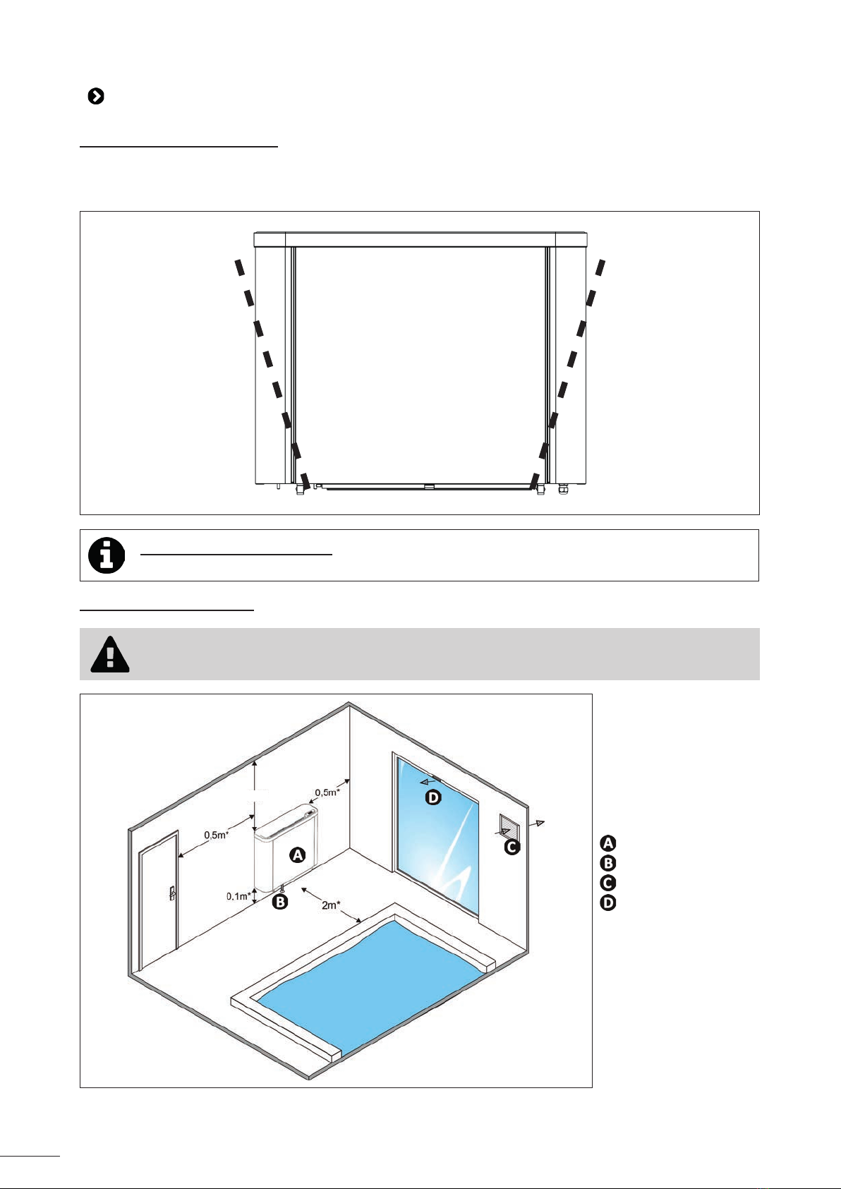
INSTALLATION AND MAINTENANCE
• The appliance may not be installed close to combusble materials, or the air duct
inlet of an adjacent building.
• With some appliances, it is essenal to t a "protecon grid"-type accessory if the
unit is installed in an area with uncontrolled access.
• During installaon, troubleshoong and maintenance, pipes may not be used as
steps: the pipe could break under the weight, spilling coolant and possibly causing
serious burns.
• When servicing the appliance, the composion and state of the heat transfer uid
must be checked, as well as the absence of any traces of coolant.
• During the appliance's annual sealing test in accordance with applicable legislaon,
the high and low pressure switches must be checked to ensure that they are
securely fastened to the cooling circuit and that they cut o the electrical circuit
when tripped.
• During maintenance work, ensure there are no traces of corrosion or oil around
the cooling components.
• Before beginning work on the cooling circuit, stop the appliance and wait for a few
minutes before ng the temperature and pressure sensors. Some elements such
as the compressor and piping may reach temperatures in excess of 100°C and high
pressures with the consequent risk of severe burns.
TROUBLESHOOTING
• All brazing must be carried out by qualied brazers.
• Replacement pipes must always be made of copper in compliance with standard
NF EN 12735-1.
EN

3
• Leak detecon; pressure test:
- never use oxygen or dry air (risk of re or explosion)
-use dry nitrogen or the mixture of nitrogen and refrigerant indicated on the
informaon plate,
-the test pressure for both the high and low pressure circuits must not exceed
42 bar (for R410A) in cases where the appliance is equipped with the oponal
pressure gauge.
• The high pressure circuit pipes are made of copper and have a diameter equal to or
greater than 1’’5/8. A cercate as indicated in §2.1 in compliance with standard
NF EN 10204 must be requested from the supplier and led in the installaon's
technical le.
• Technical data relave to the safety requirements of the various applicable direcves
are indicated on the informaon plate. All this informaon must be recorded in the
appliance's installaon manual, which must be kept in its technical le: model,
code, serial number, maximum and minimum OT, OP, year of manufacture, CE
marking, manufacturer’s address, coolant and weight, electrical parameters,
thermo-dynamic and acousc performance.
Recycling
This symbol is required by the European direcve DEEE 2012/19/EU (direcve on waste electrical and
electronic equipment) and means that your appliance must not be thrown into a normal bin. It will be
selecvely collected for the purpose of reuse, recycling or creang value. If it contains any substances that
may be harmful to the environment, these will be eliminated or neutralised. Contact your retailer for recycling
informaon.

4
Tip: to make it easier to contact your retailer
• Write down your retailer's contact details to help you nd them more easily and ll in the "product"
informaon on the back of the manual; your retailer will ask you for this informaon.
• Before handling the appliance, it is vital that you read this installaon and user manual, as well as the
"Warranes" booklet delivered with the appliance. Failure to do so may result in material damage or
serious or fatal injury and will void the warranty.
• Keep and pass on these documents for later viewing throughout the appliance's service life.
• The distribuon or modicaon of this document in any way is prohibited, without prior authorisaon
from Zodiac®.
• Zodiac® is constantly developing its products to improve their quality. The informaon contained
herein may therefore be modied without noce.
CONTENTS
❶ Specicaons 5
1.1 I Descripon 5
1.2 I Technical specicaons 6
1.3 I Dimensions and marking 7
1.4 I Operang condions 7
❷ Installaon 8
2.1 I Installaon requirements 8
2.2 I Installaon close to the pool (wall-mounted appliance) 9
2.3 I Connecon of the condensate drainage line 10
2.4 I Access to the electrical connecon terminal boards 11
2.5 I Electricity supply connecons 12
2.6 I Opon connecons 13
❸ Use 14
3.1 I User interface presentaon 14
3.2 I Operaon 15
3.3 I Appliance conguraon 16
3.4 I User funcons 20
❹ Maintenance 23
4.1 I Servicing 23
❺ Troubleshoong 25
5.1 I Appliance behaviour 25
5.2 I Lighng of LEDs on the printed circuit board 25
5.3 I Sengs 26
5.4 I Wiring diagrams 27
EN

5
❶ Specicaons
1.1 I Descripon
SIROCCO2
Wall mounng rail + screws (x5 Ø6 mm)
Filter
Base
“Hot water coil” kit
“Electric heater” kit
“Remote control” kit
“Built in” kit
: Included
: Available as an accessory

6
1.2 I Dimensions and marking
SIROCCO22M 3M 5M 5T
A1,060 mm 1,410 mm
B300 mm
C800 mm
A
C
B
C
A
C
Front Side Rear
A
B
A
B
Top Boom
User interface
Blower grid
Integrated wall mounng rail
Condensate drainage outlets
Filter + extracon grid
Levelling screw
Cooling secon
Electrical secon
EN

7
1.3 I Technical specicaons
SIROCCO2 (without opons) 2M 3M 5M 5T
Voltage 220 - 240V / 1 / 50 Hz 380 - 400V / 3
/ 50 Hz
Polluon class I
Polluon degree 2
Overvoltage category II
Nominal electric current requirement A5.5 9.8 12.1 4.7
Maximum electric current requirement A8.7 14.3 18.5 7.3
Minimum cable secon1mm² 3 x 2.5 5 x 2.5
3G2.5 5G2.5
Dehumidifying capacity2L/h 2.5 3.5 5.5 5.5
Power input2W1,210 2,150 2,660 2,720
Air ow ("Standard" mode) m³/h 600 800 1,000
Acousc power: "Standard" mode db(A) 61.5 65 63.5 64.5
Acousc power: "Silence" mode db(A) 58.5 62 60 61
Approximate weight kg 72 83 103
Refrigerant gas R410A
Refrigerant gas load kg 0.88 1.15 1.65 1.65
TeqCO21.84 2.40 3.44 3.44
Service pressure (max / min) bar 42 / 12
MPa 4.2 / 1.2
Service temperature (max / min) °C 65 / -16
Protecng rang IPX4
Opon “back up heang”
Power W2,000 3,000 4,500 4,500
Nominal electric current requirement A9.1 13.7 20.5 6.8
Opon “hot water baery”: inlet water temperature at 70 °C minimum / 90 °C maximum
Power W7,070 8,110 11,090 11,090
Water ow m³/h 0.3 0.35 0.47 0.47
Head loss kPa 27.85 38.85 34.51 34.51
Opon “hot water baery”: inlet water temperature at 40 °C minimum / 50 °C maximum
Power W2,150 3,160 3,710 3,710
Water ow m³/h 0.18 0.27 0.31 0.31
Head loss kPa 15.77 22.87 17.31 17.31
1 Values provided as a guide only for a maximum length of 20 metres, these must be veried and adjusted to suit the installaon requirements and
the installaon standards of the country.
2 Model without opons, under the following nominal condions: air 30°C, humidity 70%.
1.4 I Operang condions
Operang range1 :
• Dehumidicaon funcon: between 10°C and 40°C.
• Heang funcon: between 5°C and 40°C.
Opmal bathing condions:
• 26°C ≤ Ambient temperature in the pool room ≤ 28°C.
• 60% ≤ Ambient relave humidity ≤ 70%.
1Ambient temperature in the pool room.
• The air temperature setpoint can be adjusted to the same level as that of the water to obtain the best
bathing condions.

8
❷ Installaon
2.1 I Installaon requirements
• When the appliance is installed and protected by a residual current device (RCD) with a maximum amperage
of 30 mA, it should be installed at a distance of at least 2 metres from the edge of the pool.
• If no RCD is installed with the appliance, it should be installed at a distance of at least 3.5 metres from the
edge of the pool.
• Do not li the appliance by handling the body: use straps (not supplied, see § "1.1.1 I Posioning the
appliance").
• Make sure the appliance is level, to avoid any overow from the condensate drip tray (adjust using the two
hexagon screws, see § “2.2 I Installaon close to the pool (wall-mounted appliance)”).
• Only indoor installaon is possible: ensure there is easy access to the appliance for maintenance and
connecons.
• Allow at least 10 cenmetres above it for the lter. If this is not the case, the cost of handling the appliance
will not be covered.
• Do not put anything in front of or on top of the blower and extracon grids.
• It is mandatory to install an-vibraon studs (supplied) between the appliance and wall it is mounted on.
• The wall should support the weight (see § “1.2 I Technical specicaons”) of the appliance.
• For a pool room with a high ceiling or visible roof frame: destracaon of the upper layers of the room =
one or several fans with PVC blades or an air extractor with fresh air intake. Cauon! 230 V AC appliances
= must be outside volume 1 (see below),
• Risk of stracaon:
- height of the room < 4 to 5 metres: mechanical venlator unit or extractor,
- height of the room > 5 to 8 metres: ceiling fans with large blades.
• Building requirement: pool room = high relave humidity. Check during construcon that:
- the materials used are compable with a swimming pool environment,
- the walls are suciently waterproofed and insulated to prevent condensaon from forming in the room
when relave humidity reaches 60 to 70%,
Buildings with lightweight structures (verandas, shelters, etc.): there is no risk of deterioraon of the
structure, even in case of dew as they are designed to support this (even with a relave humidity of 70%),
• Venlaon, renewal of air:
- private pools: highly recommended,
- public pools: compulsory.
The air can be renewed by:
- a simple mechanical venlaon unit,
-a wall or roof extractor with fresh air intake grids.
This venlaon ensures the hygienic renewal of air, the removal of any chloramines present in the air, and
the eliminaon of excessively hot air, whilst contribung to the dehumidicaon of the room.
• The appliance must be installed in accordance with the IEC/HD 60364-7-702 standard and the naonal
regulaons in force for swimming pools.
Tips to reduce noise polluon emied by your dehumidier
• Install it in an open space (sound waves are reected on surfaces).
• Acvate the "Silence" mode (see § "3.3.4 Acvang/deacvang "Silence" mode"), the dehumidier
will operate at a lower noise level with a slightly lower dehumidifying capacity.
EN

9
2.2 I Installaon close to the pool (wall-mounted appliance)
2.2.1 Posioning the appliance
• At least two people are required for moving the appliance.
• Use straps (not supplied) when liing the appliance so as not to damage it when posioning it.
• Place the straps in the posions shown by the doed lines in the following diagram:
Informaon: weight of appliance
• The le side of the appliance (as seen from the front) is heavier than the right side.
2.2.2 Selecng the locaon
• The appliance must be mounted on a wall to avoid any risk of lng, even when it is ed
with a base.
1m *
: SIROCCO2
: Condensates drain
: Air renewal system
: Fresh air intake
* minimum distance

10
• To mount the appliance on a (solid) wall, follow these steps:
❶
560*
150 x4
500 min500 min
SOL
560*
225 x4
500 min500 min
SOL
2M and 3M models 5M and 5T models
*Distance to be respected when the dehumidier is mounted on the base. If this is not the case, this distance can be increased.
❷ ❸
x5
❹
2.3 I Connecon of the condensate drainage line
• The angle should be sucient to ensure a correct ow.
• Drainage takes place through the intermediary of a syphon or funnel.
• Outlets underneath the appliance.
• Ensure the syphon is lled with water so as to avoid air entering the condensate drainage pipe.
Condensate drainage outlets (view of appliance from below)
Tip: condensate drainage
Cauon, several litres of water can be drained from your appliance each day.
We strongly recommend connecng the drain to a suitable water drainage system.
EN

11
2.4 I Access to the electrical connecon terminal boards
❶ ❷
❸ ❹
❺ ❻

12
2.5 I Electricity supply connecons
• Before any work inside the appliance, you must cut the appliance’s electricity supply as there is a risk of
electric shock which may cause material damage, serious injury or even death.
• Incorrectly ghtened terminals may cause the terminal box to heat up, which can invalidate the warranty.
• Only a qualied and experienced technician is authorised to carry out cabling work within the appliance or
to replace the power cord.
• The installer must consult the electricity provider if necessary and ensure that the equipment is connected
correctly to an electricity network with impedance under 0.095 ohm.
• The dehumidier's electrical supply must be provided through a protecon and circuit breaking device (not supplied)
complying with the standards and regulaons in force in the country in which it is installed.
• The appliance is provided for connecon to a general power supply with a TT or TN-S neutral regime.
• Electrical protecon: by circuit breaker (D curve, rang to be dened according to the table in §”1.3 I Technical
specicaons”), with a suitable dedicated residual-current device (circuit breaker or switch).
• Addional protecon may be required during installaon to guarantee the overvoltage category II.
• The power supply must correspond to the voltage indicated on the appliance's informaon plate.
• The power cord must be insulated against any cung or hot elements that may damage or crush it.
• The appliance must be connected to an earth socket.
• The electrical connecon lines must be xed.
• Use the gland to pass the power cord into the appliance.
• Use the power cord (RO2V type) adapted for outdoor or buried use (or run the cable into a protecon duct) with an
external diameter of between 9 and 18 mm.
• We recommend burying the cable at a depth of 50 cm (85 cm under a road or path) in an electrical duct (red ribbed).
• If this buried cable meets another cable or pipe (gas, water, etc.), there must be more than 20 cm between them.
• Connect the power cord to the spring connector terminal board inside the appliance, as shown below:
❶ ❷
9 - 10 mm
Pull the lever up as far as it will go, then connect the
cable. Return the lever back to its inial posion.
EN

13
2.5.1 Connecng the pool shuer switch
• Connect the pool shuer contact cables to terminals X9.5 and X9.6 as shown below.
2.6 I Opon connecons
Opon mounng and acvaon :
• Refer to the installaon and use manual supplied with the opon.
2.6.1 "Hot water coil" opon
• This opon allows the dehumidier to be used to heat the air in the room in which it is installed. A primary hot
reservoir (exchanger, boiler, geothermal heat...) has to be mounted upstream. To do so, use the “hot water coil” kit
available as an accessory.
• For the connecon, consult the manual supplied with the kit.
2.6.2 "Electric heater" opon
• This opon allows the dehumidier to be used to heat the air in the room in which it is installed. To do so, use the
"Electric heater" kit available as an accessory.
• For the connecon, consult the manual supplied with the kit.
2.6.3 "Remote control" opon
• This opon enables the appliance's user interface to be transferred in order to control the appliance remotely. To do
so, use the “remote control” kit available as an accessory.
• For the connecon, consult the manual supplied with the kit.

14
❸ Use
Your dehumidier operates based on a heat pump with extracon of the warm, humid air in the pool room and delivery
of dryer, hoer air.
It is ideal for maintaining a humidity level that is between 60% and 70%.
When the humidity level is lower than 60%, this leads to a feeling of excessive cold when leaving the water.
When it is higher than 70%, this leads to too much moisture and condensaon in the room.
3.1 I User interface presentaon
3.1.1 Presentaon of the display screen and funcon keys
Descripon
Mul-funcon display
“On/o” or “back” key
"Up" or (de)acvaon key for the heang funcon
"Down" or (de)acvaon key for the "Silence" mode
SET
“Adjustment” or “conrm” key
3.1.2 Descripon of the display screen
Symbol Descripon Steady Flashing O
On/O Appliance switched o /Appliance in operaon
Dehumidicaon Appliance in dehumidi-
fying mode Appliance med /
Heang Appliance in heang
mode / /
Defrosng Defrosng acve / /
Sengs Appliance in “sengs”
mode / /
Test mode Test mode acvated / /
Compressor Compressor on Compressor med Compressor idle
Fan Fan(s) on Fan med Fan(s) o
EN

15
Electric heater Electric heater heang /Electric heater o
Circulator (hot water coil
opon) Circulator on / Circulator idle
Alarm Alarm in progress / /
Celsius
Appliance congured
to measure in degrees
Celsius
/ /
“Manual” mode Programming using
“manual” mode. / /
Humidity level percentage Appliance congured as
a humidity sensor / /
3.2 I Operaon
3.2.1 Switching on the appliance
• Power on the appliance (by switching on the general terminal board),
• The program version remains visible for 5 seconds then "OFF" and "KEY" is displayed before the appliance starts.
Only on Sirocco 5T models (three phased):
• This operaon must be only be carried out by a qualied professional.
• The phase order controller protects the compressor. It is forbidden to invert phases:
-On the power contactor.
-On the compressor.
• When the dehumidier is switched on, check the status of the phase order controller as shown below:
Indicator light
status
OK~ OK~
• If there is a phase inversion or missing phase:
1. Disconnect the appliance from the power supply;
2. Invert two phases directly on the appliance connecon terminal board;
3. Restore power to the appliance and check the status of the indicator lights.

16
3.2.2 Starng the appliance
• Press and hold (longer than 3 seconds) .
• The screen displays all of the symbols along with an audible beep. The value displayed on the screen corresponds
to the relave humidity (%). The ambient temperature can also be simultaneously displayed (°C). To do this, just set
the heang mode to "Hetr" or "coiL". (see §3.3.2 "Conguring the heang mode").
3.3 I Appliance conguraon
When the dehumidier is installed, it must be congured to ensure opmal operaon best adapted to the condions of
use. This can be done via the "EASY" menu (access reserved for qualied professionals and requiring an access code).
To access and browse the menus:
• Press and hold (longer than 3 seconds)
SET
.
• Browse using the and keys.
• Press
SET
to conrm (go to a sub-menu or conrm a selecon).
• Press to go back to the previous screen.
Informaon: list of menus
Menu Descripon Restricon
USER Menu dedicated to users for managing setpoints /
EASY Menu intended for qualied professionals so that they can congure
the appliance aer the inial installaon and/or adding an opon. Reserved
for qualied
professionals and
requiring an access
code.
INIT PARA Informaon menu dedicated to the appliance's status and basic
sengs
ADVI Menu dedicated to the appliance's advanced sengs (“Read” mode)
ADVDr Menu dedicated to the appliance's advanced sengs (“Write” mode)
3.3.1 Conguring the venlaon mode
• In the “EASY” menu, browse with the or keys unl you reach the “P16” seng, then press
SET
to
conrm.
• Using the or keys, choose the desired venlaon mode:
- 0 = intermient venlaon. The venlaon comes on every 30 seconds for 5 minutes.
- 1 = permanent venlaon (default seng). The venlaon is always on.
• Press
SET
to conrm.
• Press to go back to the previous screen.
Press a number of mes to return to the home screen.
EN

17
Informaon: the importance of the venlaon mode
• Venlaon helps to ensure that air circulates correctly, meaning that the temperature and humidity levels
are more even throughout the room.
• Bathing comfort can be signicantly and economically improved by improving venlaon.
3.3.2 Conguring the heang mode
When installing a heang kit ("electric heater" or "hot water coil"), the appropriate heang mode seng must be used.
• In the “EASY” menu, browse with the or keys unl you reach the “P44” seng, then press
SET
to
validate.
• Using the or keys, choose between “dbsl”, “Hetr” or “coiL”.
- dsbL = no heang opon.
- Hetr = electric heater (default seng).
- coiL: hot water coil.
• Press
SET
to conrm.
• Press to go back to the previous screen.
Press a number of mes to return to the home screen.
Informaon: home screen update
• When the heang kit is conrmed ("electric heater" or "hot water coil") the home screen is updated with
the simultaneous display:
- The relave humidity level (%),
- The ambient temperature (°C or F°) in the pool room.
Only the heang mode is conrmed at this stage of the conguraon. The funcon will then have to be acvated or
deacvated from the home screen:
To enable the heang opon:
• Press and hold (longer than 3 seconds) the key, the screen shows “CHU ON”.
• Enabling the heang opon is visible on-screen thanks to the symbol.
• The symbol indicates that the heang is acvated but not necessarily acve. The only indicaon that
the heang funcon has started is when the or LED is lit.
To disable the heang opon:
• Press and hold (longer than 3 seconds) the key, the screen shows “CHU OFF”.

18
3.3.3 Conguring pool shuer mode
The pool shuer mode is used to adapt the dehumidier and heang funcons to the pool status (covered/not
covered).
When the shuer is detected as closed, the heang setpoint temperature switches to the (lower) point dened in
seng P66 (see § 3.4.3 "Conguring setpoint temperatures").
This seng helps to reduce energy consumpon during periods when no one is swimming.
Uncovered
Setpoint T (°C) = 28°C / P07 Covered
Setpoint T (°C) = 20°C / P66
This example shows the temperature setpoint automacally switching from “P07” = 28°C to “P66” = 20°C when the pool is covered.
To acvate this funcon you will have to:
1. First connect the pool shuer switch (see §2.5.1 "Connecng the pool shuer switch");
2. Acvate the pool shuer mode:
• In the “EASY” menu, browse with the or keys unl you reach the “P67” seng, then press
SET
to
conrm.
• Using the or keys, select:
- Yes = acvate the automac shuer mode (default seng).
- No = deacvate the automac shuer mode.
• Press
SET
to conrm.
• Press to go back to the previous screen.
Press a number of mes to return to the home screen.
Informaon: advantages of the pool shuer funcon
• When the shuer is detected as fully closed no more pool water can evaporate. The dehumidicaon
funcon is then automacally deacvated.
• If a dehumidicaon process is ongoing when the pool is covered, the funcon will only be deacvated
once the humidity setpoint has been reached.
EN

19
3.3.4 Conguring the test mode
Once the installaon of the dehumidier is nished, the installer can check the appliance in test mode. This mode is
used to force the dehumidicaon funcons (and the heang kit, if installed).
To acvate/deacvate the test mode:
• In the “EASY” menu, browse with the or keys unl you reach the “P25” seng, then press
SET
to
conrm.
• Using the or keys, select:
- 0 = stop test mode (default sengs)
- 1 = start test mode.
• Press
SET
to conrm.
• Press to go back to the previous screen.
Press a number of mes to return to the home screen.
• When the test mode is acvated, the symbol is displayed.
To set the test mode duraon:
• In the “EASY” menu, browse with the or keys unl you reach the “P26” seng, then press
SET
to
conrm.
• Using the or keys, choose the desired duraon (in minutes). The default duraon is 30 minutes. Note that
the duraon must be set before running the test mode. Changes to this seng during the test will only be taken
into account later.
• Press
SET
to conrm.
• Press to go back to the previous screen.
Press a number of mes to return to the home screen.
• If the test mode is manually stopped prematurely ("P25" = 0), the symbol remains on the screen
unl “P26” has counted down.
Several checks can be performed in test mode:
• Check that hot air is coming out of the appliance's blower grids.
• Check that the following symbols are displayed:
Dehumidicaon Heang
or
Depending on the test condions, checking the condensate drainage is not mandatory.
This manual suits for next models
3
Table of contents
Other Zodiac Dehumidifier manuals

Zodiac
Zodiac WD002088 Guide

Zodiac
Zodiac CAE User manual

Zodiac
Zodiac SIROCCO2 Guide

Zodiac
Zodiac SIROCCO 110 User manual

Zodiac
Zodiac DF2 User manual

Zodiac
Zodiac Sirocco User manual

Zodiac
Zodiac DT 850 User manual

Zodiac
Zodiac DF2 User manual

Zodiac
Zodiac DT 850 User manual

Zodiac
Zodiac SIROCCO2 User manual