5
4.2 Drainage
There are four outlets for the drainage tube. In order to change the outlet, the rear panel shall be dismounted.
When remounting the rear panel, care should be taken to return all screws and washers to their original location.
Connecting the permanent outlet Ø13.
-Connect the pipe to an outlet tube with the correct diameter.
-Push the other end of the tube into a drain, making sure that the tubing cannot be twisted or folded.
-The entire length of the tube must be slightly inclined.
-Ensure that the outlet of the drainage pipe is not under the water level in the drain.
Notice :
-In very cold weather conditions precautions shall be taken to prevent drainage pipe from freezing.
-Drainage pipe shall not be in contact with the compressor.
5. OPERATION
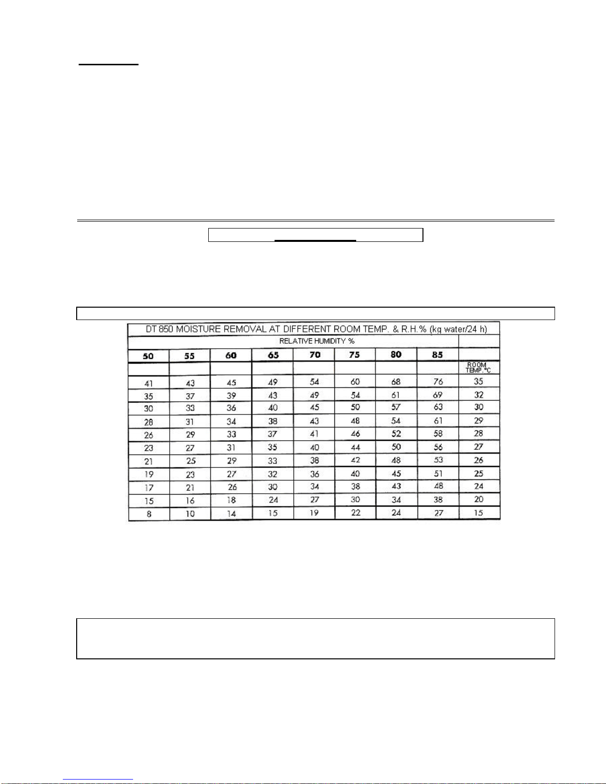
* Technical data:
•Mains 230V –50 Hz.
•Air flow rate 500 m3 / h.
•Refrigerating agent R407C (710g).
•Power consumption 850 W*.
•Heat recovery 2100 W*.
•Current 4,5 A (start 18 A).
•Net weight 45 kg.
* at 30°C and 70% R.H..
Important: DT 850 should not be used in temperatures below 7°C and above 35°C
Automatic humidity control
This dehumidifier is equipped with an adjustable humidistat control (fig.4 -n°3-). When first starting, turn the humidistat
control clockwise full tilt.
At this setting the dehumidifier will run continuously, regardless of the humidity level. Allow the unit to run in this way until a
comfortable level of humidity is reached. At this point, slowly turn the humidistat control anti-clockwise until the unit switches
off. The dehumidifier will now automatically maintain the humidity at this level.
The other switch controls the ventilator speed (fig.4 –n°2-).
Important information:
Every time the dehumidifier is on demand, the compressor and the ventilator start after 3 minutes.
The light POWER in on when the ventilator runs.
Defrost control
This dehumidifier is equipped with an automatic de-icing mode to defrost the refrigeration coil during low temperature
operation.The compressor is switched off whilst the ventilator keeps running. This cycle of de-icing is controlled by an
electronic module Alfa 14/1 that checks the sensor of the EVAPORATOR (S.IN) every 20 minutes (compressor is stopped for
maximum 8 minutes if temperature of the coil is below –1°C) and the sensor CONDENSER that stops the compressor if the
temperature of the condenser is over 65°C.