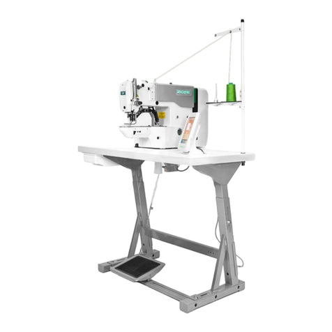
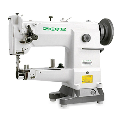
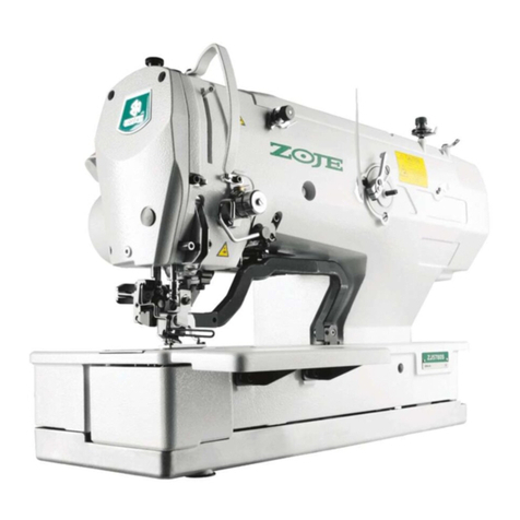
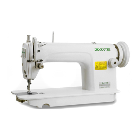
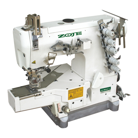
ZOJE ZJ20U93 User manual

AUTO-OIL FILLED ZIGZAG SEWING MACHINE
flmmeJJ~
OPERATION MANUAL
'11**¥*
PARTS
BOOK
en
Ill·
ClJJilUil!fl
m
ft2
fR
fai
BIJ~
at
ZOJE
SEWING
MACHINE
CO
.. L
TO
.

-,
J@iZf!
•••••••••••••••••••..•••••••••••••••
·····•·•···········•····•·····························•••••·••······ 1
_,
~~ti
ff
iilj)i
...
.
...............................
.
.......
.
..............................................
. 1
_,
ti
11:
M
aq
Jt
~
.-Ijij'
....
.
.......................
..
...............................................
.
.....
.1
f
Jl
H
a-g
ilil
ii
..
.
....
...
..............................
.
.........
.
..........................................
.. l
tt~~~m
..................................................
.
...
..
......................................
. 2
"f::;.,if11.tt~3t-·································································································
2.
-t,
h1t,ff
...............................................................
..
....................................
2
)"',
~~'t't:tt
.........................
.
............................
.
.........
.
.....................................
2
ft,
~,t,~~-·········
· · ·
············································
··
····································
3
+'
JJ[ij~
........................
....
.......................
,
....
.
............................................
3
+-,
t;l~-t1E:Jla9i}!J~
.
..
............................................
...
..
..
........
.
...................
.
....
4
+=
...
ffiJJtllffijJ
ag~~·························
·
·····························································
4
+
.=,
oo~~~::tJa9~;;-
.................................
.
.................................................
4
+IZll,~t~•~*JJ&fr~tt:JiP-l~
........................................................................ s
+
.n."
1i£
ti~
jJ
iJi]-;;-
..••.............•........•...........•.........•.....................•......••........ 5
+~
...
ttm.~~~·····--·················································
-
·
······································
s
+-t"
-tt
!e(J!P
iltt
~.§[
)~ill];;...............
.... ..
................................................
6
+
)"',
*'1~-ftlJ.*jfB:M:~~':;l'
···································
·
····
··
·····································
6
+n
,
a-m:aag~~··················
·
·····
·
·····················
·
···
·
·····
·
·······
·
·······················
6
=+'
-~$1*~~~·····································
·
········································
··
····
7
=+-,
Jl..f!i~~:n;t~llffi!ftt:J~Jll
................................................................. 7
=+
=,
tllfftt:J~jp
.......................................................................................... 9
-+-
--
.=.,
±.~tl*~~
............................................
..
.....................................
9
- I -

CONTENTS
1.
Applic
.
ation
....•.......•.••.••••••••
.••
•••••••••.••..•.••.•.•••.••.•.••••.....•.....•.•.•••.•......••.•••••••.
2.
Secure
operat
io
n...................................................
.
................................
.
....
1
J.
Caut
ion
be
foe
op
eration..........................................................
.
....................
t
4. Lubrication
••
.•
••.•....•••......•••..•••.••......••••..••.•.••••...•..••...................••.......••.••.•• 1
5.
Se
lection
of
needle
and
t.hread................................................................... 2
6.
I
nserting
of
needl.....................................................................
...
...............
2
7.
Replacing
bobbin
•.••..•••.......•._........•••....•......•..••.....•..••••.•.••.
••.•••
•.•...•••.••.••••.• 2
8.
Tbread
the bobbin case.......................•...................••...............•..........
•.
.•..•• 2
9.
The
installation
of
the bobbin..................................................................... 3
I0.
Thread
surface stitches.............................................................................. 3
11
.
Adjusting
stitch
lengtb
•..•.•••.....•••....••..••••....
60
•••••••
•••
••••••••••••••••••••••••••••••••
• 4
12.
Adjusting
presser
foot
pres
s
ur
e...
....
.
....
..
..............................
.
.............
.
......
4
13. Adjusting needle
thread
tension................................................................ 4
14. Regulate the length
and
tendion
of
take
-
up
spring.............
..
............... 5
15.
Adjust
bobbin
thread
tendion
••••••••••••.•....••.•.•......••.•.•...•.•••••••..•..•.••••••••... 5
16.
Adju
.
st
needle p
os1t1on
............................................................................... S
17.
The
ad
justment
of
horizontal
di
sta
nce
................
...
..
.................................
6
18.
To
mount thread
uo1'
inder
•••••••...••••••....•...........•...•.•••.........••••.•••••••.•.•...•• 6
19.
Assemblage
of
belt
cove
r....•....•...••..••......••.....•••••.•.••••..•••••••••••.....•.•.•••.••.• 6
20.
Munt
knee lifter....................................................................................... 7
2
l.
Modes
of
seve
ral
sewing stitch
and
application
of
accessory................... 7
22.
Maintain
of
ma
chine
...••••••.••••••••.••••••...•••••.••..•••.....••.••..•..••.•...•••.••.••••.•
••
•. 9
23.
I\
1
ain
sp
eci
fication
.....•••••..•••.•.•.••••.•...•••..•.•.•.......•.....•..•...•..••
•.
.•..•......•.••... 9
-
ll
-

-,
I'll~
I
APPU:CATIO~
iJE~L
i
~Rlfl!Q~~-
il<J:
JIJ
~.
¥.li11l.
't
rti.
~!!~
fl'lM.
~
-
~~~~~
-
~~-§~aR~
.
!l<m
7iilim
11t
tfJ
mHiv
~fll'fl
f<l
fl'lJJOi!rllll
ili\141
~
~ T
~41<~fl'~tlfl'l~~~!l!
.
This
series of
rigzag
sewing machine is used to
zigzag, embroidery
and
lockstitch
on
thin. n•
wdiun
and
thick material
for
garmen
t, bed articles. shoes.
towels and wall carpet.
Extra accurate mechanical transmission and
knee-
control
.wing
range
unit
assure
many
kinds
or
perlect
embroidery stitch.
=,
:Et :i:
lii
'F
S~
2. SECURE
OPERi\TIO~
1.Jift!A
m1li~;&
~lftiJIHHflSlfRJ
\J~
1'!
ffliitl9l'l!fti.
/Jlif
{Vft;
2.fl!l!HMllP.t,
'l<~~~,e.i>ji~l!1~~;
3.~!H'1~
lil
til$f!I'
(
~u
:
tJ
Ltt.
JJi
,
!lll,
#Iii.
ilil'f!f
fol!!<>~
).
jffl,
i:IHG:l:Xllft:.A.~1UUl
.(!If,
£•il
*f~
'1!.
11'it*
*
ii!Ztl<
r
iti.
tit
liti!J..
:
4
.
Vt~!i'J!ltJ.
~
l'l
~:C:fti~ilfh'Vjl:tt;t:AJAilt
ti
;
L) The operator should be rtained.
and
u.,..deI$18lld
this manual \'ery well before operating.
2)
All security equipemnts
should
be
ILxed
very
'\\'ell while
running
the machine.
3)
Tu
rn orr
Lhe
DOWer
or
dr
aw
t
he
l)Ower off.
while unfi:dg soc
aooe6SOr'.es
(like
.-Ile.
prtSSet
fooL
needle Dlate, feed
dog
a
nd
bobbin
sase). win
ding
thread
and
no
operator
is
at
the workplace maintalning
the machine.
4)
Maintenance
and
adjustment of the machine
should
be
carried
by
Dto
iessional teehnician
5)
The
electricity equipment should
be
managed
by
managed
by
wireman
or
prolessional technician•
.=.'
tli'FlllJ!'.19it~
-~
3.
CAUTION
BEFOE
OP
ERA
TIO:\
.l9i!St111.8
!II~.
,Q:.jjj
iVl
Jlit~l'
Jll
$ Jl;
1.
It
IX~/ll~
~
".
&
Mi
M
l
il<
ill~.
:J'c
jTJJ1
1
)!J:
L~E~~~ffi/t~~$.
~~W~~N~~:
i.
J:.~-li!.
~
lifll~;li(ll]
iiH
l
.
To
avoid
the
damage of
madline.
don care
of
the
followinJI:
.,.
I)
Please clean
the
machine thoroughly,
add
enough
oil before first
usa11e.
2)
Check the normal
cy
of voltage connecting oil
before first usage.
3) The upper wheel should rotate in the d.irec'Jon
facing
the
operator.
11!1.
tll
R
tt.J
iii!
if
(Ill I ' 2 )
~
.
L
U
BRI C A
TION(
flg.l,l
)
l.
l!!
;lfVl.:'h.
ll-Jil!i.£ti1:.A!tWlllil!lx
HIGH
iCft~
(111
l).
2.~il!llliflf':f
ADD
OIL
iC~8'1.
~lli.llliillll(l'!l
I).
3.lXJ~.fi.
3hlJ
Vl.l!J
,
$
'1fi!i
lllllilllit~
~
l!
U~llll11!
A.
ill.
IJll
ifil!It
iE
11W
E 3).
4.
11T
JII
ff<Jilit
li
38c
8't.
fU
l'.
Jl;
20.0mm/s.
:r£
1s'C
U.t.
tt<I
Jl'.)9
0.888g/m,
13!\il~
lll
18
"}ll\J.
l).Tum Over the machine head.
Pout
lhe oil into
the oil pan
cu
the
"HIGH" marks.
2).
\\hiJe
the
oil is
bowr
than
•ADD
OIL._
please
poru the
new
oil
int
o the oil pan.
3).Tun on the m&hine at.er pouting
oiJJf
the
oil
SPlaCh
on
the
oil w1ndow
A.
freauemly, the lubrication
is goodorder.
4)
.The
>iscosity
the
used oil of should be 20.
oomm/ s when the oil temperature is 38'C.
The
denSily
of
the
used
oil should
be
0.888g/m
when the o
il
tempera
ture
is
15
'C.
We suggest
that
you
should use No.18 white oil.
HIGE
l
~
Figl
l'f!Fig.2

Ji,
tt~((.J~ill
S.
SE
LEC
TI
ON
OF
~EEDLE
AN
D
THREAD
Mll!
::r-lll!SU4.
ailt
111mefr141'fJin.
tt·&
Ill~.
!ft!
~~IRl:t<
!:
~
l
ii.Ill~!!!!
flt+
'l'~tt
)q:
*l
~Ulltti&
120
60
30
111.tt.k'T
#!2
-
#16
#!8
-#19
(!/
!OOmm
) #10
(80-100
) (110
-12
0)
ill.ti
~!,If
l910-05(135x9)
nJ
Jfl
:lt
it~
!!'!.Ill~
tiJ
Utt
Select
the
apropriate
thread
and
needle
according
to
the
different sewing material
as
following:
Applicable
kind Thin
~IB!ium
hea•-y
Hea>-y
of w:erial
rntttrial
material
Max
si2e
of
l20
60
30
thread
Needle size
#!2
-
#16
118-1119
(1/IOOmm
) #10
(80-100)
(1
10-1
20)
!\eedle
M>e
l9I0-05(135)(<))
Other equal suitable si2e thread usable.
,\
,
t'ltt((.J:it~(~
3)
6.
T
NS
ERT1
:-JG
OF
N
EEDL
(F
ig.
3)
'I
/~
00
Fig.3
at~J:~tfttff
J:'1-fUU~lt
ri
.
~:Tf~tt~!Al
!UT I,
f.l.t1LttWilii'1Jlili,
*l§iiil
0
J~fl!.fl,
t~Fa.
1'i'
~:llt61tltr
!,
Turning
the
hand wheel and raise
the
needle
bar
to the highest position. then loose the needle
rightening
screw
I. Insert
the
needle
in
the
oe«lle
bar
and push
il
up
as
far as
it
will
go.
-2-
Make sure its
Jon
g groove faces toward the
front.
Tighten
needle
set
screw
I securely.
-t;, d1
1'..,lf(lll
4, Ill
S)
7.REPLACl:-lG
BOBBIN
C
ASE
(Fig.4,
S)
'
Ill
Fig.4
3 •
i:BFig.5
tfl
fiH!!
n
it
I.
1!jl
UJ
!flIii
~
.C';t
2.
~J:~·t>l5D<t,
~*9Gtt:tftf<f1
~I,
t.U.i>f)~nt
A~~•2.t..~~~;t~n3~~*~~~4mm
~.
~m~~~nm.
~~a~*J:·
N~~~
~
.
Raise latch J. then pick out the
bobbin
case2.
Open
bed
slide I
and
lay
the
rase on the case
Sthatt 2, while the case hook 3 fit location channel
4.
then down the
bed
slide
and
press the case and
push the plate.
J
1.,
~·Uttl.'tl
8.
THREAD THE
BOBBIN
CASE
I.
ti
'
Ml
tEJ:~.
:5'l'
:r.f
Iii
ft
IUUJ
<D4'1
A1i
flil
$t~~tf.
2.
~
#1
{,g
A tktliltHlr®,
J1.1!'f
fll!Jl!!!1i
r,
ffi
VII
J:~~~~*n
.
J:~tt•~•+n~~~-~n~
jjtjc,
fl
-
/jfOJ
ttillJlft,
*n~•IJ\.
3.
111'.li
!'k
cn
taJ
JIU~
tl<
:ll!:
VII~
Bi
l!i
1%1,
~
!6
6:
~m_a~tt, l!l~~~
B
:H
i=J
IJ!Eft'
. Ill:
il!l'\1
ll
.C'
J:ll'J~
tt
~,
9ea:li'Ci!ll
"1'1:lit!UUT
®.
inJ
ltili:/1
:H
itl
ft
i\fJif.\l
'I'>'

!E:f!i.
t'Hl.>l:l!H~;'.9
,
J.iz,
tH~~.;l
f.flt!
fJ
D
.
ill.J~f.i.
it~
ilW\'i
!Ji~
~n
.
4.m*m~~~~.
~~~n
®.
Lr~~
L*
tJi
a>f!l!~
~:l;'..J~,
l'&
FP
liUH'UT
@.
I).St
op
motion of needle
by
oUsening
stop
-
motion screw (I). Hold hand wheel with left hand
and tum stop-motion screw toward you
"IVith
r
ig
ht
hand.
2).Place bobbin
on
bobbin winder spindle (3),
pushing
it
on
as far as
it
will go.
Pre-tension (IJ
+
......
More tension.
-
..
...
.
Less
tension.
3).
Push
latch (
2)
in the direction inwcated
by
arrow
(A),
th
en
start
the
machine.
Bobbin winder spindle (3) rotates in the direstion
indicated
by
arrow
(B).
To adjust
the
amount
if
thread
on
bobbin,
looen screw (
4) on latch (2) and swing
the
latch
(2)
and
swing
the
l
atch
(2)
away
from
you
of
toward you,
as
required.
4
).
For
more thread
on
bobbin, swing latch
(2) away from you.
For less thread on bobbin,
swing
latch (2)
tow
ard
you,
if
thread
"'in
ds unevenly on bobbin,
loosen screw (5) a
nd
move pre-tension (6) ·;p or
down,
as
required.
an
d tighten screw (5
).
J!l
F
ig
.6
;It..
~
·1>~~~(
1!17
.
s.
9,
10)
9.
THE
IN
STA
LLA
TION
OF
THE
BOBBIN
(Fig
.7,8
,
9.10)
-3-
00
Fig.8
l!!
Fig.9
00
Fig.IO
1•
.li.C
•
~A..ftl.C
•
¥
(
1117
),
fHi
M*Hf2}l.ftl
!t
I
l
ft
tll(OO
8)
i.
:13-!ilti!tll.ftl.!t;f<ll!lfo'fL
2 (
00
9J
>
!e~~itit
~!H
L!,f./
i:Jj60~*-l<:l'f.Jttg..
( jjj
IO
).
I). Put the bobbin into bobbin
case.
Pull thread
into notch I and
draw
it un
de
r tension spring 2.
(Fig.7)
2
).
Draw
thread
out form slot 2
on
end of
gpring I.(Fig
.9
)
3
).
Pass it through bobbin case thread guise
(!)
. allow about 60mm
of
thread
out
of
the
bobbin.
(
Fig
.
IO
)
-t,
~i!ii~
(l:l:J
11, 12,
13,
14
)
10.
THREAD
SURFACE
STITCHES
(Fig.
ll
,ll,13
,14)
A
'
00
Fig.II

00
Fig.12
&i
Fig.13
!flFig.14
1.
ttff
illli!J~if;!j
{!):
~
.
~
.lfibl.t&~.t
~I
lb
~:il..
!tic
!X~i:tA.
B. C.
D.
E~
F
.
t
j!Jlll
!4
flliilr.JGf#~
.
i.
st
ti.I~
100
iS*
li:-li
~~
!k
.
1). Raise needle
bar
to
lhe highest position.
then
pull
the
trhcad
out
and
through
A.B,C,D,E
and
f.
2).
As Fig.14, thread
fo
rm
forward
tc
back.
3). Pull about
lOOmm
or
thread
out.
+-
,
t!tlaHE
fft
tr.Jilll
iHlil t
s)
II.
AUJ
US
TING
STITCH
LENGTH (F
i&.IS
)
01
.«tH~tlt!{'=JI:
(
l!Pfl-li'!!
l
ill~
1!1
Fig
.15
-4·
tt<llill<ttt~i!B>ttt
17
iol.R~tt
i'l!llii!tll
I.
+
..
.....
.
..tUI
!~~;
-
........
..
ttll!~li
.
(2)
fllJ
.lllli!S
~
l'l\J
illl
1!
~
fjlllJiJ&"f
2~'1'
El
111.V:~H·t,
tll.lo'UJ:
'flllii.!l:
*'l(ltJ
tt~
.
~1.tr!!UIH!i"f
2,
!ILD!tt'flffiti.f+tt~
.
'It<
~
A<t
tt
mt
a!
O;f
H
:tr
J
ol
Mi
$1J
ilJlf!I
ff
3, iiJ
\Ill
'l'i
1M
itil+
(!t}tt
llH~Jl'..
+
....
......
ttJ1!1l{'=;
-.
..
.......
ttm~
Ja.
Regulating
the
stitch
length
To
regulate
the
stitch
length,
turn
feed
regulaUng
dial
1 lOward left
right
as
reQuired,
+........
..
to
lengthen
-..........
to
shorten
Changing the reverse teed
Push
lever 2, release for
forward
feed
and
down
for rever.;e
feed
.
To
regulate the re\'rse stitch length.
turn
lliumb
screw 3
toward
left
or
right
as required.
~
..........
to
Jenathen
-..........to shorten
+=.
Uffi1J~~i1<!4!.lll
t6
)
1
2.
ADJt:SIDG
PRESSER
FOOT
PRESSURE
(Fig.16)
JllillHtl1Ett
l.l!IF.lidtr
I. Di1l!ft:k.
.i!!ttttrE?;ilUJi
ll~
I.
Eli1l~1'
.
To
regulate the presser foot
pres.<1re,
turn
preswre regulating screw I. toward Jett
to
strengthen
or
right
to
reduce pressure.
00
Fig.16
+.=:,
lfitU!t:h~W~
C
ll!
11)
13.
ADJt:STING
NEEDLE
THREAD
TENSION
(
Fig.11
)
,l(jlll>ttl'Jt~~~i'll!i
J,
~:IJ!tl;:k.
;!llOtlfeft~tUI~
1,
~J.J~
.

+
..........
tr.:tlltl*
-
..
........
~:1J
attl'
Regulate needle
thr
ead tendion with tension
regulat
in
g knob
l.
toward left to
str
engthen or
rig
ht
to
r3educe pressure.
+
..........
more tension
-..........less tendion
' .
00
Vig.
17
t-l!!l,
~Ul•*.1JHfttttr.l~'P
Clll
18)
14.
REG
ULATE THE
U:l"
GTH Al'\u l.END-
ION or
TAKE-UP
S
PRl
:->G
(Fig.18)
IJI
Fig.18
L
litt!l
~~
:t
JP9~1'i
:
m~
ttn•
~~~~
n1.
~
ff~ttR
AC.J~:tJ
+..........
~:tl
ll*
-
..
.
.......
ilr:
)J
.
,1'
2.
ft
~
M
ft
fiAC.Jill'P
Jllt:U
V
J
.ri!
tk~~~
·»
ui!ij(
t
f
2.
ME~~~11tmf'I'
3,
llll'\lft
tU
f
li<
J
ill:
=-8'~.
K.*
16
1*UT
2.
I). Regulate
lhe
tension
of
teke-up
spring
t.:sing a screwdriver in slot
ID
regulate take-
up
Sl)rin
g tension by
turning
st
ud
(I
) as required.
+.
.........
more
tendi
on
-..........
less
tendion
2). Regulate
the
length of take-up
spring
To
acljust the
amount
of ta
ke-up
spring
movement, loosen screw 2 and se take-up spring
heig
ht
by turning the entire tendion assembly 3
toward le!t or
right
Then securely tighten
screw
2.
t-2i
,
litl*.1JB'-l~;;
(
li!
19
)
IS.
ADJt.:ST
BOBBIN
THREAD
TE~DION
(F
ig.19
)
l'iHHI
rr
2,
rt
tii
Ji);~
II!Lt
!Sf
I
1.
il.1!
'l'i1
1\:
~
'J
lt
:IJ
•
-
5-
+.....•....
*J
Jl!l
;k
-..........
~;tJ~
lj'
Regulate
bobbin
thread
tension
regula
tiflg
s::rew
1.
+
..........
more tension
-..........less tension
Ill
Fig.19
t-7''
ftti!B'-J~'P
(
lll
20)
16.
AFJUST
NEEDLE
POSITION
(Fig.20)
llt
~lll~tll.tth:
.
9'
.
:ts
fi!:§:((.JiJ.llfj#;, Jigf!:,;llll
~-~
~~.~
~~
~.9'.~
~fil:
T~m
8
~
~~AC.J
ill:
:5!
.
1!11
iiJ
ft
llH
!l.el
AC.I
~it:
.
tt
~
=
mttr~
•~
~.
::flil
~•
tt~.
Left,Center and Right needle position
se
ttings
a
re
available for placeme
nt
oi
bot
h
st
raig
ht
and
zigzag slitch.ing.(Fig20)
To position,
push
le'-erin and move
to
dEsi.red
setUn&.
Do
not make any needle position adjustment
while the needle is
in
the fabric.
1'
"'
.t
L
J.
..1
11 Ill 11
~
~
l.4
Ill Fig.20
t--t,
iJtttl!e:(llflflttMCflB'-liJil'P
<Ill 21 >
17.
THE
AMJSTMENT
OF
HORIZ01'1'A1
DISTANCE
(f~l)

Ill
Fig.21
~
llUf
ill:ti
dll
lir
st
l'!IJ
I*
tUI!
N;
-
~
£4
lit
.
1IJ
t1i
r
ii<i!rr
:
(I
)
!'}:
Jf
l7l
ttlfi
'¥
~{\'(.tr
2;
(2)
r.fl\lttf-l&'F 3
If;¥:
0 flt (
ll!I
A@ft
);
(;JtJ!ltflttli;fft~U
2;
(
4
)
f'&1ff!ftjiHi'.l~tr
I;
<s>
•ttttllt~ff!fi'f
3
~
B
fi'l~;
!
6
J
~l!U~JWtt~ii'.itltf
I,
U one
fLxed
value between the
min-max
of
curvilinear stitch
is
needed,
the
adjustment
can
be
made as follows:
I).
Relemie
the horizontal needle set screw
2;
2
).
Tum
the
spanner
3
to
Oposition (i.e. A
position);
3).
Lock
the
set
screw 2;
4
).
Release the needle set screw
I:
5
).
Turn
left
the
spanner 3
to
B
POSition
;
6
).
T
hen
lock
the
set screw
I.
t-
JI..,
tll.
:9t&ll
~)lb~$!JlJIJ'P
(
lll
22)
1
8.
TO
MOUNTT
HRE
AD
U:'<WJNDE
R(fi
g.22)
~·-~et~fi7tllll
•
&t
.
tJF-Jf~3(21JB~
l.
Jlll!t
nrr~A~.~-~,~~
.
~~mm2A1JB
••*·~*
i!l!
~ll
lJ,a·J,
l&ft~90~.
While adjusting
the
oil amount
of
the
machine
head,plense
take
out
the
rubber
cap
3(
"2" is oil
pipe
).
Turn A
by
s:rew Sliver
to
adjust
the
i;
r
<Sitionof
• 1••
V.1tile
the
position is shown
in
the
oil
amount
is
max.II you
wa
nt
to
edcrease the oil amount.
P
lease
turr1
•
l"
ar
o
Wld
90• ,
-6-
00
Fig.22
t-
ft.,
&:ffi.ii~:/(!l
(
ill
23)
19
.
ASS
E
MB
L
AGE
OF
BE
LT
CO
VER
(Fig.23)
@!!LI::
fJ!'F~
V
~&:flfitl!il!fD";il~
-
ll~.
ti.\
Id
l'i'
It
II.
tr.
s
llil':
'.t<
~.8£
'1
1
Hll!ri
Fl!.
tll~~
it~~
ltUH
I
Jill
,
On
che table:while
the
V
Lype
belt is
line
with
belt
co,
-er, tighten
thge
screw.
t;nder
the
tabl
e:
after
the
asremblage of
belt
covenn
the
wheel
and
belt
should
rotate
freely.
Ill
Fig.23
=t-
'
nl~$#a93i:*
(
lll
24
,)
20.
MU
NT
KNEE
LTTIT
ER (Fig.24)
1•
.$.llll!lll>'l
!1£
lit
ll9
ill
fl
I)f!ill£
tlill:l:llll~l!i
=!'
Q>,
f!!fiJfS
~
~
rffl.ti:tl:~
.
~~~&r~l>'l~f'f
.
~
Ql
~ ®
~~m
.
*~~"t'!
l!i'
IJiJ!f
tfJ
l!l!
$JI~
li:
"1
9•*.
2.
ll
Ot
lllt
~at
l'f.J\t!Jit
I)
illi'iMill:
r1!'1t'!
&ii
f'f,
ff
©.t;;
a>~~
JI!.
Hi
tkfft
tt~~~~nro.$.~m~~t'!~f'f~~~.~tt~
i1i
fill
It
;I;:
IA'..
(I
) To
adjust
presserlilter
Lift
the
presser fott $
by
presser lifter
<D
and
then
adjust
Q)
and
<D
to
push
the
knee lifter
controller
to
the
end.
the
lifting
height
is
up
to
9mm
.
(2)
To
adjust
width
stitch
Adjust the knee lifter
Wlder
the
oil
pan
by
©
and
<:>.
the
loosen
the
adjusting screw
<!!,
@,

Push
the knee lifter controller to t
lle
end,
t!
." widtll
stitch
is
up to
Max.
1£
Fig.24
=+-'
Jlfltl
~~
j'jitl
~
ll#f4:89fil!ffl
20.
MODES
OF
SEVERAL
SEWING
STITCH
AND
APPLICATION
OF
ACCESSORY
(20U33/
43
/53/
63)
1.
li!ii
;it.Ill~
.ffl
a91£~.Elill11,
H:llii
.!;;t;*'fJf(IE
25
),
It*
ffl~~~ffi~
.
tt~~~~!f*fiE~.
~~~ft
.
ilifi
.JU!il't.
flUt
iilU69lli
ii!!~
0,
*ifl
1t!IHm
'.!'l
~
ffilll1i:
"#ffli!;;IJ~",
*~l:'1i.Jilffi
.
lll;i.
ttl!i.
~ff
>f. I.
Linea
r se"'ing
In
care of linear
sewing,
using
the
linear sweing
presser
foo
t, needle
and
feeding dog is
better
than
using multi-function ones.(Fig.25)
While do linear sewing,
the
hori20ntal
width
-7-
-sb.>
uld
be
ad
j
us
t
to
0 position,
the
linear locking
u
nit
wi
th
sway
i
ng
rack
of
locking
n
eedle
s
haf
t
can
be
used
in
combination wish
swayi
ng rack
of
l
ocking
needle
shaf
t can
be
used
in
com
bination
wi
th
spe:ial presser foot. needle plate
and
material
feeding tooth.
L,~::.~
i.~~~
2
.$1
]~
2.
Embr
oidery
llilFig.25
<i>
<il
•
iJll
ff
Ii(
tUB
~~'I'
-
ft
:k.t.1iiJ
13:~
il!l
11,
te:H:
ttii!:illl~
Of.IL,
#illlflf~~lillf't
(
~
24)
,-f!:J!'-ffllf,!$1Jm
tt~Nl1;JJ
.
®
l!P
r
Bi!!11
.
tt:llii:fa
ill-*'f
*.
~J:m.u:~
.
®
mti-¥t!~
i!IT~~il<.
Jfl
rM
a
e..111a1~#J
J::
~
.
ffJil;~hUN!HL.Ptitl\
.
©
rill~f!l9
l-
!!lll~~~#lllll'.it':,
~MUft'Jlii:i!lttt,
1!i
~&
~
-
H~il'if
.
(rll 26)
Preparation before embroidery
~
). Hshould be notedthreat
any
free
regulation can
be made
at
t
he
horii
on
ta.J
needle distance between
min-
max,
set
t
he
vertical
needle
dista
nce
to O
position
and
will
adjust
the
knee-
contro
lparts
co
make-the
component con
tr
ol
th
e movemem of
the
sway
of needle.(
fig
.
24
)
2). Dis:l-.arge
the
presser for and needle plate and
feeding
dog
, then change
if
w
ith
embroidering plate.
3). Hold finnly
th
e
end
of
th
e
surtace
s!itehes with
your
Jett
hand,
tum
the out
fro
m
the
hoksof
the
needle
plate.
4)
. To make sure to s
tr
e
tch
tightly
t11e
material
between
the
in
ternal
an
d
ex
te
rna
l
embroidering
frames,
otherwise, maybe cause skipping and stitches
breaking
or
material creased.(
Fig
.26)

00
Fig.
26
l.lt
U
J.
ZIPP
ERED
SE
WI
NG
a
at
i'lilt\
Ill
!U
l.IU
lf(
111
27
),
if
'f
tH
!Hfl
i1i
~
:fl
A9
i:!l.
#
JEl'~•
fT
B
.
illli'Hlillll,
lf~
ttl1~
'f
8i
j$
f!CJ£,
~ill
II
A!It,
1iJ
Ji
!11
'f
Ill
28
cp
Jt
f'I'
1;
l!i.
nus
mode is prefera
bl
e to make use of
:r.ippered
pr~r
iool (see
Fig.32
) in a bid
to
make lhe
stitches more acoessible to
th
e projectio
ng
stitches ,
then release
the
screw
B.
regulate
the
presser foot
an
d set
th
e needle to the presser foot
an
d set
th
e
needle
to
le~
and
right
grooves A of
the
presser
foot
Th
e mode is exJ)eeted to suit for the
fo
llow
ing
sewing
.
(Fig
.37)
Ill Fig.27
Ill Fig
.28
4.
8itlll
4. HEM-WRA
PP
ING "'10
DE
~ill.Sf
~ II!~ i!l
lli
Ill!
(I!!
29
)
~~~
~
~Biltll
.
~
J:
~ill
~~
.
~lll
K
•~
.tt
m;r;1'+fiil.
aor
~J
i!H
r
lll
Jo
ll'J~illet
.
In this mode, the hem-wrapping
J)reS6eT
foot.can
be
used
as
we
wi
sh (fig
.2
9)
Remove the multi-fWlCtlonal presser foot
and
replace it With
the
hem
-
wra
pp
ing
one. This is
aJi;o a
mode
of linear sewing
with
the
needle
!let to
the
cenrtal
positio
n;
the
hem-wraJ)l)i.ng ope
rat
ion
can
be
effeded
.(Fig.30)
Ill
Fig.29
l1l
Fig.30
5.
t!!lffl
S.
STEM-W
RAP
PING
MODE
ilH
'i'
Sff!ll
P.
t,
~1"J:'!i'IBA9@Alfli!lll
.
ttl!i
. :ili ·
*4-
'1'
(
!11
31
), ttfl£
i1Uf.P
fiil.
tll
tt
ll!fl
~3I
3
mm
Z.
1*J
,
re
-
~l'Ji.11l.A9tll!f&~
.ii
§lit
ffi.llJ(ltJ
*itA,
it
llJ'
liJ.
ilt
ff
~•·
(!ti32).
During
the
sewing
w i
th
the
stem
-
wr
appingtllode. the spec
ia
l
stem-wr
ap
ping
presser
foot
needle
plate
and
ma
te
rial feeding
tooth
should
be put into use(fig.31).
the
neel
de
is set to
th
e
central position
and
the horizontal
needle
distance
set to 3mm,
and
then
run
the
rough.er
thread
through
the
small gr00ve A on the
stem-wra
pping
presser foot so
that
the sewing
or
this
mode
will
be smootb.lY conducted..

..
~l$!il(lli
33)
6.
DECO
RA
TI0'1
SEWl:-IC(fig.33)
A
~~~t£,
.P.
:6
litJtl
fl'c&P..~l2311
!lltti!!
.
.it
1!J
at
l!Hm!il
361¥.J
Ill~.
If
the left,
central
and
right
needle POSitions
can
be hreely changeable
and
the
horizontal
needle
distance skillfully controlled,
the
pat
terns of
the
decoration sewing will be well achieved.
ffi Fig.33
7.
:Jt
ft!!
-
~~
lll!ilit(lll
34)
1.
OTHER
MODES
Of
PRACTICH
SEW
J
.-;G
(F
i
g.JI
)
The machine should be cleaned periokiceJJy to
remo\'e
lim
and llulf. which may
have
accumulated
around
the
working
paru..
A
machine
in
continuous
use
should
be
oiled lreQuenUr
11
~~1
IBl
JDU.i=l.J
Ill
Fig.34
:/1.
·ENCLOSED FIGURE:
#~
n~~~
0(.lj!llia!
~ * ~
=+=,
ma
tr.J~1U1•
22.
-"I
Al~TA
I~
OF :vtAC
Hl
NE
~~
!F!li;it.J'l:f'i'H~.
*£.I!
:t<:
Ii- ·lkf.ii:I. ll?;4;
~-.tt
~.~~W~~~
x~~~
~~-~~.~~
lfrIll
~
ii!/
li!i
• lfililt•
You
should
!rotec\
your
machine,
and
clean
it
e,·ery day. Remove
lint
and
nutt
wh
ich may hace
accumulated around
the
working
pans
like presser
loot.
llEl!dle
plate.
feed
doa
and
rotating
hook.
A
machine
in
continuou>
use
should
be
oiled
and
cleaned frequently.
=
+.=.
,
;E~~*
~f&
23. MAIN SPECIFICATION
tt
ill:~~:
.!41.lllfli'<
tt
Ill~~~
:
J~!Jll~
Ill
ft,\t~:
!!!.~
I
'l'llffJ!~ll:fU:U!
:
6.35mm
I:~:
Vl1Hiflt74mm
I
lf.5!1"1'.W.Jl:
21
lmm
(20Ul43:289mm)
Ilt~'"1~!!1'.:
1
3()mm
~JdHe
:
Ji!.f#;;'<
la
,iii
!11.iili
YI:
:
Ji!.
lllf
~
Tte
mode
oi
stitches:see
the
enclooed
Tt.e
mode
of
machine:see
!he
enclosed
Tte
specification
of
needle:see
upper
figure
The height
of
hand lifter presser fooi:6.35mm
U
pper
wheel:model V belt
wheel
74mm
The
height of work: J
3()mm
The
max
of
needle clistance:see tile en
cl110$ed
The
highest
sewing speed:see the enclosed
1P..
~
fi:ttlll:{f:J!(
114i
¥.;!
ffi!W
t'
Uhl\'i
Jl
Model Stitch
mOdes
M1ni:
.of speed Max.horizontal
needle
distance Length
of
stitches
Height
of
lifter
-
2000UI#
ZJ20U93
VV'\/ 2000.r.p.m
9mm
Smm
9mm
·9·

•1~-¥M
PARTS
LIST

FACE
PLACE
,
ARM
TOP COVER, J.
RM
SIDE COVER
·
iJJ
4_,
~
O[J"
'
.....
.,
..........
-""
I .
l
.......
v
C>
~,
fu
./
...........
~.
~
_
__
...,.
_
___
_,
'1"
l!
~8
~
14
...-
!
r-- -
~
"~
~
f
•t
~
-
~!.'.__,
~
\f
I I
F'
' i l I
18
iT
A.--1
1 i
12!
~
1 :
l~
I
~-<~·
I
I I
pu
I
·-
~
,
I !
tJl
I I · l
).
•
~-t-
----1
I I
.h-;:~
J
H l :
~
11
I
]'"'
j;;..-ll
_if_,
I
'-
- -
~---------
----
----
---
--
ff:~
All~
ti:ii
~
f;l:
DESCRIPTION
NO
.
PA
RT
NO
.
QTY
1 GK191-8 1
ltl~'1iil"-
nrean~
guaro
2 GS378-8 1
tt
Jl;lJ?'
UfT
rrveao
a'lt-up
guard
....ew
3 GA406/3-8 1
1'Hl
Faceplalecomp
4 GW242-8 1 tt1'l
Face
pla'.e
lt•ead
guide
5
0$374-8
1
tt1'ldtr
Face
pla
te
ltlread
guide
screw
6
0$375·8
6
ii!:)t
Face
pl
a
te
screw
7 OK160·8 1
"""
Side
<XNe<
8 GS132-8 6
"""
side
<XNe<
set
screw
9 OK187-8 1
J:ll
"""
lop,.,..,
..,,.
_
1Q
-
00206-8
_1
_
Jt
t!,
U___-
--
- - - -
---
- - - -
~~~
-
~-~
--
-------
-
i--
--
-
--
11
OA780/9-8 1 llftla#
Bboti"l
v.inder
brad<et
comp.
12 GW172·8 1
Bobbin
winder
f
ric11on
wheel
spri
ng
13 G0284-8 1
llL
Bobbi
n
winder
friction
o-mg
14 OA375-8 1
Sobbin
wlnde<
bracket
regulat:ng
p!ate
15 OW173-8 1
llttU!
Hf
Bobbin
w.nclet
b<acket
regWfng
JUie
spring
16
GW174-8 1
=1;1111.!!iJf
Bcobin
w-nlor
b<ld<at
tprirG
17
GX218-8 1 ltlll
111
lktbil1
WJlder
bAa<et
Mge
stud
18 GX182-8 1
tllilill
tlUUT
Bobbin
M1del
blad<el
""90
se1
$;l9W
19 GA726-8 1 tta'.11'l5.lf*
Bobbin
~;ooe,
le'<r11
comp.
"_2Q _
_G§~7_!!
-.!!
_ _ _ _1_
tl!ti81S"
.ffit&*IIT
Bobbin
"'inder
le\-er
se!
screw
21
GZ246-8 1
...
r-
----
--
----
--
--
-[
....
-
.;.;;.-...
..
-----
--
------
22
G0218-8 1
tt
11'
~1311!!
Bobbin
winder
lever
slud
mg
23 GR481/2-8 1
=tt.IUn'.t.I<
Bobbin
winder
regulating
comp.
24 GS222-8 1 U
~la
Ill
Bolltcl
wDlel
tegulal1lg
screw
25
GAn&l&-8
1
iltlB
Bo1i1iin
wDlef
..,,_comp.
26 GA234/5-8 1 ..t:l!tttilil!~
BolDn
1mder
18nslcn
stJd
<X>:;ip.
27 GW175-8 1
..t:
~ttl
Boobin-.·.nder
tension~
28
GR37!>-8
2
..t:~
lit -
BoObin
"'ilder
lension
29 GL175-8 1
..t:
.
~tt
ill
Bobbi
n
11...ter
tMSlon
r1sl
at
i
ng
lh11nb
nu1
30 GS275-8 1
~lilH~!!!!ltT
BOOl>inwinderterislonse
screw
- - -
-31 - 1-------
--
~
-
--
--
-----
-
---
--
-----
-----------------
GS680·8 6 tlltf
Ann
lq>
cover
screw
32
OK188-8 1
Ann
UlP
COYel
cedcing
33 GK190-8 1 .ea
t&»
AnnsideCOYtr~
34
GK186-8 1
·-~
Face
pla'.e
~
-1-

THREADTAKE-UP, ARM,
HAND
WHEEL
·
--
--
---
--
-
-·
1'~
il!!lt
NO. PARTNO.
1 GR1431/12·8
2 GH200-8
3 GH143-8
4
GH14HI
5 GS166-8
6 GH160-8
7 G0511-8
8
GA143315-8
9 GS160-8
L _1Q- _
G§!6
J-
§ _ -
11
GZ142-8
12 G0141-8
13 GH144·8
14
GX
144-8
15
GS
147-8
16 GK254-8
17 GS132-8
18
~GA1434/5
·
8
19 GZ248-8
L _2Q-
G.fl14.?§.t~-!!
21
GS168-8
22
GS404-8
23 GS404-8
24
GS169-8
25 G0143-8
26
GR143613-8
27 GS167-8
28 GR1437/3·8
29
GS
170-8
30
._
G~!~-
31
GS251·8
32 GS251-8
33 GT153-8
34
GS277-8
35 G0510-8
36 G0209-8
37
GS3
80-8
38 GE380·8
ltA
on
rrl"
~17
-2
-
DESCRIPTION

ll'
-tt
D.l
-lt
~-
4S
I DESCRIPTION
~
NO.
PAR
T NO. QT'\
39 GP
15
1·8 1
-~~:.
~S!Op
mofun~saew
40
GR279-8 1
•~
,,,
n
0a.'!1P
mp
ll'tlWl
S1cp
screw
41
GP142·8 1
.!:
~
H~
I
(fcl
molOI
dnve)
--------
--
--
--
----
--
-------------
--
-------------
-- --
--·
---
[__
-----------------
--
---------- ---------------------·
---1---
-- --
--L------- -------------- ----
--
---------------
I
I
.3.

NEEDLE BAR,
PRE
SSER BAR,THROAT PLATE
---
, ,
--·
y
I I . I
~
! -L .
....1.__
,A
'\I
r '
~2-
,
"-->-1
· l
......._
""<r
'i
e-
11
I !
~
1
2~
-
'l
,~
,
~
r
, -
~
130
1
11
11
-
·
~::-
L
Jl
~
_J
___
1
II
,,.
..... I ,-
---.
'
~~~
I
~
k.,
1
\.,
.I
It
I
.,
... 1
--ri:"""'
'U I
~
I ?1
!~l·-1
I 1
_,,,
l~
~
-
J
r\
'1
. I " I
~
·
' "
..
,.
l6
13
. ,/ ·
L/
"-If
lil!ii
11:•
~
f3I
DESCRIPTION
NO
.
PART
NO
. QTY .
1 GZ223-8 1
Nae<1e
bar
(hollow
)
2 GR485/5-8 1
~lli'Jl~ttif!!:
Ne.de
bar
lrame
comp
3 GR251-8 1
~lli'JI~
Neecfe
bar
frame
4
GA2
5
5·8
1
}E(;ta
Needle
bar
li!MQ
lndlcakl<
pla:e
5 GS163-8 2 •li!
Ut
il
n
Need
le
bar
timng
lndicalor
pla!e
screw
6 GS158·8 1 •lllE fJ
Zigzag
s-~cll
regllia!Xlr
~
ICQlnlric
COllllecticn
pi
n
set
screw
7
GS
164-8 1
~llTJJ!l\!fM.lfl
Needle
bal
frame
pin
set
screw
8
GX
143-8 1
lli'JI~
Needle
bar
lra1'".e
poo
9 GA484/4-8 1 I•
~ill.ff
Needle
clamp
comp.
10
GA467·8 1
Neede
Qaffill
~
---
~
------
---
tt~jfi
___
_________
__ __
_
---
-
-----
-
---
--------
·
11
GS290-8 1
-~him-
12
GR466-8 1
e•:llfT
Neede
Cla."'O
llvNd
pld
13
GS289-8 1
Needle
Qa."'11
Mad
p:d
Mt"""
15
GV1:30-8 1
Nee<t!e
{
$.'ZGl14
)
16
GR1440/2-8 1
~~=gf§f!j:
Presse
1
regulalrlg
thumb
l(:fe"•
nut
comp.
17
GS384-8 1
Presse.
regulabng
thrumb
SCl'CW
18
GC178·8 2
~Biililt
Pr
eaa
e<
~
lhumb
WVtf
nui
19 GZ187·8 1 Biiitff
Presser
b
aT
20
GW
1
53
·8 1
mu•
P16$Ser
ba
r
Snng
21
GA1395·8 1
Bi
~~
Presser
bar
guide
Bllckel
co"".
L.
- - -
1--
------
-1-
s
a:~•n
_
____________
__
------
---------
------·
22
GS232·8
Presser
bar=
Bracket
screw
23 GA1394·8 1
Ill.
!IUlfT
Presser
oar
and
rai-ng
lew
bmci<et
24 GR465/4·8 1 •
~lltil
""5ser
loot
(
$oor9
H'1g8d)
Como.
25 GS231-8 1
BiJl!lfT
Piesser
'ool
saew
26
GM156-8 1 rr.
wpla'.e
27 GS338-8 2
lf.i:••
T!'
.
-m!
pla'.e
saew
28
GR477/4-8 1
Bed
plo1e
C00'4>
.
29 GM130-8 1
SedpEle
30
GW130·8 1
~-~-
Bed
plate
br.cket
31
SG255-8 2
-
~
iUi!lff
~~te
-
~el_~~
______
_ _
____
~- --
~
--
- -
--
-,-
ilm~
-
-- -- --
-------
-
--
32
GR476/4-8
!led
slide
comp.
33 GM132·8 1
Sedslide
34
GW
13
1·
8 1
6ed
slide
spring
35
GM
156-8 2
tt
!=&I!€{g
Bed
sl
ide
spring
screw
36 GR1384-8 1
Neede
torr
lrama
oil
left

ZIGZAGTRINGULAR CAM,
HOOK
ADVANCING
CRANK
..
!¥
-%
Ill~
tt!it
~
~ DESCRIPTION
NO.
PART NO.
QTY
1 GS147
·8
1
11t
t
11u•
u
Zigzag~
cam
lllaft
sec
screw
2 GR1441/2-S 1 llft'81!1
Zigzag
triang.!!al
cam
sllafl
~
.
3 GZ219·8 1
=1i1Ul
Zigzag
uiangUlar
camp
shaft
4 GZ221
·8
1
Zigzag
triangular
camp
shaft
oil
wick
5 GR145
/6·8
1
lit
l!!ii*
Zigzag
tria
n
gula
r
camp
$haft
cil
comp
.
6 GR1442/3·8 1 : I
lt.tn
Zigzag
triangijar
cam
shaft
cc:llec
comp.
7 GS223-8 2
Jj\L
tJ
~
lf.angitar
cam
shaft
ooilef
set
sa!W
8 GS132-S 1
eseMlir
set
sere.
9 GR1386-8 1
II
O~
ll
~
lriatl!J.iat
C8/T4)
Wft
om.
10
GR1386-8 !t!llJ
-
~
-
~~
-------
---
-- --
- - --
·--
---- - ,f-ili.l
if
--- ---- - --- - ---
11
GR1390-8 1
OI
reserroir
tQp
cover
•
12
GR1387·8 1
,N
lll•mf't
Oi
ReseMli'
oomp
.
13
GR1391·8 1 Jj\)
$.tl;
tl
Ol
reservoir
oil
wick
14
GK1
95·8
1
J)\i
$1!i<~i&
CW
resarvoir
JiatB
15 GS
256·8
1
J)\llb
:i<~i&!lfT
()II
'°"""*
plats
SitICl't'H
!bad<)
16
GS212-S 1
tt
•:n
()II
,_....,;,
plats
..
"""'
flOrt)
17
GR288-8 1
llttt
'1.
ll!lfilll
5*11
~bl<
18
GX155-8 1
tt=~·
Zigzag
stildl
regoAalor
bl<ea:entJJ:anMl<*Ol1pr1
19
GS291-S 1 •
;,.
ttn
~
~
$ldt
boodc
cap
screw
c _2f! -GR97&-8 1
)~
~~~~
-
--------- - - ----
~~
~~~
~~
-
---
--
-----
-
--
---
-- --
-- -
--
-
---
-- - ------ -----
-----
--
--- ---------------------
·5-

ZIGZACTRIANGULAR CAM,
HOOK
ADVANCING
CRANK
At~
Ail~
NO.
PAA
TNO.
1 GS256-8
2 G0174-8
3 GR289-8
4 GL1S3-8
5 GS215·8
6 GS213·8
7 GW142·8
8 GR290-8
9
GR29HI
10
GR294-8
~
- -
- -
--
---
-
11
GS383·8
12
GW141·8
13
GA521-8
14
GA519-8
15 G0140-8
16 GR298·8
17
GS185·8
18
GR29213·8
19
GS214·8
20
Gl-i178-8
~----
-
-
-
-
--
21
GS216·8
22 GR296·8
23 GX154·8
24
GA144213-8
25
GR218-8
26
G0286-8
27 GR731·8
28
GS278·8
29
G0217·8
30 GR468-8
~
-
----
-
--
- -
31
GS223-8
32
GR1385
· 8
33 GS281·8
34
GL163·8
35 GS322-8
36 GR621·8
37 GR619-8
38
GZ263-8
n•
QTY
~
~
DESCRIPTION
·6-

ftt
.
"~
II~
~
# DESCRIPTION
NO. PART
NO
.
QTY
39 G0512-8 1
·~m!JT!i~$1U~
Sleeve
ol
hom!I
component
shaft
40 G0420-8 1
lit
l¥$iO~l!ll
().ring
of
Slll!Mer
of
sw
ayin
g
neede
---
._
__ __
__ - - ----
--
--------------- ---------------------·
---
~-
...
--
--
- - -
--
------------
--
----
--
-------
--
----------·
- - -
~-
----
-- - -------------------
--
-----------
--
--------
-7-
Other manuals for ZJ20U93
1
Table of contents
Other ZOJE Sewing Machine manuals