The edge
of
the knife should keep a clearance about 0.4-0.Smm with the side
of
presser foot(figure
l)
This clearance is an important factor for assuring skiving quality, The edge
of
the knife will get dull
through skiving, and need to regring. After several times or long time regrinding the relative position
of
the edge
of
the knife to the feeding grinding wheel and the side
of
presser foot will change, and can
be
m.ade
up by means
of
adjusting the axial position
of
the knife.
JS-801:The circular knife adjustment consists
of
precise worm and worm wheel whick can make
micro-adjusting by means
of
tui:t_ting
the adjusting handle
of
the knife. Turn clockwise to increase the
clearance and tum it counterclockwise
··o
decrease the clearance.(see Figure 2)
2.To regrind the circular knjfe
The grinding wheel
of
the knife rotales when the machine works normally, so the edge
of
the knife
can
be
regrund continually. Also can regrind it afterthe edge
of
the knife get dull. When
tum
the adjusting
screw bar
of
the grinding wheel counter-clock wise, the grinding wheel closes to the dege
of
the knife and
does grinding;turn the adjusting screw bar
_clackwise,
the grinding wheel leaves
t.t'l.e
edge
of
the knife and
stop grinding.(see Figure
3)
Caution: When grinding the
edge
of
theknife, the grinding wheel should advance slowly
to
prevent
the grinding wheel from impacting the edge
of
the knife, leading to destorythe grinding wheel orthe edge,
even work accidents,
3.
To
adjust the beight and centre
of
the
feedi~g
wheel arc.
The feeding wheel has two functions, The main one is feeding material, anotheris grinding burrs
of
the inner side
of
the knife. The R centre
of
the feeding wheel should be identical with the R centre
of
the
knife. Tills will do quite well
to
feedi'.lg the material
md
grinding the knife.The R centres should be
adjusted
if
they are not on the same axis.
The
method
is;
loosen the R adjusting nut
of
feeding wheel,
turn
the R adjusting screw bar
of
feeding wheel when the clearance
is
big between the inner diameter
of
the
knife and the right side
of
feeding wheel, tum the adjusting screw bar clockwise,
on
the cluntrary side,
turn the adjusting screw bar counterclockwise until the clearance is consistent between the feeding wheel
Rand
both sides
of
the inner diameter
of
the knife.Then retighten the adjusting nut
R.
The outer diameter
of
the feeding wheel should connect the inner diameter
of
the knife. The big
clearance between them will cause unsmooth feeding and poor quality skiving. The over interference will
destroythe knife, The height
of
the feedif!g wheel
is
adjusted by means
of
loosening the adjusting nut, and
turning the adjusting screw bar, tum clock wise to increase the height, turn counterclockwise
to
decrease
the height, and tighten the height adjusting nut to adjust their connect.(Figure 3)
4.
To
adjust the height
and
angle
of
the presser foot.
(a).
To
adjust the height
of
the presser foot.
To
do heavy leather skiving or
srr.n!J
volume skiving, ii is to incerease the height
of
the presser
foot.And to do light leather skiving or big volume skiving, it is to decrease the height
of
the presser foot.
The height
of
the presser foot
is
adjusted by means
of
adjusting the presser foot height adjusting screw bar.
Tum it clock wise to decrease the height, tum it counterclockwise to increase the height.
(B).
To
adjustthe angle
of
the presser foot.
14 •
...
'·
,.•" '
';
•
,,.-
< • -
..
:
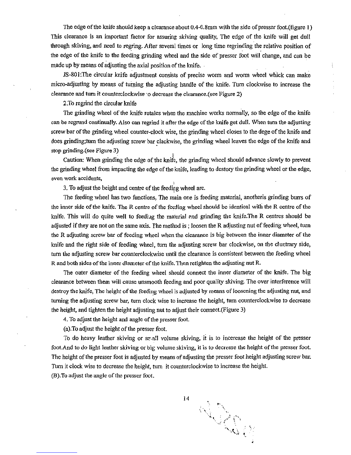
From the library of: Superior Sewing Machine & Supply LLC