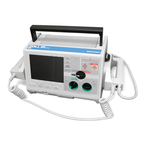
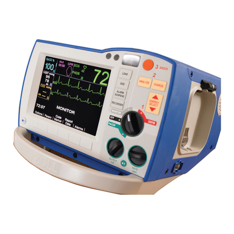
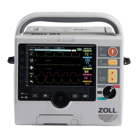
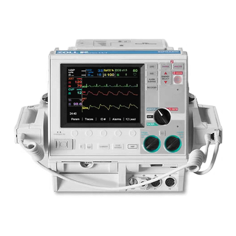
ZOLL M Series User manual

ZOLL M SERIES SERVICE MANUAL
Non-Invasive
Blood Pressure
9653-0455-01 Rev. B

The issue date or revision level for this operation guide is shown on the front cover.
ZOLL and M Series are trademarks of ZOLL Medical Corporation.
2003 by ZOLL Medical Corporation. All rights reserved.

5HY% =2//0 6HULHV6HUYLFH0DQXDO L
Table of Contents
35()$ ( ,,,
RQYHQWLRQV LLL
6DIHW\ RQVLGHUDWLRQV LY
7HFKQLFDO6HUYLFH Y
35,1 ,3/(62)23(5$7,21
1,%3PRGXOH
%ORRGSUHVVXUHPHDVXUHPHQWV
1,%3FRQILJXUDWLRQ
0$,17(1$1 (352 ('85(6
5HTXLUHGHTXLSPHQW
5HFRUGLQJ\RXUUHVXOWV
1,%30RQLWRU7HVW
1,%39ROXPH/HDN7HVW
1,%37UDQVGXFHU DOLEUDWLRQ
',6$66(0%/<352 ('85(6
5HPRYLQJWKH1,%30RGXOH
'LVDVVHPEOLQJWKH1,%30RGXOH
5HPRYLQJWKH1,%3,QWHUIDFH DEOH
5(3/$ (0(173$576
2UGHULQJUHSODFHPHQWSDUWV
3DUWVDQGSDUWQXPEHUV
7528%/(6+227,1*

121,19$6,9(%/22'35(6685(
LL ZZZ]ROOFRP 5HY%

3UHIDFH
5HY% =2//0 6HULHV6HUYLFH0DQXDO LLL
3UHIDFH
ZOLL Medical Corporation’s M Series Service Manual is intended for the service technician
whose responsibility is to identify malfunctions and make repairs at the subassembly level.
Place this insert into the three-ring binder containing the M Series Service Manual and all
other M Series option inserts.
This document provides information required for maintenance of the Non-Invasive Blood
Pressure (NIBP) option on the M Series unit, and contains the following sections:
Principles of Operation on page 1 — provides a general overview of NIBP functionality.
Maintenance Procedures on page 4 — describes procedures for verifying NIBP operation
and integrity.
Disassembly Procedures on page 11 — describes procedures for removing the NIBP
module from the M Series unit.
Replacement Parts on page 21 — lists the field-replaceable parts for the NIBP option and
provides information on ordering replacement parts from ZOLL.
Troubleshooting on page 22 — describes all error messages related to NIBP functionality
and their corresponding corrective action.
In addition, this document contains a copy of the ZOLL M Series Maintenance Test
Checklist. Replace the current checklist in the M Series Service Manual with the checklist
found at the back of this document.
RQYHQWLRQV
This M Series Service Manual uses the following conventions:
Note: Notes contain additional information on using the defibrillator.
$GGLWLRQDO0 6HULHVGRFXPHQWDWLRQ
For more information on M Series operation, see the following documents:
•Non-Invasive Blood Pressure (part number 9650-0214-01), insert to the M Series Operator’s
Guide —describes user tasks for operating the NIBP option on the M Series unit.
•M Series Operator’s Guide (part number 9650-0200-01) — describes all the user tasks for
general operation of the M Series unit.
•M Series Configuration Guide (part number 9650-0201-01) —describes the M Series features
and functions whose operation can be customized by authorized users.
WARNING! Warning statements describe conditions or actions that can result in
personal injury or death.
CAUTION Caution statements describe conditions or actions that can result in damage
to the unit.

121,19$6,9(%/22'35(6685(
LY ZZZ]ROOFRP 5HY%
6DIHW\ RQVLGHUDWLRQV
Service technicians should review these safety considerations prior to servicing any equipment
and read the manual carefully before attempting to disassemble the unit. Only qualified personnel
should service the M Series unit.
Federal (U.S.A.) law restricts this unit for use by or on the order of a physician.
1RQ=2//PDQXIDFWXUHGDFFHVVRULHV
Safety and effectiveness data submitted by ZOLL Medical Corporation to the Food and
Drug Administration (FDA) under section 510(K) of the Medical Device Act to obtain
approval to market is based upon the use of ZOLL accessories such as disposable
electrodes, patient cables and batteries. The use of external pacing/defibrillation electrodes
and adapter units from sources other than ZOLL is not recommended.
ZOLL makes no representations or warranties regarding the performance or effectiveness
of its products when used in conjunction with pacing/defibrillation electrodes and adapter
units from other sources. If unit failure is attributable to pacing/defibrillation electrodes or
adapter units not manufactured by ZOLL, this may void ZOLL's warranty.
:DUQLQJV
All persons near the equipment must be warned to “STAND CLEAR” prior to discharging
the defibrillator.
Do not discharge the unit’s energy internally more than three times in one minute or
damage to the unit may result.
Do not discharge a battery pack except in a Base PowerCharger4x4, a compatible ZOLL
Battery Charging/Testing unit, or an M Series unit.
Do not use the M Series in the presence of flammable agents (such as gasoline),
oxygen-rich atmospheres, or flammable anesthetics. Using the unit near the site of a
gasoline spill may cause an explosion.
Do not use the unit near or within puddles of water.
5DGLR)UHTXHQF\,QWHUIHUHQFH5),
The M Series is protected against interference from radio frequency emissions typical of
two-way radios and cellular phones (digital and analog) used in emergency service/public
safety activities.
Users of the M Series should assess the unit’s performance in their typical environment of
use for the possibility of radio frequency interference from high-power sources. Radio
Frequency Interference (RFI) may be observed as shifts in monitor baseline, trace
compression, or transient spikes on the display.
WARNING! The M Series unit can generate up to 4500 volts with sufficient current
to cause lethal shocks.
3UHIDFH
5HY% =2//0 6HULHV6HUYLFH0DQXDO Y
7HFKQLFDO6HUYLFH
For terms and conditions associated with your warranty, consult your purchasing agreement
(for customers in North America) or a ZOLL authorized representative (for customers
outside North America).
To maintain this warranty, the instructions and procedures contained in this manual must
be strictly followed. For more information, please contact ZOLL Medical Corporation at
1-978-421-9655 or the ZOLL Technical Service Department at 1-800-348-9011 (North
America).
&RQWDFWLQJ7HFKQLFDO6HUYLFH
If the M Series unit requires service, contact the ZOLL Technical Service Department:
Telephone: 1-800-348-9011
1-978-421-9655
FAX: 1-978-421-0010
When requesting service for the M Series unit, please provide the following information
available to the Technical Service representative:
•unit serial number
•description of the problem
•department using the equipment
•sample chart recorder strips documenting the problem, if applicable
•purchase order to allow tracking of loan equipment
•purchase order for a unit with an expired warranty
5HWXUQLQJDXQLWIRUVHUYLFH
If you need to send the unit to ZOLL Medical Corporation for repair, you must obtain a
service request (SR) number from the Technical Service representative. Units are available
on loan while your unit is being repaired.
For customers ... Return the unit in its original container to ...
LQWKH86$ =2//0HGLFDO RUSRUDWLRQ
0LOO5RDG
KHOPVIRUG0$
$WWHQWLRQ 7HFKQLFDO6HUYLFH'HSDUWPHQW65QXPEHU
LQ DQDGD =2//0HGLFDO DQDGD
8QLW
*HQHUDO5RDG
0LVVLVVDXJD2QWDULR
/:=
$WWHQWLRQ7HFKQLFDO6HUYLFH'HSDUWPHQW65QXPEHU
RXWVLGH1RUWK$PHULFD WKHQHDUHVWDXWKRUL]HG=2//0HGLFDO RUSRUDWLRQ6HUYLFH
HQWHU
7RORFDWHDQDXWKRUL]HGVHUYLFHFHQWHUFRQWDFWWKH
,QWHUQDWLRQDO6DOHV'HSDUWPHQWDW=2//0HGLFDODWWKH
DERYHQRWHGDGGUHVV

121,19$6,9(%/22'35(6685(
YL ZZZ]ROOFRP 5HY%

3ULQFLSOHVRI2SHUDWLRQ
5HY% =2//0 6HULHV6HUYLFH0DQXDO
3ULQFLSOHVRI2SHUDWLRQ
The Non-Invasive Blood Pressure (NIBP) option on the M Series provides non-invasive
monitoring of blood pressure and pulse rate for adult and pediatric patients using the
oscillometric method. The NIBP option functions in automatic interval, manual, and STAT
modes.
1,%3PRGXOH
The NIBP module resides in the lower housing assembly of the M Series unit. The patient
blood pressure cuff and hose connect to the M Series unit through the NIBP connector on
the front of the NIBP module. The NIBP button on the front panel of the M Series allows
the user to initiate and terminate blood pressure measurements, which the M Series then
displays in the NIBP display area on the monitor. The user can also initiate and terminate
measurements from the NIBP softkey menu.
Figure 1-1: M Series with NIBP option
1,%3FRPSRQHQWV
The NIBP module itself contains the following components:
•NIBP system board
•pump
•tubing assembly (single lumen)
•power supply board
•NIBP connector
These components measure the oscillometric pulses transmitted through the blood
pressure cuff and hose, calculate blood pressure measurements accordingly, and transmit
them to the main M Series unit.
PACER
RATE
ppm
PACER
OUTPUT
mA
PACER
OFF
MONITOR
DEFIB
1
3
SHOCK
4:1
LEAD
RECORDER
SIZE
ALARM
SUSPEND
CHARGERONSUMMARYCODE
MARKERNIBP
2
ANALYZE
CHARGE
ENERGY
SELECT
24
Param Wave 2Alarms 12Lead
ID#
00:15
NIBP
100
120
80
mmHg
SpO2%
98
CO2
38
m
m
Hg
24
RR
ECG
II 120
x2
MONITOR
ECG
NIBP
connector
NIBP
button
NIBP display
area
NIBP hose
blood
pressure cuff

121,19$6,9(%/22'35(6685(
ZZZ]ROOFRP 5HY%
Figure 1-2: NIBP module assembly
%ORRGSUHVVXUHPHDVXUHPHQWV
The NIBP module measures systolic, diastolic and mean arterial blood pressure in adult and
pediatric patients, and calculates patient pulse rate (PR).
The M Series with NIBP option can take
•a single blood pressure measurement,
•STAT measurements (as many measurements as possible within a five-minute period, to a
maximum of ten), or
•repeated blood pressure measurements at user-configurable intervals.
0HDVXUHPHQWF\FOH
The M Series NIBP module measures arterial blood pressure oscillometrically. The blood
pressure measurement cycle takes approximately 30 seconds, and proceeds as follows:
power supply
board
NIBP system
board
tubing
pump
NIBP connector
Stage Description
7KHLQWHUQDOSXPSLQIODWHVWKHFXIIWRDSUHFRQILJXUHGSUHVVXUHFRQILJXUHGGHIDXOWYDOXHLV
PP+JW\SLFDOO\DERYHWKHSDWLHQW¶VV\VWROLFEORRGSUHVVXUHWRRFFOXGHEORRGIORZLQ
WKHPRQLWRUHGOLPE
7KHFXIIGHIODWHVDXWRPDWLFDOO\LQVWDJHVWRDOORZEORRGWRIORZSDVWWKHFXIILQWKH
PRQLWRUHGOLPE
$VEORRGIORZUHVXPHVSDVWWKHFXIILWSURGXFHVSUHVVXUHRVFLOODWLRQVWKDWDUHWUDQVPLWWHG
WRWKH0 6HULHVXQLWWKURXJKWKHKRVH
7KH1,%3V\VWHPERDUGPHDVXUHVWKHRVFLOORPHWULFSXOVHVDQGXVHVWKHPWRFDOFXODWHWKH
FRUUHVSRQGLQJV\VWROLFGLDVWROLFDQGPHDQEORRGSUHVVXUHDVZHOODVWKHSDWLHQW¶VSXOVH
UDWH

3ULQFLSOHVRI2SHUDWLRQ
5HY% =2//0 6HULHV6HUYLFH0DQXDO
See the M Series Operator’s Guide insert for Non-Invasive Blood Pressure for details on
operating the NIBP option.
1,%3FRQILJXUDWLRQ
You can change default settings for NIBP parameters such as units of measurement, initial
cuff inflation, automatic measurement intervals, and alarm thresholds. See the M Series
Configuration Guide for more information.
7KH0 6HULHVGLVSOD\VWKHEORRGSUHVVXUHYDOXHVRQWKHPRQLWRU
+RZHYHU
•LIWKH1,%3VHQVRUFDQQRWGHWHFWV\VWROLFSUHVVXUHWKH0 6HULHVDXWRPDWLFDOO\
LQFUHDVHVWKHFXIILQIODWLRQSUHVVXUHDQGFRPSOHWHVWKHEORRGSUHVVXUHPHDVXUHPHQW
•LIWKH0 6HULHVFDQQRWGHWHFWV\VWROLFGLDVWROLFRUPHDQSUHVVXUHDIWHU VHFRQGVWKH
XQLWDERUWVWKHEORRGSUHVVXUHPHDVXUHPHQWDQGGHIODWHVWKHFXII
•LIWKH0 6HULHVGHWHFWVDIDXOWWKHXQLWGLVSOD\VDFRUUHVSRQGLQJHUURUPHVVDJHRQWKH
PRQLWRUDQGDERUWVWKHPHDVXUHPHQW
Note: ,QDXWRPDWLFLQWHUYDOPRGHWKH0 6HULHVGRHVQRWLQLWLDWHDQHZPHDVXUHPHQWXQWLO
VHFRQGVKDYHHODSVHGVLQFHWKHHQGRIWKHODVWFRPSOHWHGPHDVXUHPHQWF\FOH
Stage Description

121,19$6,9(%/22'35(6685(
ZZZ]ROOFRP 5HY%
0DLQWHQDQFH3URFHGXUHV
It is important that users conduct the Operator’s Shift Checklist procedure at the beginning
of every shift to maintain the M Series unit ready for immediate use. This checkout
procedure can be completed in a few minutes and requires no additional test equipment.
See the M Series Operator’s Guide for the Operator’s Shift Checklist.
For the NIBP option, a qualified biomedical technician should perform the following
maintenance procedures every six months to ensure that the M Series NIBP function is
operating properly:
•“NIBP Monitor Test” on page 5
•“NIBP Volume Leak Test” on page 6 (optional at 6 months, recommended annually)
•“NIBP Transducer Calibration” on page 8 (optional at 6 months, recommended annually)
5HTXLUHGHTXLSPHQW
You need the following equipment to complete each NIBP maintenance procedure:
•M Series unit with NIBP option (with fully-charged battery installed)
•Bio-Tek BP Pump NIBP Monitor Analyzer (or equivalent)
Note: For all NIBP maintenance tests, ensure that the ECG cable is not connected to the
M Series unit. If the SpO2option is installed, make sure that the Masimo cable is
NOT connected to the M Series unit
5HFRUGLQJ\RXUUHVXOWV
Photocopy the checklist at the back of the M Series Service Manual and use the copy to record
the results of the maintenance tests.
As you complete each step in a procedure, mark the appropriate Pass/Fail/NA box, and
keep the checklist for your maintenance file. Complete all the steps of the procedure before
evaluating the test results.

0DLQWHQDQFH3URFHGXUHV
5HY% =2//0 6HULHV6HUYLFH0DQXDO
1,%30RQLWRU7HVW
The NIBP monitor test verifies the accuracy of the systolic, diastolic and mean blood
pressure measurements, as well as patient pulse rate calculation.
%HIRUH\RXEHJLQ
Before you begin the NIBP monitor test:
•Connect the NIBP Analyzer’s simulator hose to the NIBP connector on the M Series unit.
•Set the following parameters on the NIBP Analyzer:
3URFHGXUH
Follow these steps to perform the NIBP monitor test:
Parameter Value
6\VWROLFSUHVVXUH PP+J
'LDVWROLFSUHVVXUH PP+J
0HDQSUHVVXUH PP+J
+HDUWUDWH ESP
Step Action Expected Result
19.1 6HWWKHVHOHFWRUVZLWFKRQWKH0 6HULHVXQLW
WR021,725)RU$('XQLWVWXUQWKH
VHOHFWRUVZLWFKWR21DQGVHOHFW0DQXDO
PRGH
7KH0 6HULHVSRZHUVRQLQ021,725PRGH
19.2 (QVXUHWKDWWKH/($'6SDUDPHWHULVVHWWR
3$'6GHIDXOWYDOXH
<RXFDQF\FOHWKURXJKWKHYDOXHVIRUWKH
/($'6SDUDPHWHUWR3$'6E\SUHVVLQJWKH
/($'EXWWRQ
7KH0 6HULHVGLVSOD\V3$'6LQWKH/HDG
VHOHFWLRQILHOGRIWKHPRQLWRU
19.3 3UHVVWKH1,%3EXWWRQRQWKH0 6HULHVIURQW
SDQHO
9HULI\WKDWWKHYDOXHVGLVSOD\HGDUHDFFXUDWH
ZLWKLQ PP+JRIWKHSUHVVXUHSDUDPHWHUV
VHWRQWKH1,%3$QDO\]HU
7KH0 6HULHVLQLWLDWHVWKHEORRGSUHVVXUH
PHDVXUHPHQWF\FOHDQGGLVSOD\VWKHIROORZLQJ
PHDVXUHPHQWV
•V\VWROLFSUHVVXUH PP+J
•GLDVWROLFSUHVVXUH PP+J
•PHDQSUHVVXUH PP+J
19.4 3UHVVWKH6800$5<EXWWRQRQWKH
0 6HULHVIURQWSDQHO
19.5 )RUVRIWZDUHORDGV9DQGORZHUVHOHFW
WKH+LVWRU\VRIWNH\
)RUVRIWZDUHORDGV9DQGKLJKHU
VHOHFWWKH7UHQGVRIWNH\WKHQVHOHFWWKH
1,%37UHQGVRIWNH\
7KH0 6HULHVGLVSOD\VDVXPPDU\RIWKH1,%3
PHDVXUHPHQWVLQFOXGLQJWKHSXOVHUDWH
UHDGLQJLQWKHUDQJHRI ESP
5HFRUG\RXUUHVXOWVRQWKH0DLQWHQDQFH7HVWV KHFNOLVW

121,19$6,9(%/22'35(6685(
ZZZ]ROOFRP 5HY%
1,%39ROXPH/HDN7HVW
The volume leak test verifies the integrity of the pneumatic system on the NIBP module.
This test is optional at six (6) months, but should be performed annually or every
10,000 readings, whichever comes first.
%HIRUH\RXEHJLQ
Before you begin the NIBP volume leak test:
•Connect the NIBP Analyzer’s simulator hose to the NIBP connector on the M Series unit.
•Configure the NIBP Analyzer for the volume leak test. For example, on the Bio-Tek BP
Pump:
➯Press the MODE button three (3) times to go into Tests Mode.
➯Press the SELECT button twice to access the volume leak test.
Note: These instructions apply to the Bio-Tek BP Pump; for equivalent devices, follow the
manufacturer’s instructions.
3URFHGXUH
Follow these steps to perform the NIBP volume leak test on the M Series unit.
Step Action Expected Result
20.1 7XUQWKHVHOHFWRUVZLWFKWR2))
$IWHU VHFRQGVSUHVVDQGKROGWKHIRXUWK
VRIWNH\IURPWKHOHIWDQGWXUQWKHVHOHFWRU
VZLWFKWR021,725
7KH0 6HULHVSRZHUVRQLQ1,%36HUYLFH
0RGH
20.2 3UHVVWKH/HDN7HVWVRIWNH\ 7KH0 6HULHVGLVSOD\VWKH1,%3/HDN7HVW
VFUHHQ
20.3 2QWKH1,%3$QDO\]HUVHWWKHSUHVVXUH
SDUDPHWHUWR PP+J
7KH1,%3$QDO\]HUGLVSOD\VDSUHVVXUH
UHDGLQJRI PP+J
Leak
Test
NIBP
Calib
NIBP Service Mode
Exit
Open
Valves
Close
Valves Exit
NIBP Leak Test
Valves
Cuff Pressure
OPEN
0

0DLQWHQDQFH3URFHGXUHV
5HY% =2//0 6HULHV6HUYLFH0DQXDO
20.4 2QWKH0 6HULHVXQLWSUHVVWKH&ORVH
9DOYHVVRIWNH\
7KH³9DOYHV´VWDWXVFKDQJHVIURP23(1WR
/26('
20.5 2QWKH1,%3$QDO\]HUSUHVVWKH67$57
7(67VRIWNH\
Note: <RXPXVWSUHVVWKH67$577(67
VRIWNH\ZLWKLQ VHFRQGVRIFORVLQJ
WKHYDOYHVRQWKH0 6HULHVXQLW
$IWHUDSSUR[LPDWHO\ PLQXWHDQXPEHU
DSSHDUVLQWKHXSSHUPLGGOHDUHDRIWKH1,%3
$QDO\]HUGLVSOD\
IF the NIBP Analyzer ... THEN ...
GLVSOD\VD9ROXPH/HDN
UHDGLQJ≤
WKHXQLWKDV
SDVVHGWKHWHVW
GLVSOD\VD9ROXPH/HDN
UHDGLQJ!
WKHXQLWKDV
IDLOHGWKHWHVW
GLVSOD\VQR9ROXPH/HDN
UHDGLQJEXWPDLQWDLQVD
VWDEOHSUHVVXUHUHDGLQJDW
RUDERYH PP+J
WKHXQLWKDV
SDVVHGWKHWHVW
WKHUHLVQR
YROXPHOHDN
,QDGGLWLRQWKH0 6HULHVGLVSOD\VWKH
$QDO\]HU¶VSUHVVXUHUHDGLQJLQWKH
³ XII 3UHVVXUH´ILHOG
$IWHUDSSUR[LPDWHO\ PLQXWHVWKHYDOYHVRQ
WKH0 6HULHVXQLWRSHQ
20.6 2QWKH1,%3$QDO\]HUSUHVVWKH6723
7(67VRIWNH\
7KH1,%3$QDO\]HUWHUPLQDWHVWKH9ROXPH
/HDN7HVW
20.7 2QWKH0 6HULHVXQLWSUHVVWKH(;,7
VRIWNH\WZLFH
7KH0 6HULHVUHWXUQVWRWKHPDLQ1,%3
6HUYLFH0RGHVFUHHQWKHQWRQRUPDO0RQLWRU
PRGHRSHUDWLRQ
5HFRUG\RXUUHVXOWVRQWKH0DLQWHQDQFH7HVWV KHFNOLVW
Step Action Expected Result
Open
Valves
Close
Valves Exit
NIBP Leak Test
Valves
Cuff Pressure
CLOSED
0

121,19$6,9(%/22'35(6685(
ZZZ]ROOFRP 5HY%
1,%37UDQVGXFHU DOLEUDWLRQ
The NIBP module’s pressure transducers are factory-calibrated prior to shipment.
However, you can perform a two-point calibration procedure periodically to ensure
accurate pressure measurements.
This procedure is optional at six (6) months, but should be performed annually or every
10,000 readings, whichever comes first.
%HIRUH\RXEHJLQ
Before you begin the NIBP transducer calibration procedure:
•Connect the NIBP Analyzer’s simulator hose to the NIBP connector on the M Series unit.
•Configure the NIBP Analyzer to simulate cuff pressure. For example, on the Bio-Tek BP
Pump:
➯Press the MODE button three (3) times to go into Tests Mode.
➯Press the SELECT button once to access the Pressure Simulator screen.
Note: These instructions apply to the Bio-Tek BP Pump; for equivalent devices, follow the
manufacturer’s instructions.
3URFHGXUH
Follow these steps to calibrate the NIBP transducers on the M Series unit.
Step Action Expected Result
21.1 7XUQWKHVHOHFWRUVZLWFKWR2))
$IWHU VHFRQGVSUHVVDQGKROGWKHIRXUWK
VRIWNH\IURPWKHOHIWDQGWXUQWKHVHOHFWRU
VZLWFKWR021,725
7KH0 6HULHVSRZHUVRQLQ1,%36HUYLFH
0RGH
21.2 3UHVVWKH1,%3&DOLEVRIWNH\ 7KH0 6HULHVGLVSOD\VWKH1,%37UDQVGXFHU
DOLEUDWLRQVFUHHQ
21.3 2QWKH1,%3$QDO\]HUVHWWKHSUHVVXUH
SDUDPHWHUWR PP+J
7KH1,%3$QDO\]HUGLVSOD\VDSUHVVXUH
UHDGLQJRI PP+J
Leak
Test
NIBP
Calib
NIBP Service Mode
Exit
Exit
NIBP Transducer Calibration
0 mmHg
250 mmHg
Cuff Pressure
---
---
---
Set
Low

0DLQWHQDQFH3URFHGXUHV
5HY% =2//0 6HULHV6HUYLFH0DQXDO
21.4 2QWKH0 6HULHVXQLWSUHVVWKH6HW/RZ
VRIWNH\WRFDOLEUDWHWKHWUDQVGXFHUWRD
PP+JSUHVVXUHUHDGLQJ
Note: ,IWKH0 6HULHVGLVSOD\VD)$,/
UHDGLQJYHULI\WKH1,%3$QDO\]HU¶V
SUHVVXUHVHWWLQJDQGFRQQHFWLRQWR
WKH0 6HULHVDQGUHSHDWWKHVWHS
7KH1,%3SUHVVXUHWUDQVGXFHUUHJLVWHUVLWV
YROWDJHRXWSXWDWDNQRZQSUHVVXUHRI
PP+J7KHILHOGDGMDFHQWWRWKH PP+J
YDOXHFKDQJHVWR3$66
21.5 2QWKH1,%3$QDO\]HUVHWWKHSUHVVXUH
SDUDPHWHUWR PP+J
7KH1,%3$QDO\]HUGLVSOD\VDSUHVVXUH
UHDGLQJRI PP+J
21.6 2QWKH0 6HULHVXQLWSUHVVWKH6HW+LJK
VRIWNH\WRFDOLEUDWHWKHWUDQVGXFHUWRD
PP+JSUHVVXUHUHDGLQJ
Note: ,IWKH0 6HULHVGLVSOD\VD)$,/
UHDGLQJYHULI\WKH1,%3$QDO\]HU¶V
SUHVVXUHVHWWLQJDQGFRQQHFWLRQWR
WKH0 6HULHVDQGUHSHDWWKHVWHS
7KH1,%3SUHVVXUHWUDQVGXFHUUHJLVWHUVLWV
YROWDJHRXWSXWDWDNQRZQSUHVVXUHRI
PP+J7KHILHOGDGMDFHQWWRWKH
PP+JYDOXHFKDQJHVWR3$66
21.7 2QWKH1,%3$QDO\]HUVHWWKHSUHVVXUH
SDUDPHWHUWRVLPXODWHDGLIIHUHQWFXII
SUHVVXUHIRUH[DPSOH PP+J
7KH1,%3$QDO\]HUGLVSOD\VWKHVSHFLILHG
SUHVVXUHUHDGLQJ
21.8 2QWKH0 6HULHVXQLWSUHVVWKH5HDG&XII
VRIWNH\
9HULI\WKDWWKHYDOXHGLVSOD\HGLVDFFXUDWH
ZLWKLQ PP+JRIWKHSUHVVXUHSDUDPHWHU
VHWRQWKH1,%3$QDO\]HU
7KH1,%3PRGXOHPHDVXUHVWKHSUHVVXUH
IURPWKH1,%3$QDO\]HUDQGGLVSOD\VWKH
YDOXHLQWKH XII 3UHVVXUHILHOG
21.9 2QWKH0 6HULHVXQLWSUHVVWKH([LWVRIWNH\
WZLFH
7KH0 6HULHVUHWXUQVWRWKHPDLQ1,%3
6HUYLFH0RGHVFUHHQWKHQWRQRUPDO0RQLWRU
PRGHRSHUDWLRQ
Step Action Expected Result
Exit
NIBP Transducer Calibration
0 mmHg
250 mmHg
Cuff Pressure
PASS
---
---
Set
High
Exit
NIBP Transducer Calibration
Read
Cuff
PASS
PASS
---
0 mmHg
250 mmHg
Cuff Pressure
Exit
NIBP Transducer Calibration
Read
Cuff
PASS
PASS
205
0 mmHg
250 mmHg
Cuff Pressure

121,19$6,9(%/22'35(6685(
ZZZ]ROOFRP 5HY%
21.10 3HUIRUPWKH1,%30RQLWRU7HVWVHH³1,%3
0RQLWRU7HVW´RQSDJH WRYHULI\IXQFWLRQDO
RSHUDWLRQRIWKH1,%3RSWLRQ
7KH0 6HULHVSDVVHVDOOFULWHULDIRUWKH1,%3
0RQLWRU7HVW
5HFRUG\RXUUHVXOWVRQWKH0DLQWHQDQFH7HVWV KHFNOLVW
:DUQLQJ NIBP transducer calibration can affect clinical readings of the NIBP
parameter. Ensure that the NIBP Transducer Calibration procedure is
performed correctly, followed by an NIBP Monitor Test to verify proper
operation.
Step Action Expected Result

'LVDVVHPEO\3URFHGXUHV
5HY% =2//0 6HULHV6HUYLFH0DQXDO
'LVDVVHPEO\3URFHGXUHV
This section describes the following procedures:
•“Removing the NIBP Module” on page 11
•“Disassembling the NIBP Module” on page 15
•“Removing the NIBP Interface Cable” on page 18
Only properly trained technicians should service the M Series unit. Ensure that you take the
appropriate safety precautions before disassembling any part of the M Series unit.
In addition:
•Discharge the unit before conducting any maintenance or repairs.
•Wear a conductive wrist strap that touches your skin and is connected to a grounding mat
and to an earth ground when working with static-sensitive units. Remove the wrist strap
when you discharge high voltage or when you are working on energized equipment.
5HPRYLQJWKH1,%30RGXOH
The NIBP module resides in the lower housing assembly of the M Series unit and connects
to the main system board through the NIBP interface cable.
5HTXLUHGWRROV
You need the following tools to disassemble the NIBP module:
•#1 Phillips screwdriver
•#2 Phillips screwdriver
•small wood stick
%HIRUH\RXEHJLQ
Remove all power sources, such as the battery and power cord.
:DUQLQJ
SHOCK HAZARD!
Take necessary precautions to guard against shock or injury before
conducting defibrillator tests or repairs. The M Series unit can
contain lethal voltages even when turned off.

121,19$6,9(%/22'35(6685(
ZZZ]ROOFRP 5HY%
3URFHGXUH
Follow these steps to remove the NIBP module from the M Series unit.
Step Action
5RWDWHWKHXQLWRQWRLWVEDFNVLGHVRWKDWWKH
ERWWRPLVIDFLQJ\RX
5HPRYHWKHSDSHUWUD\E\SXOOLQJWKHWUD\RXW
DQGSUHVVLQJLQDQGXSZDUGVRQWKHORFNLQJWDE
DWWKHUHDURIWKHWUD\
5HPRYHWKH3KLOOLSVVFUHZEHQHDWKWKH
3 0 ,$ )$;PRGHPVORWRQWKHULJKWVLGHRI
WKHXQLW
5HPRYHWKHSODVWLFEH]HOFRYHULQJWKH3 0 ,$
)$;PRGHPVORW
,ILQVWDOOHGUHPRYHWKH3 0 ,$)$;PRGHP
FDUGIURPWKHXQLW
Other manuals for M Series
13
Table of contents
Other ZOLL Medical Equipment manuals

ZOLL
ZOLL Quattro IC-4593AE/8700-0783-40 User manual

ZOLL
ZOLL Aed Plus Service manual

ZOLL
ZOLL Aed Plus Manual

ZOLL
ZOLL M Series User manual

ZOLL
ZOLL Propaq MD Manual

ZOLL
ZOLL M Series User manual

ZOLL
ZOLL Cool Line CL-2295AE/8700-0781-40 User manual

ZOLL
ZOLL Aed Plus User manual

ZOLL
ZOLL Aed Plus Manual

ZOLL
ZOLL Aed Plus Service manual