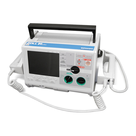
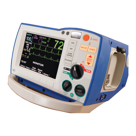
ZOLL M Series User manual

ZOLL M SERIES SERVICE MANUAL
Invasive Blood
Pressure
5HY%

The issue date or revision level for this operation guide is shown on the front cover.
ZOLL and M Series are trademarks of ZOLL Medical Corporation.
2003 by ZOLL Medical Corporation. All rights reserved.

5HY% =2//0 6HULHV6HUYLFH0DQXDO L
Table of Contents
35() &( ,,,
&RQYHQWLRQV LLL
6DIHW\&RQVLGHUDWLRQV LY
7HFKQLFDO6HUYLFH Y
35,1&,3/(62)23(5 7,21
%ORRGSUHVVXUHPHDVXUHPHQWV
,%3FRQILJXUDWLRQ
0,17(1 1&(7(676
5HFRUGLQJ\RXUUHVXOWV
7HVWVHWXS
,%30RQLWRU7HVW
,%31RLVH7HVW
,%36WDWLF3UHVVXUH7HVW
',6 66(0%/<352&('85(6
'LVDVVHPEOLQJWKH,%3PRGXOH
5(3/ &(0(173 576
2UGHULQJUHSODFHPHQWSDUWV
3DUWVDQGSDUWQXPEHUV
7528%/(6+227,1*

,19 6,9(%/22'35(6685(
LL ZZZ]ROOFRP 5HY%

3UHIDFH
5HY% =2//0 6HULHV6HUYLFH0DQXDO LLL
3UHIDFH
ZOLL Medical Corporation’s M Series Service Manual is intended for the service technician
who identifies malfunctions and makes repairs at the subassembly level. Place this insert
into the three-ring binder containing the M Series Service Manual and all other M Series
option inserts.
This document provides information required for maintenance of the Invasive Blood
Pressure (IBP) option on the M Series CCT unit, and contains the following sections:
Principles of Operation on page 1 — provides a general overview of IBP functionality.
Maintenance Tests on page 3 — describes procedures for verifying IBP operation and
integrity.
Disassembly Procedures on page 12 — describes the procedure for removing the IBP
assembly from the M Series CCT unit.
Replacement Parts on page 16 — lists the field-replaceable parts for the IBP option and
provides information on ordering replacement parts from ZOLL.
Troubleshooting on page 17 — describes error messages related to IBP functionality and
their corresponding corrective action.
&RQYHQWLRQV
This M Series Service Manual insert uses the following conventions:
Note: Notes contain additional information on using and maintaining the M Series unit.
$GGLWLRQDO0 6HULHVGRFXPHQWDWLRQ
For more information on M Series operation and configuration, see the following
documents:
•Invasive Blood Pressure insert (part number 9650-0219-01) of the M Series Operator’s Guide —
describes user tasks for operating the IBP option.
•M Series Operator’s Guide (part number 9650-0200-01) — describes user tasks for general
operation of the M Series unit.
•M Series Configuration Guide (part number 9650-0201-01) —describes M Series features and
functions whose operation can be customized by authorized users.
WARNING! Warning statements describe conditions or actions that can result in
personal injury or death.
CAUTION Caution statements describe conditions or actions that can result in damage
to the unit.

,19 6,9(%/22'35(6685(
LY ZZZ]ROOFRP 5HY%
6DIHW\&RQVLGHUDWLRQV
Service technicians should review these safety considerations prior to servicing any
equipment and read the manual carefully before attempting to disassemble the unit. Only
qualified personnel should service the M Series unit.
Federal (U.S.A.) law restricts this unit for use by or on the order of a physician.
1RQ=2//PDQXIDFWXUHGDFFHVVRULHV
Safety and effectiveness data submitted by ZOLL Medical Corporation to the Food and
Drug Administration (FDA) under section 510(K) of the Medical Device Act to obtain
approval to market is based on the use of ZOLL accessories such as disposable electrodes,
patient cables and batteries. The use of external pacing/defibrillation electrodes and
adapter units from sources other than ZOLL is not recommended.
ZOLL makes no representations or warranties regarding the performance or effectiveness
of its products when used in conjunction with pacing/defibrillation electrodes and adapter
units from other sources. If unit failure is attributable to pacing/defibrillation electrodes or
adapter units not manufactured by ZOLL, this may void ZOLL's warranty.
:DUQLQJV
All persons near the equipment must be warned to “STAND CLEAR” prior to discharging
the defibrillator.
Do not discharge the M Series unit’s energy internally more than three times in one minute
or damage to the unit may result.
Do not discharge a battery pack except in a Base PowerCharger4x4, a compatible ZOLL
Battery Charging/Testing unit, or an M Series unit.
Do not use the M Series unit in the presence of flammable agents (such as gasoline),
oxygen-rich atmospheres, or flammable anesthetics. Using the unit near the site of a
gasoline spill may cause an explosion.
Do not use the M Series unit near or within puddles of water.
5DGLR)UHTXHQF\,QWHUIHUHQFH5),
The M Series unit is protected against interference from radio frequency emissions typical
of two-way radios and cellular phones (digital and analog) used in emergency service/public
safety activities.
Users of the M Series should assess the unit’s performance in their typical environment of
use for the possibility of radio frequency interference from high-power sources. Radio
Frequency Interference (RFI) may be observed as shifts in monitor baseline, trace
compression, or transient spikes on the display.
:DUQLQJ
SHOCK HAZARD!
The M Series CCT unit can generate up to 2400 volts with
sufficient current to cause lethal shocks.
3UHIDFH
5HY% =2//0 6HULHV6HUYLFH0DQXDO Y
7HFKQLFDO6HUYLFH
For terms and conditions associated with your warranty, consult your purchasing agreement
(for customers in North America) or a ZOLL authorized representative (for customers
outside North America).
To maintain this warranty, the instructions and procedures contained in this manual must
be strictly followed. For more information, please contact ZOLL Medical Corporation’s
Technical Service Department at 1-800-348-9011 (North America). If calling from outside
North America, contact ZOLL Medical Corporation headquarters at 1-978-421-9655.
&RQWDFWLQJ7HFKQLFDO6HUYLFH
If the M Series unit requires service, contact the ZOLL Technical Service Department:
Telephone: 1-800-348-9011
1-978-421-9655
FAX: 1-978-421-0010
When requesting service for the M Series unit, please provide the following information to
the Technical Service representative:
•unit serial number
•description of the problem
•department using the equipment
•sample chart recorder strips documenting the problem, if applicable
•purchase order to allow tracking of loan equipment
•purchase order for a unit with an expired warranty
5HWXUQLQJDXQLWIRUVHUYLFH
If you need to send the unit to ZOLL Medical Corporation for repair, you must obtain a
service request (SR) number from the Technical Service representative. Units are available
on loan while your unit is being repaired.
For customers ... Return the unit in its original container to ...
LQWKH86$ =2//0HGLFDO& US UDWL Q
0LOO5 DG
&KHOPVI UG0$
$WWHQWL Q 7HFKQLFDO6HUYLFH'HSDUWPHQW65QXPEHU
LQ&DQDGD =2//0HGLFDO&DQDGD
8QLW
*HQHUDO5 DG
0LVVLVVDXJD2QWDUL
/:=
$WWHQWL Q 7HFKQLFDO6HUYLFH'HSDUWPHQW65QXPEHU
XWVLGH1 UWK$PHULFD WKHQHDUHVWDXWK UL]HG=2//0HGLFDO& US UDWL Q6HUYLFH
&HQWHU
7 O FDWHDQDXWK UL]HGVHUYLFHFHQWHUF QWDFWWKH
,QWHUQDWL QDO6DOHV'HSDUWPHQWDW=2//0HGLFDODWWKH
DE YHQ WHGDGGUHVV

,19 6,9(%/22'35(6685(
YL ZZZ]ROOFRP 5HY%

3ULQFLSOHVRI2SHUDWLRQ
5HY% =2//0 6HULHV6HUYLFH0DQXDO
3ULQFLSOHVRI2SHUDWLRQ
The Invasive Blood Pressure (IBP) option on the M Series CCT unit allows for invasive
monitoring of arterial (ART), pulmonary arterial (PA), central venous (CV), and
intracranial (ICP) pressures on two channels. The M Series CCT unit displays systolic,
diastolic, and mean pressure measurements, and displays up to two IBP waveforms along
with one ECG trace.
The IBP/Temperature module resides in the lower housing assembly of the M Series CCT
unit. A transducer connects to the M Series CCT unit through one of two pressure channel
connectors on the front of the unit.
Figure 1-1: M Series with IBP option
You can assign labels to each pressure channel to indicate the type of pressure being
measured. You can also assign each IBP waveform to a trace position on the
M Series CCT display, and set the amplitude scale for displaying the waveform.
See the Invasive Blood Pressure insert of the M Series Operator’s Guide for details on operating
the IBP option.
%ORRGSUHVVXUHPHDVXUHPHQWV
The M Series IBP function measures systolic, diastolic, and mean pressure by processing
electrical signals from a resistive bridge transducer with 5 µV/V/mmHg sensitivity
connected to the patient through a catheter.
Note: Transducers with 40 µV/V/mmHg sensitivity are NOT compatible with the
MSeriesCCTuni
t.
Pulsatile pressures (ART, PA, P1) display systolic, diastolic, and mean values. Non-pulsatile
pressures (CVP, ICP, P2) display mean values only.
PACER
RATE
ppm
PACER
OUTPUT
mA
PACER
CHARGER ON
OFF
MONITOR
DEFIB
1
3
SHOCK
4:1
LEAD
RECORDER
SIZE
ALARM
SUSPEND
SUMMARY CODE
MARKER NIBP
2
ANALYZE
CHARGE
ENERGY
SELECT
NIBP
107
128
98
SpO2%
98
ECG
x2 120
II
ECG
CO2
RR
100
24
mmHg
P1
110
mmHg
130
100
P2
mmHg
12
T1
99.1
°F
Param Traces Alarms12 Lead
ID#
00:01
P2
P1
0
120
0
180
mmHg
NIBP
T1/T2
P1 P2
P1 display area
IBP waveform display
P2 display area
IBP connectors

,19 6,9(%/22'35(6685(
ZZZ]ROOFRP 5HY%
When the M Series CCT unit detects a connection to a transducer through one or both of
the pressure channel connectors, the unit prompts the user to zero the pressure channel(s).
Pressure measurement does not begin until the pressure channels have been zeroed.
The IBP measurement cycle proceeds as follows:
,%3FRQILJXUDWLRQ
You can change default settings for IBP parameters such as pressure channel labels and
waveform display scale at power-up, and alarm thresholds. See the M Series Configuration
Guide for more information.
Stage Description
FDWKHWHULVLQVHUWHGLQWRWKHSDWLHQW¶VYDVFXODWXUHSHUWKHLQVWLWXWLRQ¶VSURWRFROVDQGLV
FRXSOHGWRDWUDQVGXFHUWKURXJKDIOXLGILOOHGOHQJWKRIWXELQJ7KHWUDQVGXFHUFRQQHFWVWR
RQHRIWZRSUHVVXUHFKDQQHOFRQQHFWRUVRQWKH0 6HULHV&&7XQLWWKURXJKDQLQWHUIDFH
FDEOH
1RWH QDGDSWHUFDEOHPD\EHXVHGWRFRQQHFWWKHLQWHUIDFHFDEOHIURPDGLIIHUHQW
PRQLWRUWRWKH0 6HULHV&&7XQLW
3UHVVXUHIOXFWXDWLRQVWUDYHOWKURXJKWKHIOXLGLQWKHFDWKHWHUWXELQJWRWKHWUDQVGXFHU
FDXVLQJWKHWUDQVGXFHU¶VGLDSKUDJPWRPRYHVOLJKWO\LQUHVSRQVH
7KHGLDSKUDJPPRYHPHQWVFUHDWHDFKDQJHLQUHVLVWDQFHZKLFKWKHWUDQVGXFHUFRQYHUWV
WRDQHOHFWULFDOVLJQDODQGVHQGVWRWKH0 6HULHV&&7XQLWWKURXJKWKHLQWHUIDFHFDEOH
7KH0 6HULHV&&7XQLWXVHVWKHHOHFWULFDOVLJQDOIURPWKHWUDQVGXFHUWRFDOFXODWHWKH
FRUUHVSRQGLQJSUHVVXUHYDOXHVDQGGLVSOD\DZDYHIRUP
7KH0 6HULHV&&7XQLWGLVSOD\VWKHQXPHULFSUHVVXUHYDOXHVRQWKHPRQLWRUDQGWKH
DVVRFLDWHGZDYHIRUPLIFRQILJXUHG

0DLQWHQDQFH7HVWV
5HY% =2//0 6HULHV6HUYLFH0DQXDO
0DLQWHQDQFH7HVWV
It is important that users conduct the Operator’s Shift Checklist procedure at the beginning
of every shift to maintain the M Series unit ready for immediate use. This checkout
procedure can be completed in a few minutes and requires no additional test equipment.
See the M Series Operator’s Guide for the Operator’s Shift Checklist.
For the IBP option, a qualified biomedical technician should perform the following
maintenance procedures every six months to ensure that the M Series IBP function is
operating properly:
•“IBP Monitor Test” on page 5
•“IBP Noise Test” on page 7
•“IBP Static Pressure Test” on page 10
5HFRUGLQJ\RXUUHVXOWV
Photocopy the checklist at the back of the M Series Service Manual and use the copy to record
the results of the maintenance tests. As you complete each step in a procedure, mark the
appropriate Pass/Fail/NA box, and keep the checklist for your maintenance file. Complete
all the steps of the procedure before evaluating the test results.
7HVWVHW X S
Follow these steps to prepare the M Series CCT unit for the IBP maintenance tests.
Step Action Expected Result
6HWWKHVHOHFWRUVZLWFKRQWKH0 6HULHV&&7
XQLWWR021,725
7KH06HULHV&&7XQLWSRZHUVRQLQ
021,725PRGH
3UHVVWKH3DUDPVRIWNH\RQWKHIURQWSDQHO
WRGLVSOD\WKH3DUDPHWHUVPHQX
7KH06HULHV&&7XQLWGLVSOD\VWKH
3DUDPHWHUVPHQX
6HOHFWWKH,%3RSWLRQDQGSUHVVWKH(QWHU
VRIWNH\
7KH06HULHV&&7XQLWGLVSOD\VWKH,%3
PHQX
3UHVVWKH/DEHOVRIWNH\WRGLVSOD\WKH,%3
/DEHOPHQX
7KH06HULHV&&7XQLWGLVSOD\VWKH,%3/DEHO
PHQX
Select Enter Return
IBP
NIBP
EtCO2
SpO2
Zero Range Return
Label
Select Enter Return
Label P1
Label P2

,19 6,9(%/22'35(6685(
ZZZ]ROOFRP 5HY%
6HOHFWWKH/DEHO3RSWLRQDQGSUHVVWKH
(QWHUVRIWNH\
7KH06HULHV&&7XQLWGLVSOD\VWKH/DEHO
2SWLRQVPHQX
6HOHFWWKH3RSWLRQDQGSUHVVWKH(QWHU
VRIWNH\
7KH06HULHV&&7XQLWDVVLJQVWKH3ODEHOWR
WKHILUVWSUHVVXUHFKDQQHO3DQGUHWXUQVWR
WKH,%3PHQX
5HSHDWVWHSVWKURXJKWRDVVLJQWKH$57
DUWHULDOSUHVVXUHODEHOWRWKHVHFRQG
SUHVVXUHFKDQQHO3
7KH06HULHV&&7XQLWDVVLJQVWKH 57ODEHO
WRWKHVHFRQGSUHVVXUHFKDQQHO3DQG
UHWXUQVWRWKH,%3PHQX
Step Action Expected Result
Select Enter Return
ART
PA
CVP
ICP
P1
P1
-----
mmHg
-----
-----
ART mmHg
-----
-----
-----

0DLQWHQDQFH7HVWV
5HY% =2//0 6HULHV6HUYLFH0DQXDO
,%30RQLWRU7HVW
The IBP monitor test verifies proper pressure channel zeroing and the accuracy of blood
pressure measurements.
5HTXLUHGHTXLSPHQW
You need the following equipment to complete the IBP monitor test:
•M Series CCT unit with IBP option (with fully-charged battery installed)
•DNI Nevada 214B Patient Simulator (or equivalent) with M Series (or Protocol Propaq)
interface cables
%HIRUH\RXEHJLQ
Before you begin the IBP monitor test:
•Set the IBP channel labels to P1 and ART respectively (see “Test set-up” on page 3
•Set the BP output sensitivity scale to 5 µV/V/mmHg on the Patient Simulator.
•Connect the Patient Simulator cables to the IBP connectors on the M Series CCT unit.
3URFHGXUH
Follow these steps to perform the IBP monitor test.
Note: These instructions apply to the DNI Nevada 214B Patient Simulator; for equivalent
devices, follow the manufacturer’s instructions.
Step Action Expected Result
23.1 9HULI\WKDWWKH0 6HULHV&&7XQLWGLVSOD\V
DGYLVRU\PHVVDJHVWR]HURWKHSUHVVXUH
FKDQQHOV
7KH06HULHV&&7XQLWGLVSOD\VWKH=(523
DQG=(523PHVVDJHV
23.2 2QWKH3DWLHQW6LPXODWRU
•6HW%3FKDQQHOWRDQDWPRVSKHULF
SUHVVXUHRI PP+JZDYHIRUPDQG
SUHVV(;(&87(
•6HW%3FKDQQHOWRGXSOLFDWH%3
FKDQQHOZDYHIRUPDQGSUHVV
(;(&87(
7KH3DWLHQW6LPXODWRUWUDQVPLWVDSUHVVXUH
ZDYHIRUPRI PP+JRQERWK%3FKDQQHOV
23.3 2QWKH0 6HULHV&&7XQLWJRWRWKH,%3
PHQXSUHVVWKH3DUDPVRIWNH\DQGVHOHFW
WKH,%3RSWLRQ
7KH06HULHV&&7XQLWGLVSOD\VWKH,%3
PHQX
NIBP
----
-----
-----
SpO2%
-----
ECG x2 0
II
ECG
CO2
----
-----
-----
mmHg
P1
-----
mmHg
-----
-----
ART mmHg
-----
T1
-----
°F
mmHg
-----
-----
ZERO P1
Zero Range Return
Label

,19 6,9(%/22'35(6685(
ZZZ]ROOFRP 5HY%
23.4 3UHVVWKH=HURVRIWNH\WRGLVSOD\WKH=HUR
PHQX
7KH0 6HULHV&&7XQLWGLVSOD\VWKH=HUR
PHQX
23.5 6HOHFWWKH=HUR%RWKRSWLRQDQGSUHVVWKH
(QWHUVRIWNH\
7KH0 6HULHV&&7XQLW]HURHVERWKSUHVVXUH
FKDQQHOVDQGGLVSOD\VWKH3=(52('DQG
3=(52('PHVVDJHVZLWKLQ VHFRQGV
23.6 9HULI\WKDWWKHYDOXHVGLVSOD\HGIRUWKH3
DQG 57SUHVVXUHFKDQQHOVDUHDFFXUDWH
ZLWKLQ PP+JRIDWPRVSKHULFSUHVVXUH
WKDWLV PP+J
•V\VWROLFSUHVVXUH WR PP+J
•GLDVWROLFSUHVVXUH WR PP+J
•PHDQSUHVVXUH WR PP+J
7KH0 6HULHV&&7XQLWGLVSOD\VSUHVVXUH
YDOXHVIRUHDFKSUHVVXUHFKDQQHOZLWKLQ
VHFRQGV
23.7 2QWKH3DWLHQW6LPXODWRUVHW%3FKDQQHO
WRDQDUWHULDOSUHVVXUHRI PP+J
ZDYHIRUPDQGSUHVV(;(&87(
7KH3DWLHQW6LPXODWRUWUDQVPLWVDQDUWHULDO
SUHVVXUHZDYHIRUPRI PP+JRQERWK
%3FKDQQHOV
23.8 2QWKH0 6HULHV&&7XQLWYHULI\WKHYDOXHV
GLVSOD\HGIRUWKH3DQG 57SUHVVXUH
FKDQQHOV
•V\VWROLFSUHVVXUH PP+J
•GLDVWROLFSUHVVXUH PP+J
•PHDQSUHVVXUH PP+J
7KH06HULHV&&7XQLWGLVSOD\VV\VWROLF
GLDVWROLFDQGPHDQSUHVVXUHYDOXHVIRUHDFK
SUHVVXUHFKDQQHOZLWKLQ VHFRQGV
5HFRUG\RXUUHVXOWVRQWKH0DLQWHQDQFH7HVWV&KHFNOLVW
Step Action Expected Result
Select Enter Return
Zero P1
Zero P2
Zero Both
NIBP
----
-----
-----
SpO2%
-----
ECG
x2 0
II
ECG
CO2
----
-----
-----
mmHg
P1
0
mmHg
0
0
ART mmHg
0
T1
-----
°F
mmHg
0
0
P1 ZEROED
P1
0
mmHg
0
0
ART
mmHg
0
0
0
P1
92
mmHg
119
78
ART mmHg
120
81
93

0DLQWHQDQFH7HVWV
5HY% =2//0 6HULHV6HUYLFH0DQXDO
,%31RLVH7HVW
The IBP noise test verifies that there is no excessive noise in the blood pressure circuitry on
the M Series CCT unit.
5HTXLUHGHTXLSPHQW
You need the following equipment to complete the IBP noise test:
•M Series CCT unit with IBP option (with fully-charged battery installed)
•DNI Nevada 214B Patient Simulator (or equivalent) with M Series (or Protocol Propaq)
interface cables
%HIRUH\RXEHJLQ
Before you begin the IBP noise test:
•Set the IBP channel labels to P1 and ART respectively (see “Test set-up” on page 3
•Set the BP output sensitivity scale to 5 µV/V/mmHg on the Patient Simulator.
•Connect the Patient Simulator cables to the IBP connectors on the M Series unit.
3URFHGXUH
Follow these steps to perform the IBP noise test.
Note: These instructions apply to the DNI Nevada 214B Patient Simulator; for equivalent
devices, follow the manufacturer’s instruction.
Step Action Expected Result
24.1 =HURWKH,%3FKDQQHOVUHIHUWRVWHSV
WKURXJKRIWKH³,%30RQLWRU7HVW´RQ
SDJH IRUGHWDLOV
7KH06HULHV&&7XQLWFDOLEUDWHVERWK,%3
FKDQQHOVDJDLQVWDWPRVSKHULFSUHVVXUH
24.2 3UHVVWKH7UDFHVVRIWNH\RQWKHIURQWSDQHO
WRGLVSOD\WKH7UDFHVPHQX
7KH06HULHV&&7XQLWGLVSOD\VWKH7UDFHV
PHQX
24.3 6HOHFWWKH6HW7UDFHRSWLRQDQGSUHVVWKH
(QWHUVRIWNH\WRGLVSOD\WKH7UDFH2SWLRQV
PHQX
7KH06HULHV&&7XQLWGLVSOD\VWKH7UDFH
2SWLRQVPHQX
24.4 6HOHFWWKH3RSWLRQDQGSUHVVWKH(QWHU
VRIWNH\
7KH06HULHV&&7XQLWDVVLJQVWKH3
ZDYHIRUPWRWKHVHFRQGWUDFHGLVSOD\DUHD
DQGUHWXUQVWRWKHPDLQPHQX
24.5 5HSHDWVWHSVWKURXJKVHOHFWLQJ
WKH$57RSWLRQIRU7UDFH
7KH06HULHV&&7XQLWDVVLJQVWKH 57
ZDYHIRUPWRWKHWKLUGWUDFHGLVSOD\DUHDDQG
UHWXUQVWRWKHPDLQPHQX
Select Enter Return
3 Lead ECG
Set Trace 2
Set Trace 3
Select Enter Return
OFF
P1
P2
EtCO2
SpO2

,19 6,9(%/22'35(6685(
ZZZ]ROOFRP 5HY%
24.6 *RWRWKH,%3PHQXSUHVVWKH3DUDP
VRIWNH\DQGVHOHFWWKH,%3RSWLRQ
7KH0 6HULHV&&7XQLWGLVSOD\VWKH,%3
PHQX
24.7 3UHVVWKH5DQJHVRIWNH\WRGLVSOD\WKH,%3
5DQJHPHQX
7KH0 6HULHV&&7XQLWGLVSOD\VWKH,%3
5DQJHPHQX
24.8 6HOHFWWKH35DQJHRSWLRQDQGSUHVVWKH
(QWHUVRIWNH\WRGLVSOD\WKH5DQJH2SWLRQV
PHQX
7KH0 6HULHV&&7XQLWGLVSOD\VWKH5DQJH
2SWLRQVPHQX
24.9 6HOHFWWKH PP+JRSWLRQDQGSUHVVWKH
(QWHUVRIWNH\
7KH06HULHV&&7XQLWGLVSOD\VWKH3
ZDYHIRUPRQD PP+JVFDOHDQGUHWXUQV
WRWKH,%3PHQX
24.10 5HSHDWVWHSVDQGIRUWKH 57
FKDQQHOVHOHFWLQJDUDQJHRI PP+J
7KH06HULHV&&7XQLWGLVSOD\VWKH 57
SUHVVXUHFKDQQHOZDYHIRUPRQD PP+J
VFDOHDQGUHWXUQVWRWKH,%3PHQX
24.11 2QWKH3DWLHQW6LPXODWRUVHW%3FKDQQHO
WRDVWDWLFSUHVVXUHRI PP+JZDYHIRUP
DQGSUHVV(;(&87(
7KH3DWLHQW6LPXODWRUWUDQVPLWVDVWDWLF
SUHVVXUHRI PP+JRQERWK%3FKDQQHOV
Step Action Expected Result
Zero Range Return
Label
Select Enter Return
P1 Range
P2 Range
Select Enter Return
0-300 mmHg
0-180 mmHg
0-120 mmHg
0-60 mmHg
0-30 mmHg
NIBP
107
128
98
SpO2%
98
ECG
x2 0
II
ECG
CO2
RR
100
24
mmHg
P1
20
mmHg
0
0
ART mmHg
0
T1
----
----
P1
0
30
0
30
mmHg
ART
00

0DLQWHQDQFH7HVWV
5HY% =2//0 6HULHV6HUYLFH0DQXDO
24.12 2QWKH0 6HULHV&&7XQLWSUHVVWKH
5(&25'(5EXWWRQ
9HULI\WKDWWKHUHLVQRGHYLDWLRQIURPWKH
EDVHOLQHJUHDWHUWKDQ PPIRUWKH
ZDYHIRUPVSULQWHGRQVWULSFKDUW
7KH0 6HULHV&&7XQLWGLVSOD\VWKH
ZDYHIRUPVIRU PP+JRQWKHPRQLWRU
VFUHHQDQGSULQWVDVWULSFKDUWRIWKHWUDFHV
5HFRUG\RXUUHVXOWVRQWKH0DLQWHQDQFH7HVWV&KHFNOLVW
Step Action Expected Result

,19 6,9(%/22'35(6685(
ZZZ]ROOFRP 5HY%
,%36WDWLF3UHVVXUH7HVW
The IBP static pressure test verifies the accuracy of both positive and negative static
pressure measurements.
5HTXLUHGHTXLSPHQW
You need the following equipment to complete the IBP static pressure test:
•M Series CCT unit with IBP option (with fully-charged battery installed)
•Fogg BP-28 Pressure Transducer Simulator (or equivalent)
%HIRUH\RXEHJLQ
Before you begin the IBP static pressure test:
•Set the IBP channel labels to P1 and ART respectively (see “Test set-up” on page 3
•Set the input and output resistance to 350 Ω on the Transducer Simulator, and set the
gain to x10.
•Connect the Transducer Simulator cable to the P1 connector on the M Series CCT unit.
3URFHGXUH
Follow these steps to perform the IBP static pressure test.
Note: These instructions apply to the Fogg BP-28 Pressure Transducer Simulator; for
equivalent devices, follow the manufacturer’s instructions.
Step Action Expected Result
25.1 2QWKH3UHVVXUH7UDQVGXFHU6LPXODWRUVHW
WKHSUHVVXUHSRODULW\WRSRVLWLYHDQGVHOHFW
DSUHVVXUHRI PP+J
7KH3UHVVXUH7UDQVGXFHU6LPXODWRUWUDQVPLWV
DVWDWLFSRVLWLYHSUHVVXUHRI PP+J
25.2 =HURSUHVVXUHFKDQQHOUHIHUWRVWHSV
WKURXJKRIWKH³,%30RQLWRU7HVW´RQ
SDJH DQGVHOHFWWKH=HUR3RSWLRQ
7KH06HULHV&&7XQLWFDOLEUDWHVSUHVVXUH
FKDQQHO DJDLQVWDSRVLWLYHSUHVVXUHRI
PP+JDQGGLVSOD\VWKH3 =(52('
PHVVDJH
25.3 2QWKH3UHVVXUH7UDQVGXFHU6LPXODWRU
VHOHFWDSRVLWLYHSUHVVXUHRI PP+J
7KH3UHVVXUH7UDQVGXFHU6LPXODWRUWUDQVPLWV
DVWDWLFSRVLWLYHSUHVVXUHRI PP+J
25.4 2QWKH0 6HULHV&&7XQLWYHULI\WKDWWKH
YDOXHGLVSOD\HGIRUWKH3SUHVVXUHFKDQQHO
LVLQWKHUDQJHRI PP+J
7KH06HULHV&&7XQLWGLVSOD\VWKHSRVLWLYH
VWDWLFSUHVVXUHYDOXHIRUWKHILUVWSUHVVXUH
FKDQQHO3ZLWKLQ VHFRQGV
25.5 &RQQHFWWKH3UHVVXUH7UDQVGXFHU6LPXODWRU
WRWKHVHFRQG,%3FKDQQHOFRQQHFWRU3
DQGUHSHDWVWHSVDQGIRUWKH 57
FKDQQHO
:LWKLQ VHFRQGVWKH06HULHV&&7XQLW
GLVSOD\VWKHSRVLWLYHVWDWLFSUHVVXUHYDOXHIRU
WKHVHFRQGSUHVVXUHFKDQQHO 57ZLWKLQ
VHFRQGV
P1
295
mmHg
295
295
ART mmHg
298
298
298

0DLQWHQDQFH7HVWV
5HY% =2//0 6HULHV6HUYLFH0DQXDO
25.6 &RQQHFWWKH3UHVVXUH7UDQVGXFHU6LPXODWRU
WRWKHILUVW,%3FKDQQHOFRQQHFWRU3
25.7 2QWKH3UHVVXUH7UDQVGXFHU6LPXODWRUVHW
WKHSUHVVXUHSRODULW\WRQHJDWLYHDQGVHOHFW
DSUHVVXUHRI PP+J
7KH3UHVVXUH7UDQVGXFHU6LPXODWRUWUDQVPLWV
DVWDWLFQHJDWLYHSUHVVXUHRI PP+J
25.8 =HURWKHSUHVVXUHFKDQQHOUHIHUWRVWHSV
WKURXJKRIWKH³,%30RQLWRU7HVW´
RQSDJH DQGVHOHFWWKH=HUR3RSWLRQ
7KH06HULHV&&7XQLWFDOLEUDWHVWKH
SUHVVXUHFKDQQHODJDLQVWDQHJDWLYHSUHVVXUH
RI PP+JDQGGLVSOD\VWKH3 =(52('
PHVVDJH
25.9 2QWKH3UHVVXUH7UDQVGXFHU6LPXODWRU
VHOHFWDQHJDWLYHSUHVVXUHRI PP+J
7KH3UHVVXUH7UDQVGXFHU6LPXODWRUWUDQVPLWV
DVWDWLFQHJDWLYHSUHVVXUHRI PP+J
25.10 2QWKH0 6HULHV&&7XQLWYHULI\WKDWWKH
YDOXHGLVSOD\HGIRUWKH3SUHVVXUHFKDQQHO
LVLQWKHUDQJHRI WR PP+J
7KH06HULHV&&7XQLWGLVSOD\VWKHVWDWLF
QHJDWLYHSUHVVXUHYDOXHIRUWKHILUVWSUHVVXUH
FKDQQHO3ZLWKLQ VHFRQGV
25.11 &RQQHFWWKH3UHVVXUH7UDQVGXFHU6LPXODWRU
WRWKHVHFRQG,%3FKDQQHOFRQQHFWRU3
DQGUHSHDWVWHSVDQGIRUWKH
VHFRQGSUHVVXUHFKDQQHO
7KH06HULHV&&7XQLWGLVSOD\VWKHQHJDWLYH
VWDWLFSUHVVXUHYDOXHIRUWKHVHFRQGSUHVVXUH
FKDQQHO 57ZLWKLQ VHFRQGV
5HFRUG\RXUUHVXOWVRQWKH0DLQWHQDQFH7HVWV&KHFNOLVW
Step Action Expected Result
P1
-50
mmHg
-50
-50
ART mmHg
-49
-49
-49

,19 6,9(%/22'35(6685(
ZZZ]ROOFRP 5HY%
'LVDVVHPEO\3URFHGXUHV
The IBP/Temperature module resides in the lower housing assembly of the M Series CCT
unit. This section describes the following procedure:
•“Disassembling the IBP module” on page 12
For instructions on removing the lower housing assembly from the M Series CCT unit or
on replacing the multi-parameter interface cable, see the Non-Invasive Blood Pressure insert
(part number 9653-0455-01) of the M Series Service Manual.
Only properly trained technicians should service the M Series CCT unit. Ensure that you
take the appropriate safety precautions before disassembling any part of the M Series CCT
unit.
In addition:
•Wear a conductive wrist strap that touches your skin and is connected to a grounding
mat and to an earth ground when working with static-sensitive units. Remove the wrist
strap when you discharge high voltage or when you are working on energized
equipment.
'LVDVVHPEOLQJWKH,%3PRGXOH
The IBP/Temperature module resides in the lower housing assembly of the M Series CCT
unit, and connects to the M Series main system board through the multi-parameter
interface cable.
5HTXLUHGWRROV
You need the following tools to disassemble the IBP/Temperature module:
•#2 Phillips screwdriver
•small pliers
•small wood stick
•Exacto knife
•anti-static wrist strap
:DUQLQJ
SHOCK HAZARD!
Take necessary precautions to guard against shock or injury before
conducting defibrillator tests or repairs. The M Series CCT unit
can contain lethal voltages even when turned off.
Other manuals for M Series
13
Table of contents
Other ZOLL Medical Equipment manuals

ZOLL
ZOLL R Series Manual

ZOLL
ZOLL M Series Instruction Manual

ZOLL
ZOLL R Series User manual

ZOLL
ZOLL aed pro User manual

ZOLL
ZOLL R Series User manual

ZOLL
ZOLL Aed Plus Manual

ZOLL
ZOLL WCD 3100 Installation guide

ZOLL
ZOLL M Series User manual

ZOLL
ZOLL M Series User manual

ZOLL
ZOLL Cool Line CL-2295A/8700-0781-01 User manual
Popular Medical Equipment manuals by other brands

Getinge
Getinge Arjohuntleigh Nimbus 3 Professional Instructions for use

Mettler Electronics
Mettler Electronics Sonicator 730 Maintenance manual

Pressalit Care
Pressalit Care R1100 Mounting instruction

Denas MS
Denas MS DENAS-T operating manual

bort medical
bort medical ActiveColor quick guide

AccuVein
AccuVein AV400 user manual