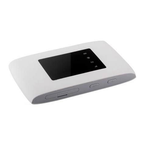
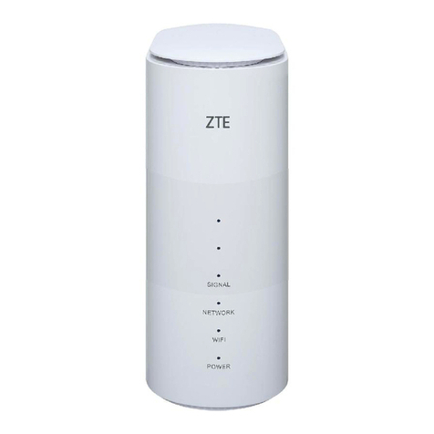
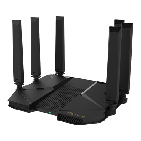
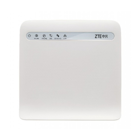
Zte R800 User manual

R800
HANDBOOK
I
LEGAL INFORMATION
By receiving the document from Shenzhen ZTEWelink Technology Co., Ltd (shortly referred to as ZTEWelink), you are deemed
to have agreed to the following terms. If you don’t agree to the following terms, please stop using the document.
Copyright © 2016 Shenzhen ZTEWelink Technology Co., Ltd. All rights reserved. The document contains ZTEWelink’s
proprietary information. Without the prior written permission of ZTEWelink, no entity or individual is allowed to reproduce, transfer,
distribute, use and disclose this document or any image, table, data or other information contained in this document.
ZTEWelink is a holding subsidiary of ZTE Corporation, dedicate to cellular M2M communication modules and M2M solutions.
& are the registered trademarks of ZTEWelink and ZTEWelink is granted to use ZTEWelink’s registered trademarks.
The name and logo of ZTEWelink are ZTEWelink’s trademark or registered trademarks. The other products or company names
mentioned in this document are the trademark or registered trademark of their respective owner. Without the prior written
permission of ZTEWelink or the third-party oblige, no entity or individual is allowed to use any company name, trademark, logo, label
or other information contained in this document.
The product meets the design requirements of environmental protection and personal security. The storage, use or disposal of
products should abide by the product manual, relevant contract or the laws and regulations of relevant country.
ZTEWelink reserves the right to make modifications on the product described in this document without prior notice, and keeps
the right to revise or retrieve the document any time.
If you have any question about the manual, please consult the company or its distributors promptly.
Copyright © ZTEWelink Technology Co., LTD, All rights reserved.

R800
HANDBOOK
II
SCOPE OF APPLICATION
Industry-grade Wireless Router
R800-U for North American
R800-J for Japan and Korea
R800-C for China
R800-F for China Private Network
R800-E for Europe
REVISION HISTORY
Version
Date
Description
V1.0
2016-12-10
First issue
ABOUT THIS DOCUMENT
Read This Before You Begin
Read the following symbols:
:Warning or caution
:Notes or description
CONTACT US
Address
Address: 2C, Tower D, Mindray Building, Gao-xin 12 Road South, Hi-tech Industrial Park, Nanshan District, Shenzhen, China
Website
www.ZTEWelink.com
Tel.
+86-755-26902600
E-mail
ZTEWelink@zte.com.cn
ZTEWelink provides a full range of professional technical support in all forms.

R800
HANDBOOK
III
CONTENTS
1. INTRODUCTION........................................................................................................................................................................................1
ABOUT THIS CHAPTER................................................................................................................................................................................... 1
1.1. OVERVIEW............................................................................................................................................................................................1
1.2. PRODUCT POSITIONING.......................................................................................................................................................................... 1
1.3. FUNCTIONS AND CHARACTERISTICS........................................................................................................................................................... 2
1.4. TECHNICAL INDICATORS AND SPECIFICATIONS............................................................................................................................................. 2
2. PRODUCT STRUCTURE............................................................................................................................................................................. 4
ABOUT THIS CHAPTER................................................................................................................................................................................... 4
2.1. HARDWARE STRUCTURE..........................................................................................................................................................................4
2.1.1. Device Appearance and Dimensions......................................................................................................................................... 4
2.1.2. Packing List................................................................................................................................................................................ 4
2.2. FUNCTIONAL BLOCK DIAGRAM.................................................................................................................................................................5
3. R800 LTE ROUTER INSTALLATION........................................................................................................................................................... 6
ABOUT THIS CHAPTER................................................................................................................................................................................... 6
3.1. UNPACKING.......................................................................................................................................................................................... 6
3.2. INSTALLATION AND CONNECTION............................................................................................................................................................. 6
3.2.1. SIM Card Installation................................................................................................................................................................. 6
3.2.2. Ethernet Cable Connection........................................................................................................................................................ 7
3.2.3. Serial Port Cable Connection..................................................................................................................................................... 7
3.3. POWER SUPPLY..................................................................................................................................................................................... 7
3.4. INSTALLATION CHECK............................................................................................................................................................................. 8
4. PRE-CONFIGURATION PREPARATION..................................................................................................................................................... 9
ABOUT THIS CHAPTER................................................................................................................................................................................... 9
4.1. STATUS OF INDICATOR LIGHT ON TERMINAL PANEL..................................................................................................................................... 9
4.2. LOCAL AREA CONNECTION CONFIGURATION...............................................................................................................................................9
5. ROUTER CONFIGURATION.....................................................................................................................................................................17
ABOUT THIS CHAPTER................................................................................................................................................................................. 17
5.1. OVERVIEW..........................................................................................................................................................................................17
5.2. BASIC CONFIGURATION.........................................................................................................................................................................17
5.2.1. Login to WEB Configuration Interface.....................................................................................................................................17
5.2.2. Network Configuration............................................................................................................................................................18
5.3. APPLICATION CONFIGURATION...............................................................................................................................................................27
5.3.1. Online Maintenance................................................................................................................................................................ 28
5.3.2. Network Management Configuration..................................................................................................................................... 30
5.3.3. DTU Configuration...................................................................................................................................................................31
5.3.4. DDNS Settings..........................................................................................................................................................................33
5.3.5. Traffic Statistics Settings......................................................................................................................................................... 37
5.3.6. QOS Settings............................................................................................................................................................................ 38
5.3.7. Timed Tasks Configuration...................................................................................................................................................... 39
R800
HANDBOOK
IV
5.4. VPN CONFIGURATION..........................................................................................................................................................................41
5.4.1. Overview..................................................................................................................................................................................43
5.4.2. VPDN Configuration................................................................................................................................................................ 43
5.4.3. N2N_V2 Configuration............................................................................................................................................................ 45
5.4.4. OPENVPN.................................................................................................................................................................................46
5.5. FORWARDING CONFIGURATION..............................................................................................................................................................51
5.5.1. Overview..................................................................................................................................................................................51
5.5.2. NAT.......................................................................................................................................................................................... 51
5.5.3. Route Configuration................................................................................................................................................................ 53
5.5.4. DMZ......................................................................................................................................................................................... 55
5.6. SECURITY CONFIGURATION....................................................................................................................................................................55
5.6.1. Overview..................................................................................................................................................................................55
5.6.2. Firewall.................................................................................................................................................................................... 55
5.6.3. IP Filtering................................................................................................................................................................................56
5.6.4. MAC Filtering........................................................................................................................................................................... 59
5.7. SYSTEM MANAGEMENT CONFIGURATION................................................................................................................................................ 61
5.7.1. Overview..................................................................................................................................................................................61
5.7.2. User Management...................................................................................................................................................................61
5.7.3. Configuration Management....................................................................................................................................................62
5.7.4. Firmware Upgrade.................................................................................................................................................................. 63
5.8. STATE................................................................................................................................................................................................ 73
5.8.1. Overview..................................................................................................................................................................................73
5.8.2. Basic Information.................................................................................................................................................................... 73
5.8.3. LAN State.................................................................................................................................................................................74
5.8.4. WAN State............................................................................................................................................................................... 75
5.8.5. WLAN.......................................................................................................................................................................................76
5.8.6. Mobile Network State............................................................................................................................................................. 77
5.9. RESET BUTTON.................................................................................................................................................................................. 78
6. TYPICAL APPLICATIONS......................................................................................................................................................................... 79
ABOUT THIS CHAPTER................................................................................................................................................................................. 79
6.1. OVERVIEW..........................................................................................................................................................................................79
6.2. TASK MANAGEMENT APPLICATION......................................................................................................................................................... 79
6.3. DTU FUNCTIONAL APPLICATION............................................................................................................................................................ 80

R800
HANDBOOK
1
1. INTRODUCTION
About This Chapter
Sections
Description
1.1 Overview
This section briefly describes R800 LTE Router, so that you can have a basic understanding of the
product.
1.2 Product Positioning
This section describes the product positioning of R800 LTE Router.
1.3 Functions and characteristics
This section describes the functions and characteristics of R800 LTE Router.
1.4 Technical Indicators and Specifications
This section describes the technical indicators and specifications of R800 LTE Router.
1.1. Overview
R800 LTE Router supports such 4G network architectures as TDD LTE and FDD LTE, and such 3G+ network architectures as
HSPA+, and such 3G network architectures as TD-SCDMA, EVDO and WCDMA. It has downward compatibility with such 2G network
architectures as GPRS\CDMA. It connects 2G/3G/3G+/4G LTE network with wireless linking technology and provides you with
high-speed wireless network bandwidth. R800 LTE Router adopts high-performance 32-bit MIPS processor and is based on common
basic platform, with industry-grade built-in wireless 3G/3G+/4G LTE module. The router is provided with an embedded operating
system, and, since wireless network is unstable with great delay variations, and has other features, we conduct optimization design,
for the purpose of providing you with high-speed and reliable router and data transmission functions.
R800 LTE Router supports more than two Ethernet interfaces, which can better satisfy the need of such applications for more
than one LANs as self-service terminal, charging pile, advertising machine and IPC. R800 LTE Router has built-in firewall and supports
IP, domain name and MAC white list and blacklist filtering; besides, it supports access control list, which can effectively control
unauthorized access by external users.
R800 LTE Router supports Wi-Fi 802.11b/g/n, with the speed up to 150Mbps, which enables easy construction of wireless LAN;
it supports WEP/WPA/WPA2 and other ways of encryption, which can guarantee the security of wireless LAN.
1.2. Product Positioning
Vlink data communication products are widely applied in tens of industries in China and in more than 50 countries and regions
across the globe. R800 LTE Router is applied in many sectors, including telecommunication, finance, information media, power,
transportation, energy, environmental protection, meteorology, water conservancy, heating power, gas, petroleum and
petrochemical industry, oil field, coal mine, and so on.
Finance
With regard to its application in the financial industry, R800 LTE Router provides highly-secured financial data transmission
through IPSec VPN etc. Besides, 3G/4G wireless mobile application greatly improves the speed of network layout and ease of use.
See Figure 1-2-1 for typical networking.
Figure 1-2-1 Diagram of Application in Financial Industry
Information Media
R800 LTE Router can be connected with coupon printer, subway ticket machine, self-service terminal and the like. Based on
3G/4G wireless communication, it can make sure that terminals distributed at different positions can be connected in a centralized
manner, so as to realize communication with the server. See Figure 1-2-2 for typical networking.

R800
HANDBOOK
2
Figure 1-2-2 Diagram of Application in Information Media Industry
Security Access Communication
R800 LTE Router supports transmission of videos and pictures, and can be connected with the access monitoring device at the
security access. Based on 3G/4G wireless communication, R800 LTE Router transmits the picture taken by the monitoring device to
the designated server, so as to easily realize transmission of monitoring data of different road sections. See Figure 1-2-3 for typical
networking.
Figure 1-2-3 Security Access Communication Application
1.3. Functions and Characteristics
Basic functions
The built-in 2G/3G/4G LTE modules support WCDMA, EVDO, TD-SCDMA, HSPA+, TDD LTE and FDD LTE, respectively, and
has downward compatibility with CDMA1x and EDGE/GPRS.
Support VPDN and APN private network access
Support DHCP Server
Support serial port DTU function
Support local, remote and platform firmware upgrade
Support WEB, Web Master and many other parameters management methods
Support M2M platform management; it is possible to conduct real-time statistics of device traffic and monitor the
network state of the device
Support settings import and export
Support DNS Proxy and DDNS
Support NTP network timing
Support timing management, and enable effective control over online traffic and duration
Support link detection functions (such as online stay), and ensure stable and reliable wireless network
Third-party EMC testing report, environment reliability test
1.4. Technical Indicators and Specifications
Supportable network
FDD LTE/TDD LTE
EVDO
WCDMA (HSDPA,HSUPA,HSPA+)
TD-SCDMA
EDGE/GPRS

R800
HANDBOOK
3
CDMA 1x
Network standard
IEEE 802.11n
IEEE 802.3
IEEE 802.3u
Device interface
3G/3G+/4G LTE antenna interface: SMA-K (inner nut needle)
Wi-Fi antenna interface: SMA-K (SMA inner nut needle)
Module: built-in 2G/3G/4G LTE module (upgradable and replaceable)
Ethernet interface: 1x10/100Mb LAN port/1x10/100Mb LAN/WAN port
Console interface: RS232/RS485 (optional)
RESET interface: one-key recovery to factory settings
SIM/USIM interface: self-popup drawer-type SIM card seat
Power supply
Service voltage: +12V DC/1A
Other parameters
Product dimensions (L×W×H): 118 mm x100 mm x 22mm
Weight: 357g
Working temperature: -30~+75ºC
Storage temperature: -40~+85ºC
RH: <95% (no condensation)

R800
HANDBOOK
4
2. PRODUCT STRUCTURE
About this Chapter
Sections
Description
2.1 Hardware Structure
This section briefly describes the hardware structure of R800 LTE Router.
2.2 Functional Block Diagram
This section describes the functional block diagram of R800 LTE Router.
2.1. Hardware Structure
2.1.1. DEVICE APPEARANCE AND DIMENSIONS
External View
See Figure 2-1-1 for the physical appearance of Vlink R800 LTE Router.
Figure 2-1-1 Physical Appearance of R800 LTE Router
Table 2-1-1 Device Dimensions of R800 LTE Router
Name of Device
L×W×H(mm)
Socket Description
R800 LTE Router
118×100×22
Two LAN ports: To connect lower computer (you can select one WAN port: To connect lower computer)
One Console (customized RJ45 serial port is optional; support RS232/RS485)
2.1.2. PACKING LIST
R800 LTE Router has the following accessories, see Table 2-1-2.
Table 2-1-2 R800 LTE Router Accessories List (Standard)
Name of Accessory
Quantity
Remark
R800 LTE Router Main Machine
1
3G/4G Antenna
2 pieces
Installation Hardware
1 pair
Handbook
1
12VDC Power Adapter
1
WLAN Antenna
1 pieces
Packed as per customer order configurations
RJ45 Cable
1 piece
Packed as per customer order configurations

R800
HANDBOOK
5
2.2. Functional Block Diagram
See Figure 2-1-2 for the functional structure of R800 LTE Router.
Figure 2-1-2 Functional Block Diagram of R800 LTE Route
CPU (CPU, SRAM, FLASH) core processing unit
Serve the following major functions:
Control 3G/4G module dial-up and off-line
IP data forwarding
Operate routing protocol, firewall protocol, VPN protocol and other advanced function
Maintain normal operation of the device
Control the device parameter configuration
Serial port (UART data processing module
The serial port of R800 LTE Router mainly serves to transmit data between the router and the serial port device.
LAN/WAN port data processing module
When the LAN/WAN port of the router is used as LAN port, the data processing module communicates with the lower
computer through RJ45 cable and enables the lower computer to serve the function of IP data forwarding.
When the LAN/WAN port of the router is used as WAN port, the data processing module connects with Internet by way of
cable and enables data transmission in public network.
Ethernet port data processing module
The Ethernet port data processing module of the router communicates with the lower computer through RJ45 cable and
enables the lower computer to serve the function of IP data forwarding.
3G/4G module
This module mainly serves 3G/4G networking function, so as to enable IP data forwarding by the terminal product.

R800
HANDBOOK
6
3. R800 LTE ROUTER INSTALLATION
About this Chapter
Sections
Description
3.1 Unpacking
This section describes R800 LTE Router unpacking and the packing list check.
3.2 Installation and Connection
This section describes the installation of SIM card of R800 LTE Router and its connection with Ethernet port and
serial port cable, etc.
3.3 Power Supply
This section describes the requirement and method of power supply for R800 LTE Router.
3.4 Installation and Inspection
This section describes how to conduct post-installation check of R800 LTE Router.
3.1. Unpacking
When the device arrives at the site, it shall be unpacked and inspected for integrity of accessories. In normal case, the
complete device shall have the accessories listed in Table 2-2. Unpack it and well store the packing materials for secondary
transshipment.
3.2. Installation and Connection
3.2.1. SIM CARD INSTALLATION
While installing SIM card, please make sure the router is in power-off condition, so as not to burn the SIM card.
Step 1 Press slightly on the button on SIM card seat with something sharp to make the seat pop up, and take out the seat.
See Figure 3-2-1.
Figure 3-2-1 SIM Card Seat Popup
Step 2 Make side up the metal face of SIM card, and insert it into the card seat, with the unfilled corner outward. Then,
push the card seat into the slot. See Figure 3-2-2.
Figure 3-2-2 SIM Card Installation Diagram
Step 3 lock SIM card cover to prevent card steal. See Figure 3-2-3.

R800
HANDBOOK
7
Figure 3-2-3 SIM Lock SIM card cover
3.2.2. ETHERNET CABLE CONNECTION
R800 LTE Router has simple configuration and is easy to use. Once it is connected through RJ45 cable, normal configuration
management and data communication can be realized. R800 LTE Router can not only be directly connected with the lower computer,
but also be connected through switchboard. See Figure 3-2-4 and Figure 3-2-5.
Figure 3-2-4 Direct Cable Connection
Figure 3-2-5 Ethernet Connection with Multiple Devices
3.2.3. SERIAL PORT CABLE CONNECTION
R800 LTE Router supports serial port DTU function. When you need to use this function, connect your device with RJ45 by ways
of the serial port.
3.3. Power Supply
R800 LTE Router can be applied in complicated conditions, and the power supply can be 12V DC.

R800
HANDBOOK
8
3.4. Installation Check
Before the installed router is energized, try pressing SIM card to check whether it is tight. Energize and check the working
condition of the router; at this moment, the PWR indicator light is on; the LAN port will light up the moment the router is energized;
some time later, SYS light is on, indicating that the system has been started and begun to work normally.
Operation steps
Step 1 Check whether the antenna connection is correct.
Step 2 Check whether SIM card is installed in a correct manner, and confirm whether it is valid.
Step 3 Supply power to R800 LTE Router.
If the light of the LAN port connected with the lower computer is on when R800 LTE Router is energized, it means the
Router has normal power supply.
Supply power for some time, and then SYS indicator light of the router is on, it means the router system has been started.
After SYS indicator light is on for some time, NET indicator light is on and quick-flashing, it means the router has found the
module and starts dial-up.
In the process of dial-up by the router, PPP(NET) light is on.
At the end of dial-up by the router, PPP(NET) light is always on, it means the dialed network is 3G/4G; if it is slow-flashing,
it means the dialed network is 2G/2.5G/2.75G.
For different modules, the time that the router takes to find the module is different. The dial-up time also
differs for network disconnection. Therefore, the time that the router takes to dial up and obtain IP address is different
for different modules, but the router dial-up process is in strict accordance with the aforesaid steps.

R800
HANDBOOK
9
4. PRE-CONFIGURATION PREPARATION
About this Chapter
Sections
Description
4.1 Status of Indicator Light of Terminal Panel
This section briefly describes the status of terminal panel indicator lights of R800 LTE Router.
4.2 Local Area Connection Configuration
This section describes the process of configuring local area connection for R800 LTE Router
installed.
4.1. Status of Indicator Light on Terminal Panel
There are eight LED indicator lights on the front panel of R800 LTE Router, indicating the working condition and network
condition of R800 LTE Router. See Table 4-1-1 for indicator light status description.
Table 4-1-1 Indicator Light Description
Name of Indicator Light
Status Description
PWR
Light on: the router has normal power supply
Light off: the power supply is unsatisfactory/ power off
LAN(1,2)
Light always on: the Ethernet port is in normal connection with other devices through the cable.
Light flash: the Ethernet port has data reception and transmission
Light off: the Ethernet cable is disconnected or connected with other device in an abnormal manner
SYS
Light always on: the system starts and works in normal condition.
Light off: the system is not fully started (within 10 minutes after energized or in the re-start process)
Light flash: the device has an abnormal body temperature
PPP(Online)
Light always on: successful dial-up enables access to 3G/4G network
Slow flash (0.5s flash): successful dial-up enables access to 2.5G network
Quick flash (2s flashes): in the dial-up process
Light off: it is failure to find the module or dial-up disabled
VPN
Light on: any VPN connected
Light flash: connecting
Light off: disconnect
SIG
Light on: Signal 21~31
Slow flash: Signal 11~20
Quick flash: Signal1~10
Light off: no signal
BAK
Light on: WAN main link and LTE are working
Light flash: abnormal and disconnected
Light off: WAN is working, while LTE is not working
4.2. Local Area Connection Configuration
Prerequisites
R800 LTE Router has been energized.
LAN Ethernet port of R800 LTE Router has been connected through Ethernet cable.
See “3.2.2 Ethernet Cable Connection”for specific operation. The local area connection of R800 LTE Router has two ways:
specified IP and obtaining an IP address automatically by using DHCP. The two ways will be described in detail.
Specified IP
Step 1: Click “Start>Control Panel”, and double click on “Network Connection”in the open window. See Figure 4-2-1.

R800
HANDBOOK
10
Figure 4-2-1 Network Connection Window
Step 2: Double click on “Local Area Connection”, and open the window “Local Area Connection Status”. See Figure 4-2-2.
Figure 4-2-2 Local Area Connection Status
Step 3: In the window “Local Area Connection Status”, click “Attributes”to open the window “Local Area Connection
Attributes”.

R800
HANDBOOK
11
Figure 4-2-3 Internet Protocol(TCP/IP)
The latter configuration can be done in two ways, i.e. general configuration and advanced configuration.
General configuration
1. In the window “Local Area Connection Attributes”, double click on “Internet Protocol (TCP/IP)”, and open the window
“Internet Protocol (TCP/IP) Attributes”. Revise the general network configuration in the option “General”. See Figure 4-2-4.
Figure 4-2-4 General Network Configuration
Among factory default parameters of R800 LTE Router,
IP address: 192.168.1.1
Subnet Mask: 255.255.255.0
Therefore, in the window “Internet Protocol (TCP/IP) Attributes”, the configuration of “Default Gateway”and “Subnet
Mask”is R800 LTE Router factory default settings.
IP address can be 192.168.1.* (* refers to any integer from 2~254).

R800
HANDBOOK
12
2. Click “OK”, done.
Advanced configuration
This method is based on the existing network environment configuration (Step 1~Step 3); where it is not desired to disconnect
LAN communication of PC and it is desired to have R800 LTE Router configured, a router can be additionally provided.
1. In Figure 4-4, click “Advanced”to open “Advanced TCP/IP Setting”. See Figure 4-2-5.
Figure 4-2-5 Advanced TCP/IP Setting
2. Click “Add”in “IP Address”, and fill out the IP address you want to configure. See Figure 4-2-6.
Figure 4-2-6 TCP/IP 地址
3. Click “Add”, done.
Obtaining an IP address automatically by using DHCP
DHCP server built in R8004G Router automatically allocates IP address to the connected terminals (or PC, etc.) according to the
preset parameters, which saves the process of manual allocation of IP address to terminals. Therefore, the router connection can be
realized in the principle of DHCP server.
6DHCP service built in R800 LTE Router is open when delivery.
Step 1: Click “Start>Control Panel”, and double click on “Network Connection”in the open window. See Figure 4-2-7.

R800
HANDBOOK
13
Figure 4-2-7 Network Connection Window
Step 2: Right click on “Local Area Connection 2”, and click “Attributes”in the popup menu; open the window “Local Area
Connection 2”. See Figure 4-2-8.
Figure 4-2-8 Local Area Connection Attributes
Step 3: In the window “The Connection Uses the Following Item (O)”, click “Internet Protocol (TCP/IP)”, and double click to
open the window “Internet Protocol (TCP/IP) Attributes”. See Figure 4-2-9.

R800
HANDBOOK
14
Figure 4-2-9 Internet (TCP/IP) Attributes
Step 4: If“Internet Protocol (TCP/IP) Attributes”is as Figure 4-2-9 shows, then no alteration is required; if not, select“Obtain
an IP Address Automatically”in “General”.
In the window “The Connection Uses the Following Item (O)”, click “Internet Protocol (TCP/IP)”, and double click to open
the window “Internet Protocol (TCP/IP) Attributes”. See Figure 4-2-9.
Step 5 Click “OK”, done.
Configuration Check
Step 6: Click “Start>Running”, insert “cmd”in “Running”and press “Enter”. Open the window “Running”. See
Figure 4-2-10.

R800
HANDBOOK
15
Figure 4-2-10 “Running”Window
Step 7: Insert the command “ipconfig”in the “Running”window. For the above two connection configuration methods,
the IP address showed in the “ipconfig”window is different: for the former, IP address is the IP address you insert in Figure 4-2-4;
see Figure 4-2-11; for the latter, IP address is the random numbers from “2~254”; see Figure 4-2-12. If the information showed in
the window is as Figure 4-2-12, it means that IP configuration is normal.
Figure 4-2-11 “ipconfig”Execution Result of Specified IP (General Configuration)
Other manuals for R800
1
Table of contents
Other Zte Network Router manuals
Popular Network Router manuals by other brands

ZyXEL Communications
ZyXEL Communications PLA5256 quick start guide

Allied Telesis
Allied Telesis AT-WR4662n Quick installation guide

ZyXEL Communications
ZyXEL Communications ES-2108 Declaration of conformity

Asus
Asus RT-AC55UHP quick start guide

GigaComm
GigaComm NetComm Wi-Fi Set-up Guide

Huawei
Huawei RRU3808 installation guide