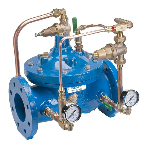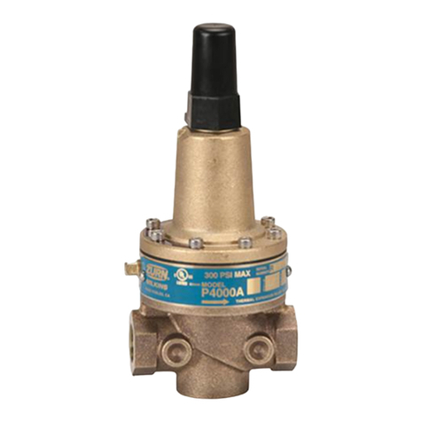
Troubleshooting
PILOT SYSTEM FUNCTION CHECK
CAUTION: To prevent personnel injury and damage to
equipment check that downstream venting is adequate
prior to start-up and test procedures.
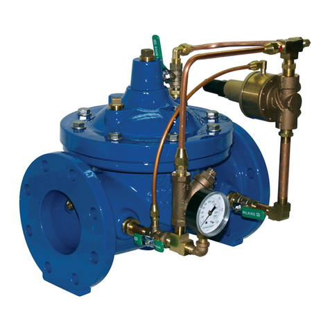
SURGE PROTECTION PILOT CHECK
1.Withwaterowingthroughthemainvalveturnthesurgepro-
tectionpilot(PV-RLF)adjustmentscrewclockwiseallthewayin.
2.Whileowingcloseandopenthecoverisolationballvalve
on the surge protection pilot while watching downstream
pressure. If downstream pressure changes when opening
and closing the cover isolation ball valve the pilot valve is not
sealingproperly.Itisrecommendedthatthepilotvalvebe
disassembled and inspected.
3. Close the outlet isolation ball valve on the pressure reduc-
ing pilot. The main valve should close, after sometime. If
installed,verifythevalvepositionindicator(modelZPI)is
closed.
4.Ifthereiscontinuousowfromtheoutletofthemainvalve,
themainvalveisnotsealingproperly.Itisrecommended
thatthemainvalvebedisassembledandinspected(Referto
“Disassembly”section).
5.Opentheoutletisolationballvalveonthepressurereduc-
ing pilot. The outlet pressure must be lower than the inlet
pressureandwatermustbeowingthroughthemainvalve
for the next steps 6-7.
6. Close all three isolation ball valves connected to the pres-
surereducingpilot.Closethecoverisolationvalverst,then
the other two valves.
7. With all three surge protection isolation ball valves open,
slowlyturnthesurgeprotectionadjustmentscrewcounter-
clockwise until the outlet pressure starts to drop.
8. If the downstream pressure does not start to drop, the pilot
valveisnotopeningproperly.Itisrecommendedthatthe
surge pilot valve be disassembled and inspected.
PRESSURE PILOT REDUCING CHECK
1. With pressure on the inlet of the ZW209Q close the 3 iso-
lation ball valves connecting to the surge protection pilot.
2.Whileowingwaterslowlyclosetheoutletballvalveinthe
pressurereducingpilotsystem.Allowthecovertopressurize
andthemainvalvetoclose.Ifinstalled,verifythevalveposition
indicator(modelZPI)isinaclosedposition.
3. Close the cover ball valve to keep the main valve closed.
4.Proceedwithventingoutletdownstreampressurebyopen-
ing a source downstream. When opening the downstream
sourceifthereiscontinuousow,themainvalveisnotsealing
properly.Itisrecommendedthatthemainvalvebedisassem-
bledandinspected(Referto“Disassembly”section).
5. With the main valve closed, open outlet isolation valve
andallowasmallamountofwatertoowthroughthepilot
valvebycrackingopenadownstreamtting.Thereshouldbe
continuousow.Ifnot,thepressurereducingpilotvalveisnot
openingproperly.Itisrecommendedthatthepilotvalvebe
disassembledandinspected(Refertoappropriatepressure
reducingpilotvalveinstructionsheet).
6. Monitor outlet pressure while cracking open and closing the
downstreamshutoffvalveandcomparetothedesiredsystem
settings. If the outlet pressure is the same as the inlet pres-
sureorclimbsmorethan15psiabovetheowingreduced
pressuresetpoint,thepressurereducingpilotisnotproperly
regulating(refertothepilottroubleshootingPressureReduc-
ingPilotSystemTroubleshooting,Table2.CorrectiveAction
section).
7.Ifthepressureisregulatingtothedesiredsystempres-
sures proceed with diagnosis checks for the main valve.
DIAGNOSIS CHECKS
CAUTION: Do not service valve while under pressure.
When performing diagnosis checks on the ZW209Q when
the valve is fully open, high ow rates and high down-
stream pressures can occur.
DIAPHRAGM CHECK
1.Slowlycloseupstreamshutoffvalveandrelieveallpressure
downstream.
2. With all pressure relieved in the main valve, close both inlet
and outlet isolation valves and remove side plug on cover and
leave off.
3.Thenopenupstreamshutoffvalvepartially,allowingwater
toowthroughthevalve.Whileowingwatermonitortheopen-
ingonthecover.Ifuidbeginstoowoutoftheopenholein
thecover,thenthereismostlikelydamagetothediaphragm
oruidisleakingpastthediaphragmassemblyduetoloose
assembly.Itisrecommendedthatthevalvecoverberemoved
toinvestigatetheleakage(Toremovecoversee“Maintenance”
sectionforprocedures).Ifnowaterowsoutofcoverthenthe
diaphragmisgoodandyoumayproceedtothediaphragm
movement check.
DIAPHRAGM MOVEMENT CHECK
1. The diaphragm movement check can be determined during
the diaphragm check or it can also be performed with the use of
a valve position indicator model ZPI.
2. Replace cover plug and open pilot ball valves on inlet and cover.
3.Closingtheoutletisolationballvalveswilldirecttheowto
the cover causing it to close. NOTE: Slow or delayed closing
of main valve is normal and is due to the time requirements
to ll, pressurize cover, and stretch the diaphragm into the
closed position. This normal delay is not mechanical bind-
ing of the valve assembly.
4. Using the valve position indicator, make note of the closed
position on the indicator. Compare distance of the open mark to
the close mark and compare to Table 3.
5.Verifythatthemainvalveisclosed,byopeningadown-
streamsource(nottheoutletisolationballvalveonthemain
body).Ifwatercontinuouslyows,thenthemainvalveisnot
sealingproperly.Doublecheckthevalvemovementmatches
thevaluesinTable3andrefertothedisassemblyprocedures
section if it does not. This is an indication that the main valve is
not sealing due to an obstruction between the seat and the seal
oradamagedseal.Ifwaterdoesstopowingandthemeasured
valve movement does not match Table 3, then there is possible
damageunderthecover.Removecovertoidentifyobstruction
andreplacepartsasnecessary.
TABLE 3. VALVE STEM TRAVEL
VALVE SIZE
(in)
VALVE SIZE
(mm)
STEM TRAVEL
(in)
STEM TRAVEL
(mm)
1-1/4" - 1-1/2" 38 0.4 10.2
2" 50 0.7 18.0
2-1/2" 65 0.8 21.3
3" 80 0.9 23.4
4" 100 1.1 28.8
6" 150 1.7 43.4
8" 200 2.4 59.7
10" 250 2.8 71.1
12" 300 3.4 86.4
14" 350 3.8 96.5
16" 400 4.3 109.2


