Maintenance Instructions
7. For smaller valves (6” and below) diaphragm checks can
beperformedbyhandwiththeuseofavalvestemtool.The
valve stem tool can be made using Table 4 to create a “T” bar
handle with the appropriate threads on the opposite end of the
“T” handle.
8. To perform the diaphragm check using the vale stem tool,
rstremoveallpressureinthesystemandventthecover.Then
remove the center plug on the cover and insert tool into the top
ofthestemthreads.Oncethetoolisinserted,thevalvecanbe
liftedupandthevalvemovementcanbemeasuredbycreating
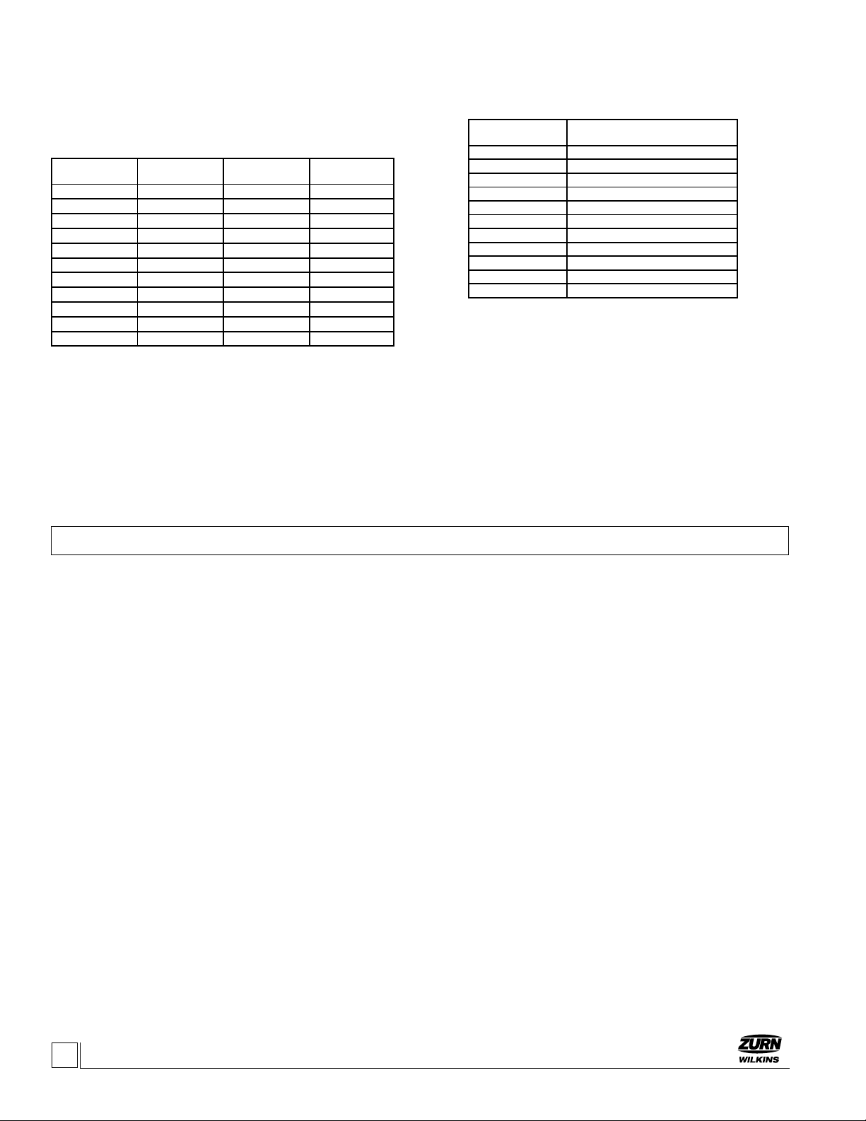
TABLE 4. VALVE STEM THREAD SIZE
SEAL CHECK
1. To check the seal of the valve disc, an additional pressure
gauge will be needed downstream of main valve.
2.Withthevalveowingslowlyclosepilotoutletballvalvesto
applypressuretocoverandallowtoclose.Ifthesolenoidop-
tionis“NormallyClosed”thesolenoidwillhavetobeenergized
toopenandallowowtocover.
3. Monitor the pressure on the inlet and installed outlet gauge.
The pressure on the outlet side should be zero. If the pressure
matches inlet pressure, the main valve is leaking or the outlet
ballvalveonthepilotsystemisallowingpressuretocreepby.
Eitherwayitisrecommendedthatthevalvebedisassembled
andinspected(referto“Disassembly”section).
PREVENTATIVE MAINTENANCE
The Zurn Wilkins ZW200 Models requires minimal mainte-
nance.However,itishighlyrecommendedtoscheduleannual
inspectionsandtohavearepairkitbeforedisassembly work
begins.
Disassembly
Warning: With the ability to perform inspections. And
maintenance without removal from the system, it is very
important that all shut off valves be closed and all pres-
sure relieved in the valve before beginning disassembly.
Failure to do so can result in personnel injury or equip-
ment damage.
1.Verifythatallpressuresourcesareclosed,upanddown-
stream of valve.
2.Removepressureinpilotsystembylooseningthetubet-
tingstothevalvebodyandcover.Whenallpressurehasbeen
vented, continue to disassemble the pilot control valve and
covertubing.NOTE:Takingapicturebeforeteardowncanhelp
withre-assemblyofpilotsystem.
3.Nextremovethecoverbylooseningandremovingthecover
bolts.Ifthecoverdoesnotcomeoffeasilyitmaybenecessary
to loosen the cover using a brass chisel and rubber mallet. Ap-
plythechiselunderthecoverpointingupwardawayfromvalve
bodyandtapbottomofcoverwiththechiselandmalletto
loosenthecover.Oncethecoverisloose,pullcoverstraightup
to avoid damaging the stem and stem bearing in the cover.
4.Withthecoverremoved,thediaphragmassemblycanbere-
moved. To avoid damaging the seat bushing, grab the stem and
lift straight up. For larger valves 8” and up it is recommended that
aneyeboltwiththeproperstemthreadsbeusedwithahoist
tolifttheassemblyoutofthevalve(seeTable3forappropriate
stem threads).
5.Nextitisrecommendedthatthediaphragmassemblybe
placedinavisewiththebottomhexnutsecured.Oncesecured
remove the spring and stem nut. While removing the nut in-
spect the stem threads. Clean stem with a wire brush if mineral
deposits or corrosion are present.
6. After inspecting the stem and removing the nut the dia-
phragmassemblycanbedismantled.Ifthevalvehasnotbeen
servicedinawhileitispossiblethattheassemblywillrequire
theuseofarubbermalletorprybarstodismantletheassem-
bly.Ifthisisthecasegentlytaporprythecomponentsuntilthe
components are free to move. When disassembling be sure to
clean,inspect,andsaveallcomponents.Replaceanydamaged
componentsasnecessary.
7. The last component to inspect is the seat which is in the
bodyofthemainvalve.Duringinspectionoftheseat,cleanand
polishasnecessarywithnegritwet/drysandpaper(400grit
orhigher).Typically,aftercleaningthereisnovisualdamageor
excessive wear the seat should not require removal. If damage
ispresentortheseatisexcessivelyworntheseatshouldbe
replaced.
8. To remove the seat, on valves 6” and smaller the seat is
threadedintothebodyandwillrequireaseatremovaltool.
Care should be taken when removing the seat to avoid damaging.
INSPECTION OF COMPONENTS
Cleaningofcomponentsisrequiredforproperinspection.Lime
depositsarecommoninsystemsthatusewater.Toremove
is not sealing due to an obstruction between the seat and the
sealoradamagedseal.Ifwaterdoesstopowingandthe
measured valve movement does not match Table 3, then there
ispossibledamageunderthecover.Removecovertoidentify
obstructionandreplacepartsasnecessary.
4ZURN WILKINS
1747CommerceWay,PasoRobles,CA93446Phone:855-663-9876Fax:805-238-5766
www.zurn.com
TABLE 3. VALVE STEM TRAVEL
VALVESIZE
(in)
VALVESIZE
(mm)
STEMTRAVEL
(in)
STEMTRAVEL
(mm)
1-1/4"-1-1/2" 38 0.4 10.2
2" 50 0.7 18.0
2-1/2" 65 0.8 21.3
3" 80 0.9 23.4
4" 100 1.1 28.8
6" 150 1.7 43.4
8" 200 2.4 59.7
10" 250 2.8 71.1
12" 300 3.4 86.4
14" 350 3.8 96.5
16" 400 4.3 109.2
marks on the tool in the opened and closed positions. Replace
orrepairanypartsasnecessary.
VALVESIZE(in) THREADSIZEUNFINTERNAL
1-1/4"-1-1/2" 10-32
2" 10-32
2-1/2" 10-32
3" 1/4-20
4" 1/4-20
6" 1/4-20
8" 3/8-16
10" 3/8-16
12" 3/8-16
14" 3/8-16
16" 3/8-16