manuals.online logo
Brands
  1. Home
  2. •
  3. Brands
  4. •
  5. Zurn Wilkins
  6. •
  7. Control Unit
  8. •
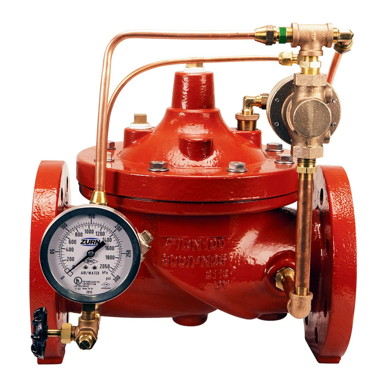
  9. Zurn Wilkins ZW215FP Installation manual

Zurn Wilkins ZW215FP Installation manual

1
INSTALLATION
NOTE: Prior to installation of the ZW215FP, ensure that all debris
is ushed out the piping system before installed.
1. During the installation of a ZW215FP in a sprinkler system, verify
installation meets requirements of local law or the Authority Having
Jurisdiction.
2. Allow for adequate space around the valve for making adjust-
ments and servicing.
3. PositiontheZW215FPinlinematchingthedirectionofowas
indicatedonthevalvemodeltagwiththeproperdirectionofowin
the system. The valve must be installed on the discharge side of the
repump.
4. Connect pilot control sensing connection to the suction side of
the pump by minimum 3/8 in diameter tubing.
5. Once control valve and sensing line are installed, double check
all fasteners/bolts in the pilot system and on main valve are tight and
there is no damage prior to pressurizing system.
NOTE: Pressure in some applications can be very high so be
thorough in checking and inspecting for proper installation and
makeup.
6. Zurn Wilkins valves are designed to operate in both the vertical
and horizontal positions. However, it is recommended that ZW215FP’s
6” and larger, be installation in the horizontal position. The horizontal
positioning of the larger valves avoids premature wear due to mass of
plunger assemblies as well as allows for greater accessibility during
annual inspections, and maintenance.
START-UP
CAUTION: To prevent personnel injury and damage to equip-
ment check that downstream venting is adequate prior to
start-up and test procedures. All adjustments under pressure
should be made slowly. If the main valve opens or closes too fast
it may cause surging in upstream piping.
Installation  Start-up  Maintenance Instructions
Model ZW215FP
Fire Pump Suction Control Valve
Globe and Angle Pattern Bodies
2", 2-1/2", 3", 4", 6", 8", & 10"
ZW215FP
Class 150 Flanged
Max 250 psi Inlet
ZW215FPG
Grooved
Max 300 psi Inlet
ZW215FPY
Class 300 Flanged
Max 300 psi Inlet
1. Pressurize the upstream side of the ZW215FP.
2. Asthevalveisllingwithwater,itisnecessarytobleedthemain
valve and pilot system of air. To vent air, partially open or loosen the
highestplugsorttingsinthesystem.TheZPIvalvepositionindicator
is a great location, as it has a test cock at the top to vent air pressure.
It may be necessary to bleed system more than once. After removal of
airinthesystemtightenallloosettings.NOTE: If valve is installed
vertically, it will be necessary to loosen some upper cover bolts
until you have vented all the air from the cover chamber.
3. Install a pressure gauge on the suction side of the pump or install
a gauge in the test cock on the sensing line to read the suction pres-
sure.
4. Loosen the pilot adjustment screw until the adjustment screw
can be turned by hand. Note: A small amount of spring force must
be maintained so the spring and spring discs do not fall out of
alignment. Do not loosen the pilot adjustment screw completely.
Note: The control valve should open and allow a lot of water to
ow. If there is no ow, continue turning the pilot adjustment screw
counterclockwise.Oncewaterisowingthroughthecontrolvalveit
is necessary to lower the suction pressure below the desire set pres-
sure. One can cause the suction pressure to decrease by increasing
owthroughthepumporusingavalveupstreamofthepumpsuction
to throttle water to the pump.
5. Once suction pressure is below desired minimum suction pres-
sure, slowly turn the pilot valve adjustment screw clockwise. As the
screw is tightened the control valve will slowly start to close causing
upstream pressure to increase. Continue turning adjustment screw
clockwise until suction pressure is stable at the desired set pressure.
6. Tighten adjustment screw jam nut once step 4 is completed. To
verify proper operation of the ZW215FP, view the valve during normal
operation and check the valve for minimum suction pressure setting.
Adjustments can be made at anytime.
Installation / Start-up
DESCRIPTION
The Zurn Wilkins Model ZW215FP Fire Pump Suction Control Valve
isdesignedspecicallyforFireSuppressionSystemstopreventre
pumps from over-drawing from the water supply resulting in damage
to the pump or the supply network because of very low or negative
pressuresonthesuctionsideoftherepump.Thepilotassembly
reacts quickly to increases and decreases of suction pressure.
The control valve will close if suction pressure drops below the set
pressure. The control valve will open again once suction pressure
rises to the control valve set pressure and will modulate to keep
the suction pressure at the set pressure until supply increases. In
addition the Model ZW215FP comes standard with red epoxy coat-
ing internally and externally for corrosion protection, as well as a
test cock on the sensing port for quick bleeding of sensing line. The
ZW215FP is available in both globe and angle pattern bodies.
ZW215FPTH
Threaded
Max 300 psi Inlet
®
ZURN WILKINS
1747 Commerce Way, Paso Robles, CA 93446 Phone:855-663-9876 Fax:805-238-5766
®
www.zurn.com
FM
APPROVED
!WARNING: Cancer and Reproductive Harm - www.P65Warnings.ca.gov
!ADVERTENCIA: Cáncer y daño reproductivo - www.P65Warnings.ca.gov
!AVERTISSEMENT: Cancer et néfastes sur la reproduction - www.P65Warnings.ca.gov
2
ZW215FPC SCHEMATIC
STANDARD COMPONENTS
1. Main Valve
2. SXL "Wye"
3. Restriction Tube Fitting
4. PV-RLF Pressure Relief Valve
5. ZPI Visual Position Indicator
The Zurn Wilkins ZW215FP utilizes a pressure relief pilot valve that installs on the discharge side of the control circuitry. The pilot
Model PV-RLF is a direct acting, normally closed, spring loaded, diaphragm actuated valve. The operation of the ZW215FP begins
withaccuratelysizingthevalve,thennetuningthecontrolcircuitrybyadjustingthePV-RLFtoopenatthedesiredsuctionpres-
sure. A sensing line runs externally from the suction side of the pump to the pilot control chamber under the diaphragm. Thus,
suction pressure exceeding the preset of the pilot acts to open the pilot valve while the adjustable spring in the pilot seeks to keep
it closed. The result is a modulating action in the pilot that is transmitted to the cover of the main valve. This creates a mirror modu-
lationofthediaphragmassemblyinthemainvalve.Suctionpressureismaintainedwithinnarrowlimitsregardlessofchangingow
rates or outlet pressure when supply has decreased below acceptable limits.
Drip Tight Closing Operation
With the use of a three way pilot control, inlet
pressure is directed to the cover where the
pressure forces the valve closed.
Full Open Operation
Using a three way pilot control, pressure is
vented to the outlet from the cover chamber
which enables the inlet pressure to open the
main valve.
Modulating Action
Utilizing a Wilkins modulating control sys-
tem, pressure changes to the cover can be
controlled, allowing the valve to throttle and
compensate for changes.
Operation
ZURN WILKINS
1747 Commerce Way, Paso Robles, CA 93446 Phone:855-663-9876 Fax:805-238-5766
®
www.zurn.com







OPTIONAL FEATURES
C 40XL2 Hydraulic Check w/
Isolation Valve
3
Maintenance Instructions
Flow Characteristics
MAINTENANCE
(Main Valve)
InadditiontocomplyingwithNFPA25everyveyears,sched-
uled preventative maintenance and inspection is highly recom-
mended. ZURN WILKINS recommends annual inspection of
valves for leaks and proper operation. It is also recommended
that a repair kit with a new diaphragm, disc, and o-rings be on
hand before work begins.
DISASSEMBLY
Warning: With the ability to perform inspections and mainte-
nance without removal from the system, It is very important
that all shut off valves be closed and all pressure relieved
in the valve before beginning disassembly. Failure to do so
can result in personnel injury or equipment damage.
1. With all pressure removed from the valve, begin slowly
looseningarettinginthepilotsystemuntilresidualpressure
is removed from cover. After excess pressure has been relieved
begin removal of pilot tubing to cover.
2. Begin loosening cover bolts and remove cover lifting up to
slide cover bushing off plunger shaft. For valves larger than 6”
it is recommended that lifting lugs and a hoist be used due to
excessive weight of the larger covers.
3. Once the cover is removed the plunger spring and spring
washer can be removed. Then remove the diaphragm assem-
bly by grabbing the stem or lifting from two sides of the dia-
phragm. Be sure to lift straight up to avoid binding the stem in
the seat bushing, as damage can occur. NOTE: Again with the
larger size valves 6” and up it is recommended that a lifting lug
and hoist be used to remove larger plunger assemblies.
4. Place diaphragm assembly in a vise with the bottom hex
secured. Remove the stem nut and inspect threads for dam-
age, corrosion, or pitting.
5. After inspecting the stem and removing the nut the diaphragm
assembly can be dismantled. When disassembling be sure to
clean, inspect, and save all components. Replace any damaged
components as necessary.
6. Next, clean and inspect the seat inside the main valve body.
Ifexcessivewaterdepositsarepresent,negritsandpapercan
be used to clean. The seat is designed to be removed, but typi-
cally does not require removal. If damage is noticeable or seat is
excessively worn, replace the seat before reassembly.
7.Refertowww.zurn.comtondZW205instructionsheetfor
more detailed instructions for disassembly and reassembly of
main valve.
REASSEMBLY
Prior to reassembly clean, inspect, and replace any parts as
needed.
1. Using a vise, diaphragm assembly can be held and as-
sembled in the reverse order as disassembly section.
2. Clamp valve stem hex in a vise and reassemble diaphragm
assembly. Make sure to center diaphragm on plunger before
placing diaphragm disc. Refer to ZW205 instruction sheet at
www.zurn.com or call product support 877-222-5356 for further
assistance.
3. Once diaphragm assembly is assembled, gently lower
stem into seat guide. Rotate diaphragm as needed until bolt
holes line up with body bolt holes.
4. Install spring then the cover. Tighten bolts in a cross pat-
tern. Be careful not to pinch the diaphragm when inserting and
tightening cover bolts.
5.Reattachpilotassemblyandtightenallboltsandttingas
needed.
ZURN WILKINS
1747 Commerce Way, Paso Robles, CA 93446 Phone:855-663-9876 Fax:805-238-5766
www.zurn.com
®
0
1
10
100
10 1001000 10000
PRESSURE DROP (PSI)
FLOW (GPM)
BODY MINIMUM FRICTION LOSS
2" Globe
2" Angle
2-1/2" Globe
2-1/2" Angle
3" Globe
3" Angle
4" Globe & Angle
6" Globe
6" Angle
8" Globe
8" Angle
10" Globe
10" Angle
ZURN WILKINS
1747 Commerce Way, Paso Robles, CA 93446 Phone:855-663-9876 Fax:805-238-5766 4
ISZW215FP (REV. C 6/17)
The PV-RLF Pressure Relief Valve may be installed in any
position.Theowdirectionisshownbelow.Flowgoesfromthe
narrow side to the wide side of the cast body.
Disassembly
Prior to disassembly, relieve all pressure in pilot system and
then remove the PV-RLF.
1. Secure valve body and turn the adjustment screw all the
way out.
2. Next remove 8 socket head screws around the pilot bell
using a 5/32” hex key. Remove the bell, the spring, and 2
spring discs.
3. Remove the spacer and remove small gasket from the
bottom of the spacer. Use a 12mm socket or adjustable
wrench on the diaphragm and plunger nuts to disassemble
the plunger/diaphragm assembly. Unscrew one end of the
stem.
4. At this point slide the plunger/diaphragm assembly
out of the valve spacer.
5. Use soft jaws or a towel and pliers to clamp the stem.
Be careful not to scratch the stem as this is an o-ring
surface. Use an adjustable wrench on the opposite nut
to remove the remaining plunger/diaphragm assembly.
6. The parts removed from the disassembled diaphragm
and plunger assembly are a plunger, small washer, 2
o-rings , 2 nuts, a medium washer, a large washer,
diaphragm, and lock washer.
7. Use a small pin or nail to carefully remove the o-ring
on the inside through hole of the spacer.
8. After complete disassembly thoroughly clean and
inspect all components before reassembly. Replace
parts as necessary after inspection.
9. The pilot seat generally does not need to be removed,
but if after inspection it requires replacement it can be
removed with a 1-1/16” socket.
PV-RLF Valve
Reassembly
Reassembly of the PV-RLF is the reverse of disassembly.
1. Carefully install a new o-ring in the through hole of
the spacer.
2. Place the medium washer (with round outer edge
toward the diaphragm) on the side of the stem with
the chamfered tip.
3. Follow the washer by putting on a new o-ring, new
diaphragm, large washer (with the inner step against the
diaphragm), lock washer, and 5/16” (chamfered side
away from diaphragm) nut then hand tighten.
4. Slide the stem through the spacer with the diaphragm
assembly on the spacer side with a circular groove on
the top surface.
5. On the other side of the stem place the small washer,
o-ring, plunger (with the rubber facing away from the
spacer), and nut.
DIRECTION
OF
FLOW
INLET OUTLET
ITEM DESCRIPTION
11/2" Relief Body
2O-ring Buna Nitrile, NSF Listed
3Relief Plunger Assy.
4Diaphragm O-ring
55/16" Flat Washer
6Relief Pilot Stem
7O-ring, Buna Nitrile, NSF Listed
85/16" Internal Tooth Lock Washer
9Spring Disc
10 Spring
11 Pilot Bell
12 3x8-16 Jam Hex Nut
ITEM DESCRIPTION
13 3/8-16 Adjustment Bolt
14 Adjustment Cover
15 5/16-18 Diaphragm Nut
16 Relief Pilot Upper Diaphragm Disc,SS
17 10-32 X 1-1/2" Skt Hd Cap Screw, SS
18 Tag
19 Diaphragm
20 Relief Pilot Lower Diaphragm Washer
21 Relief Pilot Spacer
22 Sensing Hole Gasket
23 O-ring, Buna Nitrile, NSF Listed
24 Relief Pilot Seat
Maintenance (PV-RLF Valve)
6. Use adjustable wrenches to tighten the plunger and
diaphragm nuts.
7. Place small gasket on bottom of valve spacer.
8. Install the plunger assembly on to the body with the plunger
sitting on the valve seat. The small rubber gasket on the
plunger side of the spacer must cover the sensing hole on
the pilot body.
9. Place a spring disk on the stem, then the spring, another
spring disk and bell.
10. Insert socket head cap screws into pilot bell holes and
thread into valve body. Place model tag on the four screws
that straddle the body inlet. Tighten all screws in a cross
pattern.
11. Install adjusting screw by hand with jam nut. Set valve once
reinstalled into pilotry system. Refer to "Start-up" section on
page one for proper setting of relief pilot. For further assis-
tance or ordering replacement parts go to www.zurn.com
or call product support 877-222-5356.
Table 1
13
11
10
17
20
7
21
6
23
3
24
2
15
1
5
4
18
12
4
19
16
22
9
15
8
14
9

This manual suits for next models

1

Other Zurn Wilkins Control Unit manuals

Zurn Wilkins ZW209FP Installation manual

Zurn Wilkins

Zurn Wilkins ZW209FP Installation manual

Zurn Wilkins ZW209Q Manual

Zurn Wilkins

Zurn Wilkins ZW209Q Manual

Zurn Wilkins ZW206 User manual

Zurn Wilkins

Zurn Wilkins ZW206 User manual

Zurn Wilkins ZW204 Manual

Zurn Wilkins

Zurn Wilkins ZW204 Manual

Zurn Wilkins P4000AHR Installation manual

Zurn Wilkins

Zurn Wilkins P4000AHR Installation manual

Zurn Wilkins ZW205FP Installation manual

Zurn Wilkins

Zurn Wilkins ZW205FP Installation manual

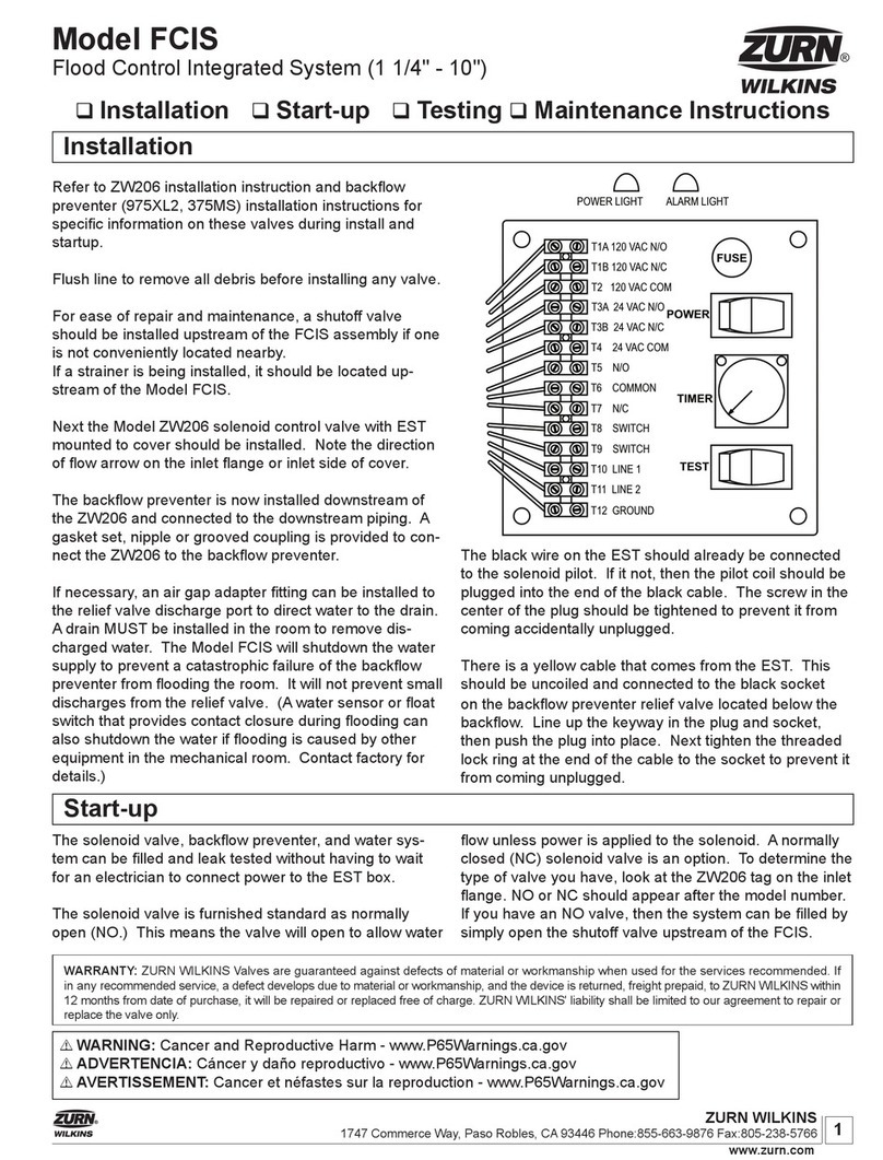
Zurn Wilkins FCIS User manual

Zurn Wilkins

Zurn Wilkins FCIS User manual

Zurn Wilkins ZW209 Manual

Zurn Wilkins

Zurn Wilkins ZW209 Manual

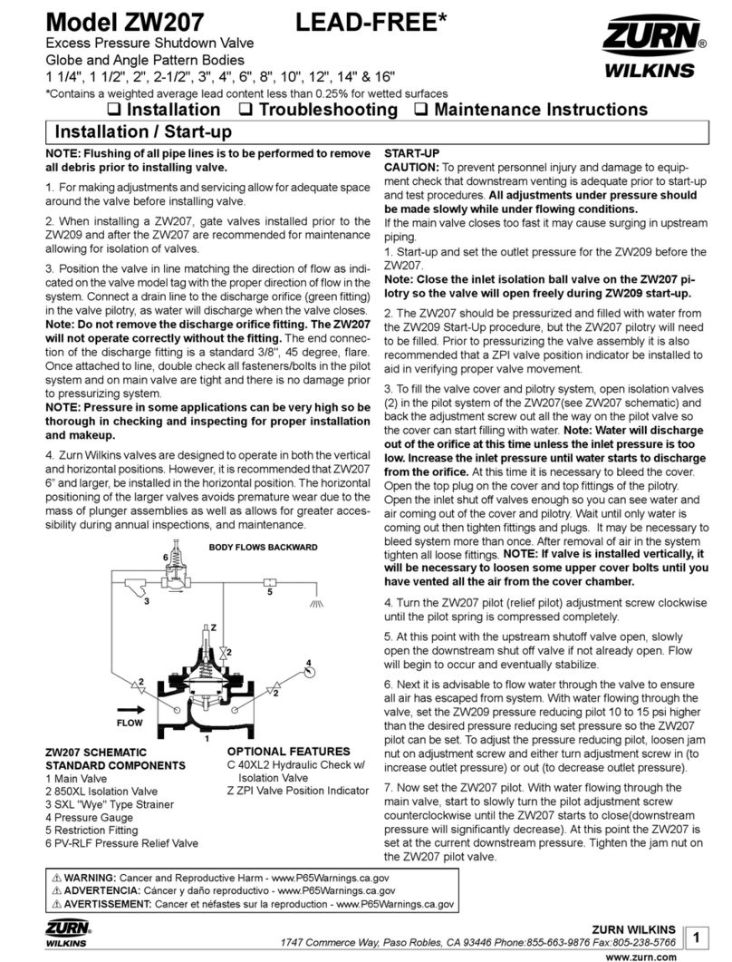
Zurn Wilkins ZW207 Manual

Zurn Wilkins

Zurn Wilkins ZW207 Manual

Zurn Wilkins ZW209FP Installation manual

Zurn Wilkins

Zurn Wilkins ZW209FP Installation manual

Zurn Wilkins ZW209H User manual

Zurn Wilkins

Zurn Wilkins ZW209H User manual

Zurn Wilkins 375 User manual

Zurn Wilkins

Zurn Wilkins 375 User manual

Zurn Wilkins 375 User manual

Zurn Wilkins

Zurn Wilkins 375 User manual

Zurn Wilkins 4-ZW207 Manual

Zurn Wilkins

Zurn Wilkins 4-ZW207 Manual

Zurn Wilkins P4000A Installation manual

Zurn Wilkins

Zurn Wilkins P4000A Installation manual

Zurn Wilkins ZW205 Technical specifications

Zurn Wilkins

Zurn Wilkins ZW205 Technical specifications

Zurn Wilkins 6-ZW209HP Manual

Zurn Wilkins

Zurn Wilkins 6-ZW209HP Manual

Popular Control Unit manuals by other brands

DSE 4110 operating manual

DSE

DSE 4110 operating manual

CAME R Series manual

CAME

CAME R Series manual

Sailor COMPACT HF SSB T2130 Technical manual

Sailor

Sailor COMPACT HF SSB T2130 Technical manual

Dräger Scio Four manual

Dräger

Dräger Scio Four manual

Fermax 2460 Technical book

Fermax

Fermax 2460 Technical book

Festo MS4-A-IPM-80 Assembly instructions

Festo

Festo MS4-A-IPM-80 Assembly instructions

LOVATO ELECTRIC EXP10 30 quick start guide

LOVATO ELECTRIC

LOVATO ELECTRIC EXP10 30 quick start guide

Combat HVAC NRG Control Installation, operation and service manual

Combat HVAC

Combat HVAC NRG Control Installation, operation and service manual

FAAC E024 manual

FAAC

FAAC E024 manual

ETAS ES592.1 user guide

ETAS

ETAS ES592.1 user guide

Propox MMnet103 user manual

Propox

Propox MMnet103 user manual

CLA-VAL 60-73 manual

CLA-VAL

CLA-VAL 60-73 manual

Quanum Gyro user manual

Quanum

Quanum Gyro user manual

Digiplex DGP2-ZX1 instructions

Digiplex

Digiplex DGP2-ZX1 instructions

Vauban Systems V-EXT4+ technical information

Vauban Systems

Vauban Systems V-EXT4+ technical information

Armstrong-Yoshitake, Inc. GD-30 Installation and maintenance instructions

Armstrong-Yoshitake, Inc.

Armstrong-Yoshitake, Inc. GD-30 Installation and maintenance instructions

ABB IMASI13 instructions

ABB

ABB IMASI13 instructions

Simons Voss Technologies RouterNode quick guide

Simons Voss Technologies

Simons Voss Technologies RouterNode quick guide

manuals.online logo
manuals.online logoBrands
  • About & Mission
  • Contact us
  • Privacy Policy
  • Terms and Conditions

Copyright 2025 Manuals.Online. All Rights Reserved.