1
INSTALLATION
NOTE: Prior to installation of the ZW209FP, ensure that all debris is
ushed out the piping system before installed.
1. During the installation of a ZW209FP in a sprinkler system, Underwriter
Laboratories (UL) requires NFPA 13 “Standard for Installation of Sprin-
kler Systems” be followed.
2. Upon installation UL also requires that the ZW209FP be tested in
accordance with NFPA 13 or NFPA 14. Thereafter the valve shall be
inspected, tested, and maintained in accordance to NFPA 25 “Standard
for the Inspection, Testing, and Maintenance of Water-Based Fire Pro-
tection Systems”. NOTE: Initial testing must be done with the design
inlet pressure so the proper outlet pressure can be veried.
3. For making adjustments and servicing allow for adequate space
around the valve.
4. When installing a ZW209FP valve gate valves installed on both inlet and
outlet are recommended for maintenance allowing for isolation of valve.
5. Position the ZW209FP in line matching the direction of ow as indi-
cated on the valve model tag with the proper direction of ow in the
system. Once attached to line double check all fasteners/bolts in the
pilot system and on main valve are tight and there is no damage prior
to pressurizing system.
NOTE: Pressure in some applications can be very high so be thor-
ough in checking and inspecting for proper installation and makeup.
6. Valves installed in sprinkler or standpipe systems shall have the fol-
lowing:
a) Unions or rubber gasket ttings installed immediately upstream
or downstream to permit replacement.
b)A relief valve (at least ½” size and 175 psi max.) installed on the
downstream side and plumbed to a safe drainage.
c) Pressure gauges installed on the inlet and outlet.
d)Shall not be set for less than 50 psi.
Installation Start-up Maintenance Instructions
Model ZW209FP
Fire Protection Pressure Reducing Valve Assembly
Globe and Angle Pattern Bodies
8" & 10"
ZURN WILKINS
1747 Commerce Way, Paso Robles, CA 93446 Phone:855-663-9876 Fax:805-238-5766
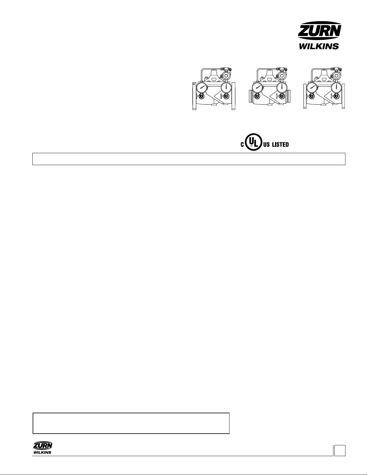
ZW209FP
Class 300 Flanged
Max 300 psi Inlet
ZW209FPG
Grooved
Max 300 psi Inlet
ZW209FPX
Class150 Flanged
Max 250 psi Inlet
7. It is suggested that a line size tee connection be installed downstream
of sprinkler system valves to allow full ow testing as required every
ve years per NFPA 25.
8. Bleed all trapped air from supply riser and sprinkler system. Trapped
air may cause outlet pressure uctuations at low ows.
9. Zurn Wilkins valves are designed to operate in both the vertical and
horizontal positions. However, it is recommended that ZW209FP’s 6” and
larger, be installation in the horizontal position. The horizontal position-
ing of the larger valves avoids premature wear due to mass of plunger
assemblies as well as allows for greater accessibility during annual
inspections, and maintenance.
START-UP
CAUTION: To prevent personnel injury and damage to equipment
check that downstream venting is adequate prior to start-up and test
procedures. All adjustments under pressure should be made slowly
while under owing conditions. If the main valve closes too fast it
may cause surging in upstream piping.
1. Slowly open the upstream shutoff valve only enough to ll main valve
assembly and pilot system. Prior to pressurizing the valve assembly it
is also recommended that a ZPI valve position indicator be installed
to aid in verifying proper valve movement.
2. As the valve is lling with water, it is necessary to bleed the main valve
and pilot system of air. To vent air, partially open or loosen the highest
plugs or ttings in the system. The ZPI valve position indicator is a
great location, as it has a test cock at the top to vent air pressure. It
may be necessary to bleed system more than once. After removal of
air in the system tighten all loose ttings. NOTE: If valve is installed
vertically, it will be necessary to loosen some upper cover bolts until
you have vented all the air from the cover chamber.
3. At this point with the upstream shutoff valve partially open, slowly open
the downstream shut off valve. Flow will begin to occur and pressure
should build up in valve and eventually stabilize.
Installation / Start-up
DESCRIPTION
The Zurn Wilkins ZW209FP pilot operated pressure reducing valve is
designed specically for re suppression systems to reduce high inlet
pressures to a safe and stable outlet pressure. The pilot assembly
reacts to changes in downstream pressure allowing the main valve to
modulate between the closed and open position ensuring a constant
downstream set pressure. Once the downstream pressure reaches
the pilot setting, the main valve will seal shut preventing damage
downstream. Pressure regulation is not dependent upon ow rate,
resulting in minimal pressure loss through the valve. In addition the
ZW209FP comes standard with red epoxy coating internally and
externally for corrosion protection, as well as isolation valves and
pressure gauges for quick and easy maintenance or repair. The
ZW209FP is available in both globe and angle pattern bodies.
ZW209FPTH
Threaded
Max 300 psi Inlet
www.zurn.com
!WARNING: Cancer and Reproductive Harm - www.P65Warnings.ca.gov
!ADVERTENCIA: Cáncer y daño reproductivo - www.P65Warnings.ca.gov
!AVERTISSEMENT: Cancer et néfastes sur la reproduction - www.P65Warnings.ca.gov


