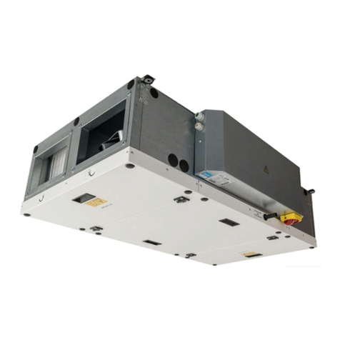
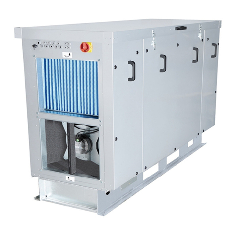
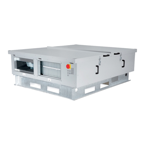
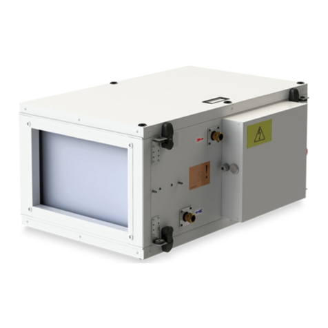
2VV ALFA 85 Owner's manual

Complete Instructions
INSTALLATION AND OPERATION
ALFA 85
EN
v7

22 VV. Creating innovative solutions for you and your business since 1995.
CONTENT
1. BEFORE YOU START 3
2. UNPACKING 4
3. MAIN COMPONENTS 5
4. DIMENSIONS 6
5. TECHNICAL PARAMETERS 17
6. INSTALLATION 20
7. FIRST OPERATION 48
8. MAINTENANCE 49
9. SERVICE 49
10. FAULTS REMOVAL 55
11. WIRING DIAGRAM 56
12. CONCLUSION 65

3
2 VV. Creating innovative solutions for you and your business since 1995.
1. BEFORE YOU START
For better orientation you will nd following symbols in the text hereof. Following table
shows symbols and their meaning.
Symbol Meaning
ATTENTION! Warning or notication
READ CAREFULLY! Important instructions
YOU WILL NEED Advices and practical information
TECHNICAL DATA Detail technical information
Link to another part of the user
guide
Before installation, please read carefully the guide “Safety for Ventilation Units” where you can nd instructions for correct and safe
operation of the product.
This manual includes important instructions for safe connection of the ventilation unit. Before connecting the unit, please read follow
all instructions! The manufacturer reserves the right to make changes including technical documentation without previous notication.
Please keep this manual for further references. Consider this manual integral part of the product.
EC DECLARATION OF COMPLIANCE
The product was designed, and manufactured to comply with all relevant provisions and is in compliance with the requirements of the
European Parliament and of the Council of the EU, including the amendment, which it was classied under. It is considered safe when
installed in the specied conditions and operated according to the instructions of the operations manual. It was assessed according to
harmonized European standards listed in the relevant EC declaration of conformity were applied.
For the current and full version of the EC declaration of conformity visit www.2vv.cz

42 VV. Creating innovative solutions for you and your business since 1995.
2. UNPACKING
2.1 Product InsPectIon
READ CAREFULLY!
• Upon delivery, check the product packaging for possible
damage. In the event of damage to the packaging notify
the carrier. If no complaint is led in a timely manner, sub-
sequent requests will not be considered.
• Check whether the product is appropriate for your order.
If the product type does not match, do not unpack it and
contact the supplier immediately.
• After unpacking, check the status of the unit and all of its
components. If in doubt, contact the supplier.
• Never use a damaged unit.
• If you fail to unpack the unit immediately after its receipt,
it must be stored in dry rooms at temperatures from +5 ° C
to +35 ° C.
Components Included
READ CAREFULLY!
• If the ventilation unit was exposed to temperatures lower
than 0 ° C during transport, please unpack unit and let it sit
at room temperature for at least 2 hours before connecting
the unit in order to balance temperature inside unit.
This product must be properly disposed of in accordance
with local laws and regulations. The product contains batte-
ries, so they must be recycled or disposed of separately from
household waste.
When the battery or the product reach the end of their
service life, contact your dealer or local authorities and ask
about recycling options. The separate collection and recyc-
ling of your product and its battery will help to preserve
natural resources and ensure that the product is recycled in
a manner that protects human health and the environment.
Communication cable is not part of delivery and is requi-
red for proper operation of unit.
Recommended cable type: UTP CAT5 class
5
2 VV. Creating innovative solutions for you and your business since 1995.
3. MAIN COMPONENTS
Unit control
Main switch with cable of 1.5 m
(except for 700 series that has a supply cable of
CEE 7/16“Europlug“ type)
External temperature sensor (CT-ROM)
(shielded twin cable max. 50 m)
Fans Condensate drain
Unit controls box
Filters
Removable panels
access to the unit

62 VV. Creating innovative solutions for you and your business since 1995.
4. DIMENSIONS
ALFA 85 700 V - right version with duct system connection from the side
ALFA 85 700 V - left version with duct system connection from the top
Water heater /C-O (change over) external module for units ALFA 85 700
ALFA 85 700 A B
700 water heater G 1/2" G 1/2"
700 heater/cooler G 3/4" G 3/4"
700 direct evaporator 5/8" 5/8"
22
A
B
410
395
530
250
115 729
844
1066
950
656
697
246
220
329
145
391
4x∅250
391
180
245
335

7
2 VV. Creating innovative solutions for you and your business since 1995.
4. DIMENSIONS
ALFA 85 700 U - left version with duct system connection from the top
ALFA 85 700 U - right version with duct system connection from the top
655
250 (4x)
170 245 170 220
240 185
1075
1015
955
695
655
Fan / Ventilator
Heat exchanger / Wärmetauscher
Filter / Filter
Regulation / die Regulation
Condesate exhaust / Kondensatausscheidung
Afterheater / Nachheizeinrichtung / DX / CO
By-pass ap / By-pass Klappe
Preheater / Vorwärmer
Operational diagram
Funktionsschema
Fan / Ventilator
Heat exchanger / Wärmetauscher
Filter / Filter
Regulation / die Regulation
Condesate exhaust / Kondensatausscheidung
Afterheater / Nachheizeinrichtung / DX / CO
By-pass ap / By-pass Klappe
Preheater / Vorwärmer
Operational diagram
Funktionsschema
1128
1076
1070
697
657
220
170
245
170
230
186
4x ∅250
230 185
170 220 170 245
1075 655
695
1015
955
655
250 (4x)
POWER PLAY 700V
1128
1076
1070
697
657
220
170
245
170
230
186
4x ∅250

82 VV. Creating innovative solutions for you and your business since 1995.
4. DIMENSIONS
ALFA 85 1000 U - right version with duct system connection from the top
ALFA 85 1000 U – left version with duct system connection from the top
ALFA 85 1000 V - right version with duct system connection from the side
ALFA 85 1000 Ø A Ø C C D
heater/cooler G 3/4" G 3/4" 505 580
water heater G 1/2" G 1/2" 505 580
direct evaporator 5/8" 5/8" 505 580
ALFA 85 1000 Ø A Ø C C D
heater/cooler G 3/4" G 3/4" 825 900
water heater G 1/2" G 1/2" 825 900
direct evaporator 5/8" 5/8" 825 900
ALFA 85 1000 Ø A Ø C C D
heater/cooler G 3/4" G 3/4" 525 595
water heater G 1/2" G 1/2" 525 595
direct evaporator 5/8" 5/8" 525 595
115
1458
1285
505
580
178
203
280
60
∅22
B
A
857
817
705
1416
180 295 315 306
276265
4x∅250
115 1285
1458
851
920
178
203
280
60
A
B
∅22
857
817
705
1416
306 315
265 276
295 180
276265
4x∅250
1534
1418
950
824
115
527
60
602
203
178
483
280
A
B
309 200
815
855
375
509
4x∅315
509
309

9
2 VV. Creating innovative solutions for you and your business since 1995.
4. DIMENSIONS
ALFA 85 1500/2000 U/V - right version with duct system connection from the top
ALFA 85 1500/2000 Ø A Ø C C D
heater/cooler G 1" G 1" 520 595
water heater G 3/4" G 3/4" 520 595
direct evaporator 1 1/8" 7/8" 520 595
ALFA 85 1500/2000 U/V - left version with duct system connection from the top
ALFA 85 1500/2000 Ø A Ø C C D
heater/cooler G 1" G 1" 930 1005
water heater G 3/4" G 3/4" 930 1005
direct evaporator 1 1/8" 7/8" 930 1005
115
1137
1022
521
595
178
203
563
360
60
A
B
∅22
807
410 252
450285
251 410
955
915
287450
1518
257400
284 950 284
8x∅355
115
1137
1022
521
595
178
203
563
360
60
A
B
∅22
807
410 252
450285
251 410
955
915
287450
1518
257400
284 950 284
8x∅355
115
1137
1022
936
1006
178
203
563
360
60
∅22
B
A
955
915
287450
252 410
252410
285 450
807
1518
400 257
284
950 284
8x∅355
115
1137
1022
936
1006
178
203
563
360
60
∅22
B
A
955
915
287450
252 410
252410
285 450
807
1518
400 257
284 950 284
8x∅355

10 2 VV. Creating innovative solutions for you and your business since 1995.
4. DIMENSIONS
ALFA 85 3000/4500 V - right version with duct system connection from the side
ALFA 85 3000/4500 Ø A Ø C C D
heater/cooler G 1" G 1" 990 1060
water heater G 3/4" G 3/4" 990 1060
direct evaporator 1 3/8" 1 1/8" 990 1060
ALFA 85 3000/4500 V - left version with duct system connection from the side
1822
614 590 614
115 1229
778
843
480
60
178
203
A
B
∅22
595 317
500
600
1172
1212
1242
1040
1822
614 590 614
1344
115 1229
985
1153
178
203
480
60
B
A
∅22
317
1172
600
1212
1242
595
1040
524
624

11
2 VV. Creating innovative solutions for you and your business since 1995.
ALFA 85 3000/4500 U - right version with duct system connection from the top
ALFA 85 3000/4500 Ø A Ø C C D
heater/cooler G 1" G 1" 990 1060
water heater G 3/4" G 3/4" 990 1060
direct evaporator 1 3/8" 1 1/8" 990 1060
1822
614 590 614
1344
115 1229
778
843
480
60
178
203
683
A
B
∅22
284
286550
284
286550
1172
1212
1241
1040
424
424
1822
614 590 614
1344
115 1229
778
843
480
60
178
203
683
A
B
∅22
284
286550
284
286550
1172
1212
1241
1040
424
424
4. DIMENSIONS

12 2 VV. Creating innovative solutions for you and your business since 1995.
ALFA 85 3000/4500 U - left version with duct system connection from the top
ALFA 85 3000/4500 Ø A Ø C C D
heater/cooler G 1" G 1" 990 1060
water heater G 3/4" G 3/4" 990 1060
direct evaporator 1 3/8" 1 1/8" 990 1060
4. DIMENSIONS
1822
614 590 614
985
1153
178
203
60
480
B
A
∅22
1212
1172
1241
1040
286
284
550
286
284
550
424
424

13
2 VV. Creating innovative solutions for you and your business since 1995.
4. DIMENSIONS
ALFA 85 5500/7500 V - right version with duct system connection from the side
ALFA 85 5500/7500 Ø A Ø C C D
heater/cooler 1 1/2" 1 1/2" 810 710
water heater 3/4" 3/4" 810 710
direct evaporator 1 5/8" 1 1/8" 810 710
1655
1930
570
570
620
60
D
C
190
215
790
A
B
1520
600
624
1200
1224
759 759
760 509 385
A B
C D
PP55,70HRSECW
G 1 1/2" G 1 1/2"
810 710
PP55,70HRSECV
G 3/4" G 3/4"
810 710
PP55,70HRSECX
1 5/8" 1 1/8"
810 710
PP55,70HRSECE
----
PP55,70HRSECN
----

14 2 VV. Creating innovative solutions for you and your business since 1995.
ALFA 85 5500/7500 V - left version with duct system connection from the side
ALFA 85 5500/7500 Ø A Ø C C D
heater/cooler 1 1/2" 1 1/2" 810 710
water heater 3/4" 3/4" 810 710
direct evaporator 1 5/8" 1 1/8" 810 710
1930
567 790 567
115
1530
1645
1090
1292
178
202
620
75
B
A
385760385
1518
1558
759 759
1200
600
624
1224
1930
567 790 567
115 1530
1645
1090
1292
178
202
620
75
B
A
385760385
1518
1558
759 759
1200
600
624
1224
4. DIMENSIONS

15
2 VV. Creating innovative solutions for you and your business since 1995.
4. DIMENSIONS
ALFA 85 9000/12000 V - right version with duct system connection from the side
ALFA 85 9000/12000 Ø A Ø B
heater/cooler 2" 2"
water heater 1" 1“
direct evaporator 1 1/8" 2 1/8"
2250
717 717 810
1780
920
715
75
A
B
1020
103
22
63
1895
115
1720
1760
1800
1398
698
724
1424
136
A B
PP085, PP100 T
G 1 G 1
PP085, PP100 CO
G 2" G 2"
PP085, PP100 DX
1 1/8" 2 1/8"

16 2 VV. Creating innovative solutions for you and your business since 1995.
4. DIMENSIONS
ALFA 85 9000/12000 V - left version with duct system connection from the side
ALFA 85 9000/12000 Ø A Ø B
heater/cooler 2" 2"
water heater 1" 1“
direct evaporator 1 1/8" 2 1/8"
717 810 717
2250
1780 115
1895,4
A
B
75
715
22
63
1260
1460
698
1398
724
1424
136
1720
1760
1800
A B
PP085, PP100 T
G 1 G 1
PP085, PP100 CO
G 2" G 2"
PP085, PP100 DX
1 1/8" 2 1/8"

17
2 VV. Creating innovative solutions for you and your business since 1995.
5. TECHNICAL PARAMETERS
Electrical characteristics of EC motors
Alfa 85 V/U Voltage
(V)
Frequency
(Hz)
Number of fansin
the unit
Fan input power
(W)
Current
(A)
Flowrate
(m3/h) IP
700 230 50 2 200 1,2 700 44
1000 230 50 2 455 2,8 900 54
1500 230 50 2 455 2,8 1600 54
2000 230 50 2 715 3,1 2500 54
3000 400 50 2 1000 1,63 3000 54
4500 400 50 2 1700 2,6 4500 54
5500 V 400 50 2 1850 2,9 5500 54
7500 V 400 50 2 2730 4,2 7000 54
9000 V 400 50 2 3450 5,3 8500 55
12000 V 400 50 2 5700 9 10000 55

18 2 VV. Creating innovative solutions for you and your business since 1995.
5. TECHNICAL PARAMETERS
Model with electrical heater
Alfa 85 V/U Voltage
(V)
Frequency
(Hz)
Input power
(kW)
Current per phase
(A)
700 230 50 2,4 11,7
1000 400 50 4 10,2
1500 400 50 5,5 12,3
2000 400 50 8,5 17
3000 400 50 11 16,5
4500 400 50 18,5 27,1
5500 V 400 50 27,6 40,7
7500 V 400 50 35,5 52
9000 V 400 50 40,8 60,6
12000 V 400 50 50,1 74,9
Model without electrical heater / model with water heater / model with C/O (change-over) / model with direct evaporator (DX).
Alfa 85 V/U Voltage
(V)
Frequency
(Hz)
Input power
(kW)
Current per phase
(A)
700 230 50 0,4 3
1000 230 50 0,95 5,8
1500 230 50 1 6,2
2000 230 50 1,5 6,8
3000 400 50 2 3,5
4500 400 50 3,5 5,8
5500 V 400 50 3,5 5,8
7500 V 400 50 3,5 9
9000 V 400 50 7,2 12,1
12000 V 400 50 11,7 19,5
Model with water heater:
ALFA 85 V/M
Nominal
ow rate
(m3/h)
Nominal output
(kW)
Exhaust
temperature
(°C)
Pressure loss - water
(kPa)
Water ow rate
(m3/h)
Pressure loss - air
(Pa) Connection
700 700 5,59 33 9,52 0,25 15,11 1/2
1000 900 7,92 35,4 6,47 0,35 9,42 1/2
1500 1600 13,71 34,7 18,74 0,6 12,16 3/4
2000 2500 17,77 30,5 30,02 0,78 26,39 3/4
3000 3000 24,17 33,2 12,16 1,07 14,13 3/4
4500 4500 30,51 29,6 18,74 1,34 28,55 3/4
5500 V 5500 42,16 32,1 10,1 1,86 14,91 3/4
7500 V 7000 48,39 29,9 13,05 2,13 22,66 3/4
9000 V 9000 63,19 31,4 9,03 3,22 28,65 1“
12000 V 12000 69,28 30 10,69 3,53 38,36 1“
*Data for the fall of water 90/70Tinlet = 10°C

19
2 VV. Creating innovative solutions for you and your business since 1995.
Model with C/O (change-over) cooling:
ALFA 85 V/M
Nominal
ow rate
(m3/h)
Nominal output
(kW)
Exhaust
temperature
(°C)
Pressure loss - water
(kPa)
Water ow rate
(m3/h)
Pressure loss - air
(Pa) Connection
700 700 4,53 15,2 17,3 0,78 50 3/4
1000 900 6,05 14,8 8,5 1,04 31 3/4
1500 1600 9,57 15,7 6,3 1,64 40 1
2000 2500 12,91 16,8 11,1 2,21 88 1
3000 3000 19,17 15,3 12,9 3,29 47 1
4500 4500 25,28 16,3 21,4 4,34 96 1
5500 V 5500 37,35 14,8 26,3 6,41 50 1 1/2
7500 V 7000 44,29 15,5 35,8 7,6 76 1 1 /2
9000 V 9000 51,85 15,7 15,6 8,89 61 2“
12000 V 12000 57,76 16,1 18,9 9,91 81 2“
*Data the fall of water 7/12Tinlet = 25°C, RH 70%
Model with C/O (change-over) heating:
ALFA 85 V/M
Nominal
ow rate
(m3/h)
Nominal output
(kW)
Exhaust
temperature
(°C)
Pressure loss - water
(kPa)
Water ow rate
(m3/h)
Pressure loss - air
(Pa) Connection
700 700 6,68 37,5 2,5 0,29 46 3/4
1000 900 9,04 39 1,3 0,39 28 3/4
1500 1600 14,74 36,6 1,0 0,64 36 1
2000 2500 20,03 33,1 1,8 0,87 80 1
3000 3000 28,52 37,4 1,9 1,24 43 1
4500 4500 37,84 34,3 3,1 1,65 86 1
5500 V 5500 54,22 38,4 3,6 2,36 45 1 1/2
7500 V 7000 118,91 59 14,3 5,24 71 1 1/2
9000 V 9000 76,17 35,8 2,2 3,32 55 2“
12000 V 12000 84,89 34,5 2,65 3,7 73 2“
*Data the fall of water 60/40Tinlet = 10°C
Model with DX (Direct evaporator):
ALFA 85 V/M
Nominal
ow rate
(m3/h)
Nominal output
(kW)
Exhaust
temperature
(°C)
RH
(%)
Pressure
loss - coolant
(kPa)
Pressure loss - air
(Pa)
Connection
(gas)
Connection
(liquid)
700 700 4,98 14,6 90,7 17,9 47 5/8 5/8
1000 900 7,17 13,5 91,8 22,8 29 5/8 5/8
1500 1600 12,12 14 91,2 12,5 37 int 28,2 7/8
2000 2500 16,33 15,5 89,5 21,0 80 int 28,2 7/8
3000 3000 22,68 14,1 90,9 31,9 42 1 3/8 1 1/8
4500 4500 29,28 15,5 89,3 50,0 87 1 3/8 1 1/8
5500 V 5500 41,38 14,1 90,7 26,0 45 1 5/8 1 1/8
7500 V 7000 48,47 15 89,8 34,3 68 1 5/8 1 1/8
9000 V 9000 49,57 14,5 81,7 28,1 56 2 1/8 1 1/8
12000 V 12000 54,65 15,1 80,5 33,4 75 2 1/8 1 1/8
Data: Tinlet = 25°C, 70% RH, evap. temperature 5°C , coolant R410A
5. TECHNICAL PARAMETERS

20 2 VV. Creating innovative solutions for you and your business since 1995.
The unit is not designed for air containing ammable or ex-
plosive mixtures, chemical vapours, heavy dust, soot, grease,
toxins, pathogenic organism, etc.
The electric protection index of units is IP 43 (intended for
outdoor environments).
6.1-1 Access distances needed for servicing
the units
Models V/U a
700 800
1000 800
1500 900
2000 900
3000 1200
4500 1200
5500 1500
7500 1500
9000 1500
12000 1500
6.1 seLect unIt LocAtIon
TECHNICAL DATA
Units intended for outdoor installation may only be installed
in the an unprotected outdoor environment with with tem-
peratures between -20°C to +60°C
For outdoor installations it is necessary to use rain protected
roofs. Outdoor installation is possible on side connection
units only.
Rein-protected roofs
ALFA 85 V code
700 ROOF-HR85-070
1000 ROOF-HR85-100
1500/2000 ROOF-HR85-150-200
3000/4500 ROOF-HR85-300-450
5500/7000 ROOF-HR85-550-750
9000/12000 ROOF-HR85-900-12K
• The unit should use air ow with temperatures between
-20°C to +60°C and relative humidity up to 90 %.
6. INSTALLATION
60
a
Other manuals for ALFA 85
2
Table of contents
Other 2VV Fan manuals

2VV
2VV VENUS AirGENIO Comfort User manual

2VV
2VV Whisper Air HRWA1-040 Series Guide

2VV
2VV ALFA 85 User manual

2VV
2VV FINESSE EC User manual

2VV
2VV ALFA 95 II horizontal User manual

2VV
2VV HRFL2 User manual

2VV
2VV Essensse Neo VCES2-B Series User manual

2VV
2VV VENUS READY Owner's manual

2VV
2VV ALFA 95 II vertical User manual

2VV
2VV ALFA 85 User manual
Popular Fan manuals by other brands

Progress Lighting
Progress Lighting AirPro P250000 installation manual

CLIMTEC
CLIMTEC RD Series Technical Passport

Honeywell
Honeywell HSF1630E Operation instructions

Daikin
Daikin DQ-P-70-AH-H Installation & operation manual

Salda
Salda RIRS 700VE EKO 3.0 Technical manual

Sygonix
Sygonix 2616627 installation instructions