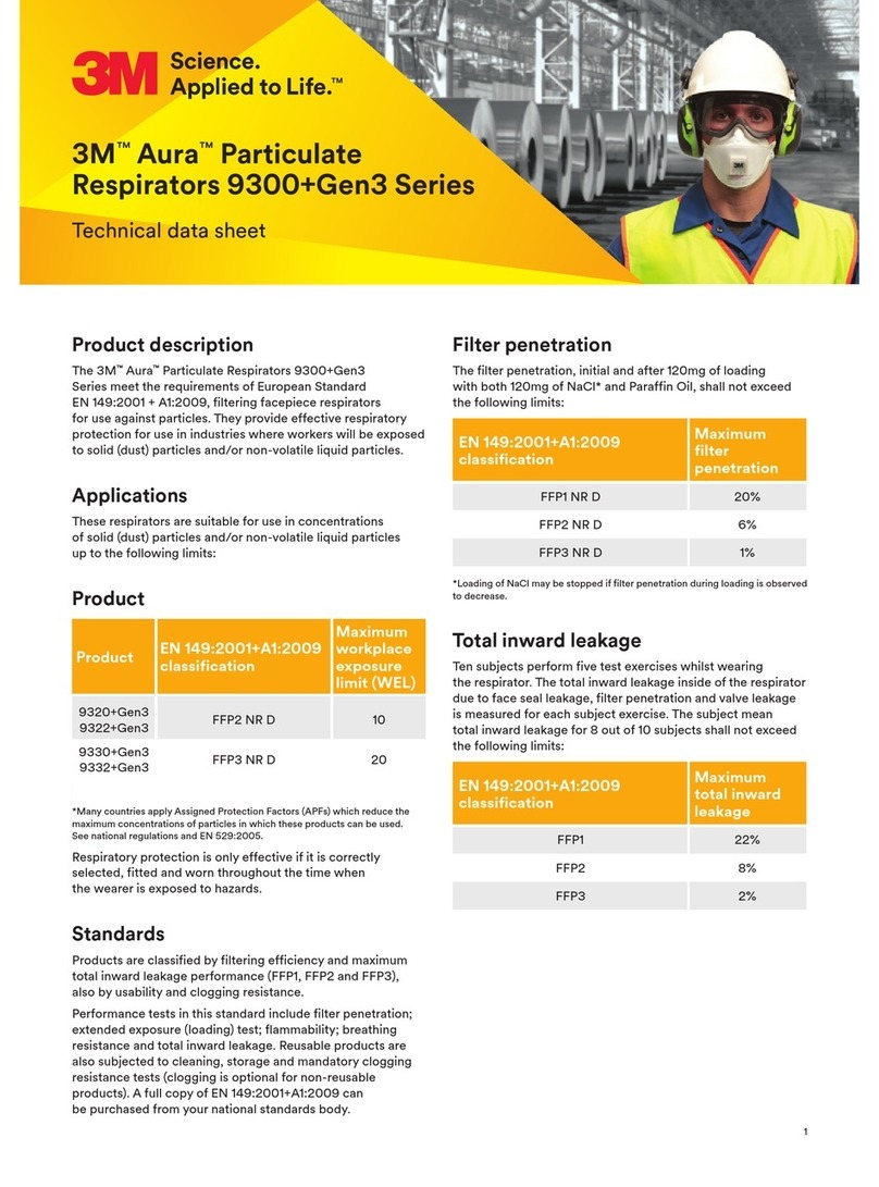
3M SCOTT AIR-PAK X3 PRO Configuration guide

INSPECTION & CLEANING
INSTRUCTIONS
3M™ SCOTT™ AIR-PAK™ X3 PRO
Self-Contained Breathing Apparatus (SCBA)
CGA & SNAP-CHANGE
Pressures 2.2, 4.5, 5.5
READ ALL INSTRUCTIONS BEFORE USE
P/N 595360-01 Rev G 202004

All information, illustrations, and specifications in this manual are based on the latest product information available at
the time of publication. 3M reserves the right to make changes at any time without notice.
The contents of this manual may not be used, reproduced, or disclosed to any third party in whole or in part without
obtaining express written permission and authorization from 3M.
Cautionary Notice
While the manufacturer has attempted to detail in this manual all areas of possible danger to personnel in connection
with the use and servicing of this equipment, personnel should use caution when installing, inspecting, operating, and
servicing this equipment, especially when handling pressurized air cylinders. When maintaining or operating all
electronic equipment, care should be taken to avoid electrical shock in all circuits where substantial currents or
voltages may be present through design or component failure. Caution should be observed in lifting and hoisting
heavy equipment.
The manufacturer is specifically not liable for any damage or injury arising out of a user’s failure to follow the
instructions contained in this manual or failure to exercise due care and caution in the installation, operation,
inspection, and service of this equipment.
Import and Export
The international transport of this equipment and any related documentation is regulated under United States export
laws and regulations and may be regulated by the import or export laws and regulations of other countries.
If you have any questions or concerns regarding these regulations, contact 3M at 1-800-247-7257 (704-291-8300
outside the continental United States).
Questions or Concerns
If you have any questions or concerns regarding use of this equipment, contact your authorized 3M distributor, or
contact 3M at 1-800-247-7257 (704-291-8300 outside the continental United States) or
For all National Fire Protection Association (NFPA)-compliant versions of this respirator, report any operational
malfunctions to the certification agency Safety Equipment Institute (SEI), 1307 Dolley Madison Blvd, Suite 3A,
McLean, VA 22101, (703) 442-5732, Fax (703) 442-5756.
For all National Institute for Occupational Safety and Health (NIOSH)-compliant versions of this respirator, report
any complaints of damage, malfunction or failure of the breathing apparatus that may represent a hazard to the user
to the certification agency NIOSH/NPPTL/Respirator Branch, P.O. Box 18070, Pittsburgh, PA 15236, (412)
386-4000.

P/N 595360-01 Rev G 202004 3
Contents
About This Manual ...................................................................................................................... 5
Intended Readers........................................................................................................................................5
How to Read This Manual ........................................................................................................................5
Warnings, Cautions, and Notes .......................................................................................................5
Before You Begin ........................................................................................................................................6
Maintenance and Repairs ..................................................................................................................6
Respirator Testing ...............................................................................................................................6
Retirement Criteria and Considerations ........................................................................................ 7
Safety Information ...................................................................................................................... 9
All 3M Scott Fire & Safety Products......................................................................................................9
3M Scott Air-Pak SCBAs..........................................................................................................................9
Chapter 1 Inspecting the Respirator ............................................................................................................11
Before You Begin ....................................................................................................................................... 11
Inspecting the Respirator Components...............................................................................................12
Performing a General Inspection ...................................................................................................12
Inspecting the Breathing Air Cylinder .......................................................................................... 13
Inspecting the RIC/UAC Connection .......................................................................................... 14
Inspecting the Facepiece ................................................................................................................ 15
Inspecting the Regulator ..................................................................................................................17
Performing Operational Testing............................................................................................................ 19
General Testing .................................................................................................................................. 19
Testing the Regulator ...................................................................................................................... 20
Testing the Heads-Up Display ........................................................................................................21
Testing the Sensor Module Lights ................................................................................................23
Testing the Batteries .........................................................................................................................24
Chapter 2 Soft Goods Assembly & Disassembly ..................................................................................... 25
Detaching the Shoulder Harness and Waist Pad..............................................................................25
Attaching the Shoulder Harness and Waist Pad...............................................................................32
Chapter 3 Cleaning & Storing the Respirator ............................................................................................41
Before You Begin ...................................................................................................................................... 41
Cleaning the Respirator...........................................................................................................................42
Cleaning the Facepiece ...................................................................................................................42
Cleaning the Mask-Mounted Regulator ..................................................................................... 44
Cleaning the Shoulder Harness and Waist Pad .........................................................................47
Spot Cleaning the Shoulder Harness and Waist Pad ........................................................................... 47
Machine Washing the Shoulder Harness and Waist Pad .................................................................. 48
Drying the Shoulder Harness and Waist Pad......................................................................................... 49
Storing the Respirator............................................................................................................................. 50
Chapter 4 Replacing Batteries ......................................................................................................................51
Before You Begin ...................................................................................................................................... 51
Replacing Batteries in Respirators with PASS................................................................................... 51
P/N
Rev G
202004
4 P/N 595360-01 Rev G 202004

P/N 595360-01 Rev G 202004 5
ABOUT THIS MANUAL
This manual provides inspection and cleaning instructions for the 3M Scott Air-Pak X3 Pro SCBA.
Intended Readers
3M provides manuals for individuals with different levels of training. This manual is written for Trained Operators.
•A Trained Operator is an individual who has had minimum-level training in the use of 3M Scott Fire & Safety
equipment in an immediately dangerous to life or health (IDLH) environment. This individual is often a firefighter
or the wearer of an SCBA. He or she is familiar with the instructions provided in this manual and is capable of
performing basic maintenance tasks (e.g., replacing batteries) as outlined.
•A Certified Technician is an individual who has successfully completed the Air Supplied Certified Technician II
class offered by 3M. Certified technicians are able to use specialized equipment, including the Posi 3 USB™ 1
SCBA testing equipment, and are able to make repairs to the SCBA that involve the air flow path.
How to Read This Manual
Warnings, Cautions, and Notes
Throughout this manual, special references are made when deemed important. The following classifications
distinguish these references by their level of importance:
1. Posi3 USB is a trademark of Honeywell Analytics, Inc., Lincolnshire, IL.
WARNING
Indicates a hazardous situation which, if not avoided, could result in serious injury or death
CAUTION
Indicates a hazardous situation which, if not avoided, could result in minor or moderate injury and/or
property damage
NOTE
Indicates a situation which, if not avoided, could result in property damage
TIP
Indicates helpful information
P/N 595360-01
202004
Rev G

6 P/N 595360-01 Rev G 202004
Before You Begin
Before beginning any procedures, review the manual in its entirety. Thoroughly read all warnings, cautions, and
notes. Acquire all tools and materials listed before beginning any procedure. When performing any maintenance
checks or services on any 3M Scott Fire & Safety product or device, proceed only as far as necessary and as
instructed by this manual.
Maintenance and Repairs
Comply with all instructions and warnings contained in all applicable manuals.
It is your responsibility to obtain and use the most current instructions that apply to the operations being performed.
The instructional material must include the most current materials: manuals or manual modules, Operation and
Maintenance Instructions, Inspection and Cleaning Instructions, Installation and Use Instructions, and any additional
3M-approved support material required to maintain the equipment.
Current service literature is available from 3M. The Certified Technician I Maintenance Training Manual contains
additional maintenance information that goes beyond the routine cleaning and regular operational inspection of the
equipment but is less advanced than Certified Technician II-level maintenance available at a 3M Authorized Service
Center. A person with good mechanical ability using standard hand tools is capable of performing Technician I-level
tasks. Contact 3M or your 3M distributor for details.
Because this equipment may be used to support human life in a hazardous atmosphere, do not attempt maintenance
beyond that described in this instruction or in the Certified Technician I Maintenance Training Manual. If disassembly
or adjustment other than described in this manual or the Certified Technician I Maintenance Training Manual is
required, the equipment must be serviced by a 3M Scott Authorized Service Center in accordance with the
appropriate 3M Scott Fire & Safety Technician Service Manuals. You can arrange service by an Authorized Service
Center through your authorized 3M distributor or by contacting 3M.
If you note a discrepancy while performing operation or maintenance checks and services, tag the equipment as “Out
of Service” and refer it to a 3M Certified Technician II.
While an attempt has been made to address all foreseeable operation/service conditions, exercise careful judgment
in removing from service any equipment that does not appear to function correctly, even if all operator-level
maintenance checks and services have been completed. If there is any doubt regarding the safe operation of the
equipment, remove it from service and tag it for repair.
Respirator Testing
3M recommends that this respirator be inspected and tested by a 3M Scott Authorized Service Center using 3M
Authorized Test Equipment at least once a year. Heavy use and/or severe service conditions may require more
frequent inspection and testing. This recommendation is in addition to all other cleaning and maintenance procedures.
In addition, all air cylinders used with 3M Scott Fire & Safety respirators must be periodically visually inspected and
hydrostatically tested by a licensed cylinder retester. The cylinder inspection and test must be done in accordance
with the appropriate U.S. Department of Transportation (DOT) specification or the applicable DOT exemption.
•Composite fiber overwrapped cylinders must be tested up to their maximum life which, at the time of the
publication of this manual, is 15 years from the date of manufacture. It is the responsibility of your organized
respiratory protection program to arrange for visual inspection and hydrostatic testing of cylinders by a licensed
retester.
•Intervals for hydrostatic testing are established in the appropriate U.S. Department of Transportation (DOT)
specification or applicable DOT exemption, or in the appropriate Transport Canada (TC) Permit of Equivalent
Level of Safety. Refer to the current revision of Safety Precautions for Air-Pak Cylinders, P/N 89080-01, available
upon request from 3M.

BEFORE YOU BEGIN
P/N 595360-01 Rev G 202004 7
Retirement Criteria and Considerations
Retirement criteria and considerations to be determined by technicians with Certified Technician II qualifications in
accordance with NFPA 1852.

8 P/N 595360-01 Rev G 202004
P/N 595360-01 Rev G 202004 9
SAFETY INFORMATION
Read all of the safety information before beginning any of the procedures in this manual. The safety information in
this section is organized as follows:
•“All 3M Scott Fire & Safety Products” on page 9
•“3M Scott Air-Pak SCBAs” on page 9
All 3M Scott Fire & Safety Products
The following safety directives apply to all 3M Scott Fire & Safety products.
•Many 3M Scott Fire & Safety products are intended to support human life in hazardous atmospheres. Failure to
carefully read, understand, and follow the instructions and warnings in this manual may result in serious injury or
death.
•Improper use of this equipment may result in serious injury or death. Improper use includes, but is not limited to,
use without adequate training, disregard of the warnings and instructions contained herein, use of the equipment
for purposes not included in these instructions, and failure to inspect and maintain the equipment.
•Apply only the instructions offered within this manual. Maintenance procedures beyond the scope of this manual
must not be performed. Additional disassembly may cause operation errors and/or component failure and result
in serious injury or death. If a discrepancy or malfunction cannot be corrected using the procedures contained
within this manual, the product must be tagged to indicate that it is unserviceable and referred to a 3M Certified
Technician II for evaluation and repair.
•Exercise caution when using chemicals. Prior to using any chemical substance, thoroughly review and understand
the product label, Safety Data Sheet (SDS), and manufacturer’s use instructions. Chemical substances may
present serious hazards such as flammability and human-specific health hazards, which can affect the nervous
and reproductive systems. Failure to adhere to the manufacturer’s product instructions and warnings may result
in serious injury or death.
•Comply with all instructions and warnings contained in this and all applicable manuals and modules. While an
attempt has been made to address all foreseeable operating conditions, you must exercise careful judgment
when operating any equipment. If there is any doubt regarding the safe operation of equipment, remove the
equipment from service and tag it for repair.
•Failure to use 3M-approved lubricants and replacement parts will invalidate all certifications and warranties
issued to the 3M Scott Fire & Safety product.
•You are responsible for any damage, improper function, or injury as a result of user-applied markings, etchings,
labeling, material additions, or modifications to the equipment.
3M Scott Air-Pak SCBAs
The following safety directives, warnings, and cautions apply to 3M Scott Air-Pak SCBAs.
•Improper use of this respirator may result in serious injury or death. Improper use includes, but is not limited to,
use without adequate training, disregard of the warnings and instructions contained herein, and failure to inspect
P/N 595360-01
202004
Rev G

10 P/N 595360-01 Rev G 202004
and maintain this respirator. Read and understand all instructions before attempting to operate or service this
equipment.
•The information in this instruction is meant to supplement — not replace — the instructions, training, supervision,
maintenance, and other elements of your organized respiratory protection program.
•Use this respirator only in conjunction with an organized respiratory protection program that complies with the
requirements of the following:
•American National Standard Practices for Respiratory Protection, Z88.2, current edition, available from
American National Standards Institute, Inc., 1430 Broadway, New York, NY, 10018
•OSHA Safety and Health Standard 29 CFR 1910, Paragraph 134, available from the US Department of Labor,
Occupational Safety and Health Administration
•Other pertinent nationally recognized standards, such as those of the US Coast Guard or the Department of
Defense
•This product is designed and intended to function properly in reasonable/ordinary firefighting conditions. The
functionality of this product may be compromised by extreme fire conditions.
•Training is required before use of this respirator. Use this respirator only if you have been trained in its use and
only in conjunction with an organized respiratory protection program. Do not use this respirator for purposes
other than those authorized by your respiratory protection program. Do not use this respirator underwater.

P/N 595360-01 Rev G 202004 11
P/N 595360-01
202004
Rev G
CHAPTER 1
INSPECTING THE RESPIRATOR
This chapter describes how to perform a regular operational inspection of a 3M Scott Air-Pak X3 Pro SCBA. Follow
the procedures in this chapter when you first receive the SCBA and during daily or periodic inspection of the SCBA:
•“Before You Begin” on page 11
•“Inspecting the Respirator Components” on page 12
•“Inspecting the Breathing Air Cylinder” on page 13
•“Inspecting the RIC/UAC Connection” on page 14
•“Inspecting the Facepiece” on page 15
•“Inspecting the Regulator” on page 17
•“Performing Operational Testing” on page 19
•“General Testing” on page 19
•“Testing the Regulator” on page 20
•“Testing the Heads-Up Display” on page 21
•“Testing the Sensor Module Lights” on page 23
•“Testing the Batteries” on page 24
Before You Begin
Below is a summary of the requirements and recommendations for operational inspections of respirators:
•Inspect the respirator before each use and after each cleaning. (Clean the respirator after each use. See
“Chapter 3: Cleaning & Storing the Respirator” on page 41.)
•Inspect respirators for emergency use as frequently as required to ensure the respirator will function properly.
The Occupational Safety and Health Administration (OSHA) of the U.S. Department of Labor requires at least
monthly inspection of respirators for emergency use (29 CFR 1910.134).
•The National Institute for Occupational Safety and Health (NIOSH) recommends an inspection for cylinder
pressure at least weekly.
Storage conditions at your location or the regulations that apply to your respiratory protection program may require
more frequent periodic inspections.
WARNING
Follow the regular operational inspection procedures exactly as written. If the respirator does not operate as
described or if any other operational malfunction is noted, do not use the respirator. Remove it from service
and tag it for repair by authorized personnel. Failure to properly inspect the respirator may result in serious
injury or death.

INSPECTING THE RESPIRATOR
12 P/N 595360-01 Rev G 202004
Inspecting the Respirator Components
Inspect the respirator before each use and after each cleaning.
Performing a General Inspection
To inspect the respirator
1 Inspect the complete respirator for worn or damaged components.
a Inspect hoses and rubber parts for cracking, splitting, or brittleness.
b Inspect the harness webbing and all elastomeric components for cuts, tears, abrasion, fraying, or indication of
heat or chemical damage.
c Check all buckles and fasteners for proper operation.
d Check the cylinder retention system for damage and for proper operation.
e Verify that the respirator has been properly cleaned.
2 Verify that the shoulder harness assembly and waist pad are firmly attached to the backframe.
a Check that all harness sleeves are firmly fastened.
b Verify that the regulator hose, console cable, and gaugeline are properly routed through the harness sleeves.
3 Inspect the pressure reducer for damage. Verify that the pressure reducer is securely mounted to the
quarter-turn mount on the backframe.
4 Inspect the mask-mounted regulator for damaged or missing components.
a Remove the mask-mounted regulator from the facepiece by pulling back on the regulator latch and rotating
the regulator one-quarter turn.
b Verify that the regulator gasket is in place around the outlet port of the regulator. Inspect the gasket for rips or
damage that may break the seal.
c Verify that the purge valve (red knob) is not damaged and turns smoothly one-half turn from stop to stop.
5 If you have an approved voice amplifier or other communications device, refer to the user instructions provided
with that device for details about maintenance and operational testing. Always confirm that the device has fresh
batteries before use.
WARNING
Clean and inspect the respirator before storing it. Do not store a respirator with worn or damaged
components. Replace worn or damaged components during inspection or remove the respirator from
service and tag it for repair by authorized personnel. Use of a respirator with worn or damaged components
may result in serious injury or death.
WARNING
Failure to follow these instructions may reduce respirator performance, overexpose you to contaminants,
and may result in injury, sickness, or death.

INSPECTING THE RESPIRATOR COMPONENTS
P/N 595360-01 Rev G 202004 13
Inspecting the Breathing Air Cylinder
Inspecting the cylinder includes looking for physical damage, noting the hydrostatic test date, and inspecting the
cylinder valve, including the hand wheel, outlet, connector, and relief valve.
To inspect the breathing air cylinder
1 Visually inspect the breathing air cylinder and valve assembly for physical damage such as dents or gouges in the
metal or the composite wrapping.
Physical damage to breathing air cylinders from high heat, flame, or chemical exposure includes the following:
•Discoloration or paint that has turned brown or black
•Charred or missing decals
•Melted pressure gauge lens
•Distorted elastomeric bumper
•Cracks in the cylinder or the composite wrapping
•Peeling of the outer layers of the composite wrapping
•Bulging of the cylinder wall
If a cylinder shows any of the physical defects listed, remove it from service and empty it of compressed air.
2 Check the latest cylinder hydrostatic test date to ensure it is current.
The date of manufacture marked on the cylinder is also the date of the first hydrostatic test. All breathing air cyl-
inders used with 3M Scott Air-Pak SCBAs must be visually inspected regularly and hydrostatically tested at the
required intervals by a licensed cylinder re-tester. For more information about hydrostatic testing, see “Respirator
Testing” on page 6.
3 Inspect the cylinder valve (see Figure 1-1).
a Check for damage of the cylinder valve hand wheel.
b Inspect the cylinder valve outlet for damage.
c Verify that the CGA threads or Snap-Change connector on the cylinder valve outlet is undamaged and free of
dirt and debris.
d Check the relief valve (burst disc) for damage or dirt.
WARNING
Damaged cylinders may suddenly leak or rupture if left charged with compressed air. Failure to inspect
cylinders for damage and to empty the air from damaged cylinders may result in serious injury or death.
NOTE
Publications on compressed gas cylinder inspection procedures are available from Compressed Gas
Association, Inc.

INSPECTING THE RESPIRATOR
14 P/N 595360-01 Rev G 202004
Figure 1-1 Inspecting the breathing air cylinder
4 Check the cylinder pressure gauge. If the cylinder is less than full, replace it with a fully charged cylinder.
For information about charging cylinders, see the current revision of Safety Precautions for Air-Pak Cylinders (P/N
89080-01).
Inspecting the RIC/UAC Connection
3M Scott Air-Pak X3 Pro respirators are fitted with a Rapid Intervention Crew/Company Universal Air Connection
(RIC/UAC) system to provide emergency replenishment of an approved SCBA breathing air supply cylinder from an
approved air supply source.
To inspect the RIC/UAC connection
1 Remove the dust cap from the RIC/UAC coupling on the respirator.
2 Visually inspect the coupling for dirt or damage. Remove any dirt or contamination from the coupling. See
Figure 1-2.
a If the RIC/UAC coupling on the respirator appears damaged, remove the respirator from service and tag it for
repair by authorized personnel.
b If you find no damage, replace the dust cap.
Figure 1-2 Inspecting the RIC/UAC connection
CAUTION
Do not use tools to close the cylinder valve. Over-tightening the cylinder valve may cause damage that could
result in air leaking from the cylinder.
Verify that the cylinder connector is
undamaged and free of dirt and
debris.
Cylinder valve with Snap-Change connector Cylinder valve with CGA connector
RIC/UAC Relief Valve

INSPECTING THE RESPIRATOR COMPONENTS
P/N 595360-01 Rev G 202004 15
Inspecting the Facepiece
Remove and keep the protective static cling label attached to the lens of a new facepiece; the label may be re-used
during storage of the facepiece.
The facepiece must be complete and in serviceable condition with no worn, loose, or damaged components. See the
main components of the facepiece in c.
Figure 1-3 Facepiece components
To inspect the facepiece
1 Inspect the facepiece seal and other rubber components for deformation, wear, cracks, or other damage.
2 Inspect the lens and lens frame.
a Inspect the lens for scratches, gouges, cracks, crazing, distortion, melting, or any other damage or condition
that could impair the user’s vision or the operation of the facepiece.
b Inspect the lens frame for damage such as cracks or distortion.
c Verify that the lens frame screws are present and installed correctly.
3 Inspect the head harness.
a Check that all harness anchors are present and operating properly.
b Inspect the head harness for correct installation with all straps oriented correctly.
c Inspect the head harness for damage or worn components.
4 Inspect the voicemitter ducts.
a Verify that the voicemitter ducts are properly installed.
b Inspect the voicemitters for damage and verify that the voicemitters are properly installed and secure in the
voicemitter ducts.
Head Harness
Nose cup with
inhalation valves
Lens Frame
(Bezel)
E-Z Flo+
Regulator
Voicemitter
Lens (Fenestra)
AV-3000 HT VISION C5
E-Z-Flo C5
Regulator

INSPECTING THE RESPIRATOR
16 P/N 595360-01 Rev G 202004
5 Inspect the nose cup.
a Inspect the nose cup for cuts or damage. Look for any signs of damage to the facepiece port side of the nose
cup where the regulator attaches.
b Verify that both inhalation valves in the nose cup are present and properly installed.
c Verify that the nose cup is properly installed. Check that the nose cup is properly seated between the flanges
of the voicemitter ducts and over the chin cup. See Figure 1-4.
Figure 1-4 Checking the nose cup installation
6 Verify that the facepiece is clean. See “Cleaning the Facepiece” on page 42.
7 Adjust the head straps to the full outward position.
CAUTION
If you remove the nose cup for inspection, be sure to reassemble it correctly.
CAUTION
Always verify that the proper nose cup is installed prior to donning the 3M Scott AV-3000 HT facepiece.
Facepieces equipped with a 3M Scott Sight imaging system assembly (part number 201448-01, 201448-02,
or 201448-03) use an alternate style nose cup to accommodate the In-Mask Display (IMD). Always use a
nose cup with part number 201476 (Small), 201477 (Medium), or 201478 (Large) when using an IMD.
WARNING
Never use the Scott Sight nose cup without the In-Mask Display (IMD) attached.
WARNING
If you find any damage or suspect that the facepiece may have been exposed to conditions that may have
caused damage, remove the facepiece from service and replace it. Failure to do so may result in serious
injury or death.
AV-3000 HT VISION C5

INSPECTING THE RESPIRATOR COMPONENTS
P/N 595360-01 Rev G 202004 17
Inspecting the Regulator
Inspection of the mask-mounted regulator includes checking the regulator gasket, purge valve, Heads-Up Display
(HUD), regulator hose, and quick-disconnect.
To inspect the regulator
1 Verify that the purge valve (red knob) is not damaged and turns smoothly one-half turn from stop to stop. See
Figure 1-5.
2 Verify that the regulator gasket is not damaged and is in place around the outlet port of the regulator. See
Figure 1-5.
Figure 1-5 Inspecting the regulator
3 Inspect the HUD for damage. Verify that the rubber guard is in place and is not torn or damaged.
4 If the hose to the mask-mounted regulator is equipped with a quick-disconnect, inspect both the male and
female quick-disconnects. Pay special attention to the following:
a Inspect the operation of the locking sleeve on the female
quick-disconnect. If any damage is noted, remove it from
service and tag it for repair.
b Inspect the condition of the male quick-disconnect. Look for
signs of wear on the locking ridge as shown in Figure 1-6.
Figure 1-6 Inspecting the male quick-disconnect
CAUTION
Do not use tools to open or close the purge valve. Using tools to open or close the purge valve may result in
damage to the valve. Instead, open or close the valve using finger pressure only. Rotation of the purge valve
is limited to one-half turn.
Purge knob
Regulator
gasket
E-Z Flo+ (on AV-3000 HT) E-Z Flo C5 (on Vision C5)
Auto air-saver
switch/Regulator
latch
Look for wear on
the locking ridge

INSPECTING THE RESPIRATOR
18 P/N 595360-01 Rev G 202004
5 Verify that the quick-disconnect operates properly. Mask-mounted regulators equipped with a quick disconnect
use a pull-back sleeve coupling.
a While pushing the plug D into the socket, pull the locking sleeve E back toward the guard. The plug D will
separate. See Figure 1-7.
Figure 1-7 Testing the quick-disconnect
b To reconnect, align the HUD plug with the mating connector. A collar on the female coupling prevents
misalignment of the connectors. Verify that the HUD plug is properly aligned and fitted into the mating socket.
– Push plug D into the socket until the locking sleeve E pops forward.
– Test for proper engagement by tugging on the coupling.
6 If the regulator is not attached to the facepiece, proceed as follows:
a Align the regulator outlet port with the facepiece port. (The red purge valve on the regulator will be in the 12
o’clock position). Insert the regulator into the facepiece port.
b Rotate the regulator counterclockwise (as viewed from inside of facepiece) until the red purge valve knob is
on the left side of the facepiece. The lock tab of the E-Z Flo+ regulator or the latch on the E-Z Flo C5
regulator will lock into the facepiece retainer with a click. When the lock tab or latch is properly engaged, the
regulator will not rotate.
WARNING
If the coating is worn through and bare metal is showing on the male quick-disconnect locking ridge, remove
the regulator assembly from service and tag it for replacement. Use of a worn quick-disconnect locking ridge
may result in a malfunction, leading to a loss of breathing air, exposure to harmful substances, serious injury,
or death.
WARNING
Failure to properly check engagement of the coupling as described may lead to hose separation and loss of
breathing air, which may result in serious injury or death.
WARNING
Failure to properly check engagement of the regulator lock tab or latch to the facepiece as described may
result in rotation of the regulator. Any rotation of the regulator may cause the regulator to move out of its
proper position, which may cause loss of breathing air to the user and can lead to serious injury or death.

PERFORMING OPERATIONAL TESTING
P/N 595360-01 Rev G 202004 19
7 Verify that a full cylinder is properly installed in the backframe and that the reducer hose coupling is
hand-tightened to the cylinder valve outlet.
If you do not find any damage to the respirator, proceed to “Performing Operational Testing”.
Performing Operational Testing
Testing includes checking the basic operation of the respirator, followed by more thorough checks of the regulator,
HUD, sensor module lights, and batteries.
General Testing
1 Check that the mask-mounted regulator purge valve (red knob on regulator) is closed (the pointer on the knob
points up).
2 Fully depress the center of the air saver/donning switch on the top of the E-Z Flo+ regulator or firmly pull the
auto air-saver switch on the E-Z Flo C5 regulator latch and release.
3 Slowly open the cylinder valve by fully rotating the knob counterclockwise (approximately two-and-one-half
turns). Confirm that the following occur:
•The Vibralert alarm sounds and then stops.
•The HUD initializes.
– All lights turn on for 20 seconds before displaying the cylinder’s air supply level.
– If the low battery light remains lit or begins to flash, replace the batteries before proceeding. See
“Chapter 4: Replacing Batteries” on page 51.
•If the respirator is equipped with a Personal Alert Safety System (PASS) device, also known as a distress
alarm, you will hear three quick chirps when the cylinder valve is opened.
4 Check that the remote pressure gauge is operating properly and that its reading is within 10% of the value on the
cylinder pressure gauge.
5 Don the facepiece or hold the facepiece to your face to create a good seal.
a Inhale sharply to automatically start the flow of air. Breathe normally from the facepiece to ensure proper
operation.
b Remove the facepiece from your face. Confirm that air flows freely from the facepiece.
CAUTION
Do not use tools to tighten the hose couping, Over-tightening the hose coupling may damage the gasket
seal.
CAUTION
If any discrepancy or malfunction is noted during the inspection, do not use the respirator. Remove the
respirator from service and tag it for repair by authorized personnel.
WARNING
If any of the indicator alarms do not actuate as described, do not use the respirator, Remove the respirator
from service and tag it for repair by authorized personnel. Using a respirator with improperly operating
end-of-service indicators may result in serious injury or death.

INSPECTING THE RESPIRATOR
20 P/N 595360-01 Rev G 202004
6 Fully depress the center of the air saver/donning switch on the top of the E-Z Flo+ regulator or firmly pull the
auto air-saver switch on the E-Z Flo C5 regulator latch and release. The flow of air from the facepiece will stop.
7 Examine the complete respirator for air leaks. No air should leak from any part of the respirator.
.
Testing the Regulator
The regulator is equipped with a red purge valve (knob), which allows air to flow into the facepiece in an emergency
without breathing on the respirator. The purge control is also used to release residual air from the respirator after the
cylinder valve is turned off.
To check the purge valve
1 Rotate the purge valve one-half turn counterclockwise (turn the valve so that the pointer on the knob points
down). Air flows freely from the regulator.
2 Rotate the purge valve one-half turn clockwise to its fully closed position (the pointer on the knob points up). Air
flow from regulator stops.
3 Push in and rotate the cylinder valve knob clockwise to close the valve.
4 When the cylinder valve is fully closed, open the purge valve slightly to vent residual air pressure from system. As
the residual air pressure vents from the system, the remote pressure gauge needle will swing from full toward
empty.
5 Observe the air supply indicator lights of the HUD and verify that they light properly in descending order.
6 When the gauge needle crosses the one-third mark but before it reaches the beginning of the red empty band,
close the purge valve. See Figure 1-8.
Confirm that the following occur:
•The Vibralert end-of-service indicator alarm
sounds (rapid clicking).
•The red light at the far left of the HUD flashes
at 10 times per second.
•On units equipped with a PASS device, the
gauge light on the remote pressure gauge is
solid red.
Figure 1-8 Remote pressure gauge
7 After verifying that all alarms are functioning, open the purge valve slightly to vent the remaining residual air
pressure from the system. All alarms (except the accessory electronic end-of-service time indicator) stop when
the system pressure drops to zero.
WARNING
An air leak from a respirator may indicate a potentially serious defect. An air leak may reduce the duration of
use and/or the time remaining after an end-of-service alarm actuates, or it may prevent an end-of-service
alarm from properly actuating. Using a respirator with an air leak may expose you to dangerous conditions,
which could lead to serious injury or death.
WARNING
If any of the end-of service indicators do not operate as described, do not use the respirator. Remove the
respirator from service and tag it for repair by authorized personnel. Use of a respirator with malfunctioning
end-of-service indicators may result in serious injury or death.
To test the HUD,
control the needle
between 1/3 and
empty.
Other manuals for SCOTT AIR-PAK X3 PRO
1
Table of contents
Other 3M Respiratory Product manuals