manuals.online logo
Brands
  1. Home
  2. •
  3. Brands
  4. •
  5. 3One data
  6. •
  7. Media Converter
  8. •
  9. 3One data IMC100M Series User manual

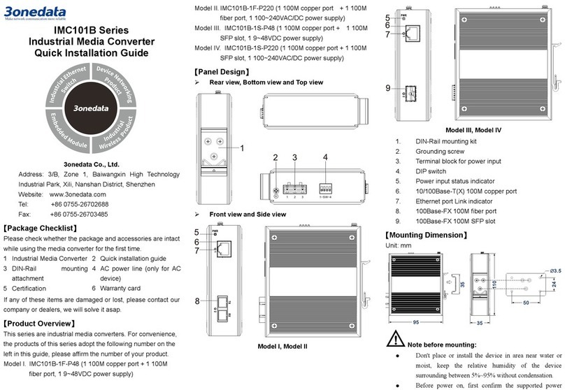
3One data IMC100M Series User manual

IMC100M Series
Industrial Media Converter
Quick Installation Guide
3onedata Co., Ltd.
Address: 3/B, Zone 1, Baiwangxin High Technology
Industrial Park, Xili, Nanshan District, Shenzhen
Website: www.3onedata.com
Tel: +86 0755-26702688
Fax: +86 0755-26703485
【Package Checklist】
Please check whether the package and accessories are intact
while using the media converter for the first time.
1.
Media Converter (with
wiring terminal block)
2. Certification
3. DIN-
Rail mounting
attachment
4. Warranty card
If any of these items are damaged or lost, please contact our
company or dealers, we will solve it ASAP.
【
Product Overview
】
This series product are industrial media converters. Models as
follows:
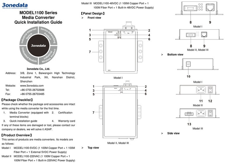
Model I. IMC100M-1T1F (1 100M copper ports + 1 100M fiber
port)
Model II. IMC100M-2T1F (2 100M copper ports + 1 100M fiber
port)
Model III. IMC100M-1GT1GF (1 Gigabit copper port + 1
Gigabit fiber port)
Model IV. IMC100M-1GT1GS (1 Gigabit copper port + 1
Gigabit SFP)
Model V.IMC100M-2GT1GF (2 Gigabit copper ports + 1
Gigabit fiber port)
Model VI. IMC100M-2GT1GS (2 Gigabit copper ports + 1
Gigabit SFP)
【
Panel Design
】
Front View
Model I Model II Model III
Model IV Model V Model VI
Side View
Rear View
Bottom View
Top View
1. Power indicator
2. LFP indicator
3. 100M interface connection status indicator
4. 100Base-FX fiber port
5. 10/100Base-T(X) copper port
6. Gigabit interface connection status indicator
7. 1000Base-X 1×9 fiber port
8. 10/100/1000Base-T(X) copper port
9. 1000Base-X SFP slot indicator
10. 1000Base-X SFP slot
11. DIN-Rail mounting kit
12. DC power terminal block
13. DIP switch
14. Grounding screw (Protective grounding)
15. AC power terminal block
【
Mounting Dimension
】
Unit: mm
Note before mounting:
Don't place or install the device in area near water or
moist, keep the relative humidity of the device
surrounding between 5%~95% without condensation.
Before power on, first confirm the supported power
supply specification to avoid over-voltage damaging the
device.
The device surface temperature is high after running;
please don't directly contact to avoid scalding.
【
DIN-Rail Mounting
】
The product adopts 35mm standard DIN-Rail mounting which
is suitable for most industrial scenes, mounting steps as
follows:
Step 1 Check if the DIN-Rail mounting kit is installed firmly.
Step 2 Insert the bottom of DIN-Rail mounting kit (one side
with spring support) into DIN-Rail, and then insert the
top into DIN-Rail.
Tips:
Insert a little to the bottom, lift upward and then insert
to the top.
Step 3 Check and confirm the product is firmly installed on
DIN-Rail, then mounting ends.
【
Disassembling DIN-Rail
】
Step 1 Device power off.
Step 2 After lift the device upward slightly, first shift out the
top of DIN-Rail mounting kit, and then shift out the
bottom of DIN-Rail, disassembling ends.
Note before powering on:
Power ON operation: First insert the power supply
terminal block into the device power supply interface,
and then plug the power supply plug contact and power
on.
Power OFF operation: First, remove the power plug,
and then remove the wiring section of terminal block.
Please pay attention to the above operation sequence.
【
Power Supply Connection
】
This device provides 3-pin 7.62mm pitch
terminal block, which supports non-polarity and
anti-reverse connection.
Note:
Before connecting to power supply, confirm the power
supply type the product supports.
DC power supply
Voltage range: 24VDC (12~48VDC)
The pin definitions of DC power supply are shown as follows:
PIN
1
2
3
Definition
V+
FG
V-
AC power supply
Power supply value: 220VAC
The pin definitions of AC power supply are shown as follows:
PIN
1
2
3
Definition
N
FG
L
【
DIP Switch Settings
】
Provide 4 pins DIP switch for function settings,
where "ON" is enable valid terminal. The device
needs to be powered on again to change the
status of DIP switch. DIP switches definition as follows:
DIP
ON Status
OFF Status
1
Reserved
2 Enable flow control
function
Disable flow control
function
3
Set the device to remote
mode. PWR indicator
would blink when device
is in remote mode.
Set the device to local
mode. PWR indicator is
on when device is in
local mode.
4
Reserved
【
Checking LED Indicator
】
The device provides LED indicators to monitor the device
working status with a comprehensive simplified
troubleshooting; the function of each LED is described in the
table as below:
LED
Indicate
Description
LED
Indicate
Description
PWR
ON
The power supply
connection is running
normally and the device
is in local mode.
Blinking
The power supply
connection is running
normally and the device
is in remote mode.
OFF PWR is disconnected and
running abnormally
LFP
ON
Fiber port/copper port is
not connected or
connected abnormally.
OFF Fiber port/copper port is
connected normally.
LINK
(1-3/G1-G3/GS)
ON Interface has established
valid network connection
Blinking Interface is in network
active status
OFF
Interface hasn’t
established valid network
connection
【
Specification
】
Panel
100M copper port 100/100Base-T(X) self-adaption
100M fiber port 100Base-FX fiber port
Gigabit copper port 10/100/1000Base-T(X)
self-adaption
Gigabit fiber port 1000Base-X, 1×9 fiber port
Gigabit SFP Slot 1000Base- X, SFP slot
Indicator
Power supply indicator, LFP
indicator, interface connection
indicator
Switch Property
Model I, Model II MAC address: 2K
Packet buffer size: 0.75M
Backplane bandwidth: 0.8G
Model III, Model IV
Model V, Model VI
MAC address: 8K
Packet buffer size: 1M
Backplane bandwidth: 14G
Power Supply
Input power supply DC power supply
12~48VDC
AC power supply 220VAC
DC support nonpolarity
Access terminal block 3-
pin 7.62mm pitch terminal
blocks
Power Consumption
No-load
≤1.47W@24VDC
Full-load
≤1.95W@24VDC
Working Environment
Working temperature
-40~75
℃
Storage temperature
-40~85
℃
Working humidity
5%
~
95% (no condensation)
Protection grade IP40 (corrugated high-strength
metal
)

This manual suits for next models

5

Other 3One data Media Converter manuals
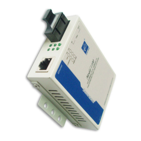
3One data 1100SS User manual

3One data

3One data 1100SS User manual

3One data USB8232I User manual

3One data

3One data USB8232I User manual

3One data IMC101GT Series User manual

3One data

3One data IMC101GT Series User manual

3One data 3012 Series User manual

3One data

3One data 3012 Series User manual

3One data IMC101B Series User manual

3One data

3One data IMC101B Series User manual

3One data 3012SS User manual

3One data

3One data 3012SS User manual

3One data CAN485 User manual

3One data

3One data CAN485 User manual

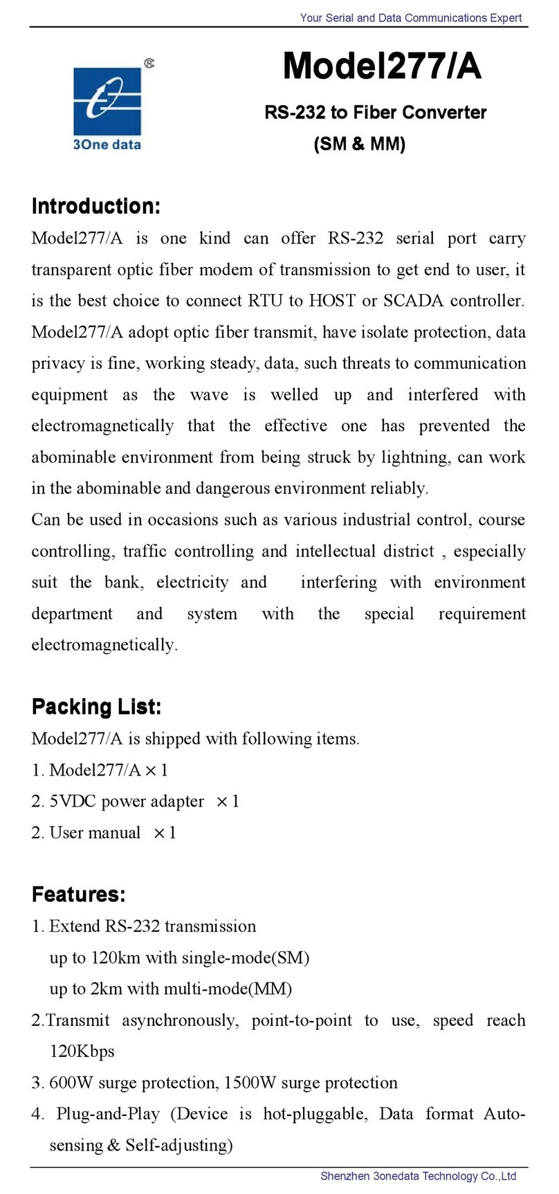
3One data 277/A User manual

3One data

3One data 277/A User manual

3One data USB485 Series User manual

3One data

3One data USB485 Series User manual

3One data 3011 User manual

3One data

3One data 3011 User manual

3One data USB4485 User manual

3One data

3One data USB4485 User manual

3One data Model277 User manual

3One data

3One data Model277 User manual
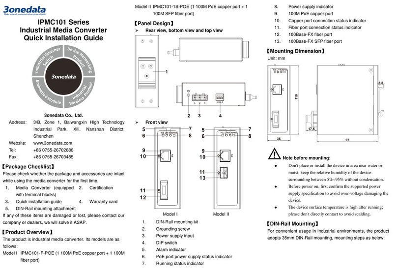
3One data 7210 Series User manual

3One data

3One data 7210 Series User manual
3One data GMI DATABOX USB8485I Series User manual

3One data

3One data GMI DATABOX USB8485I Series User manual

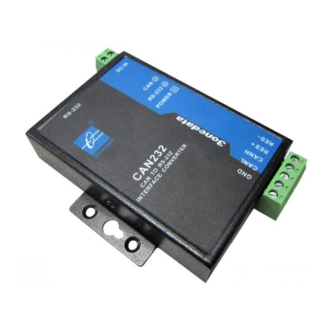
3One data CAN232 User manual

3One data

3One data CAN232 User manual

3One data 1200 User manual

3One data

3One data 1200 User manual

3One data IMC100-2T1F-1D User manual

3One data

3One data IMC100-2T1F-1D User manual

3One data E232 User manual

3One data

3One data E232 User manual

3One data 3010 User manual

3One data

3One data 3010 User manual
3One data PD101G Series User manual

3One data

3One data PD101G Series User manual

3One data 3012 Series User manual

3One data

3One data 3012 Series User manual

3One data 3010 User manual

3One data

3One data 3010 User manual
3One data USB8485I User manual

3One data

3One data USB8485I User manual

3One data SW485GI User manual

3One data

3One data SW485GI User manual

Popular Media Converter manuals by other brands

PXM PX724 user manual

PXM

PXM PX724 user manual

Pentax EPK-P Service manual

Pentax

Pentax EPK-P Service manual

DEVA SmartGen 6.0 Maintenance and operation instruction manual

DEVA

DEVA SmartGen 6.0 Maintenance and operation instruction manual

Converters.TV 912 Operation manual

Converters.TV

Converters.TV 912 Operation manual

HEIDENHAIN LC 2x1 Replacing Instructions

HEIDENHAIN

HEIDENHAIN LC 2x1 Replacing Instructions

GRASS VALLEY 8925EMB-U datasheet

GRASS VALLEY

GRASS VALLEY 8925EMB-U datasheet

ATEN VC812 user manual

ATEN

ATEN VC812 user manual

Crystal Vision Indigo DACA214 user manual

Crystal Vision

Crystal Vision Indigo DACA214 user manual

VOLKTEK NWT-707 user manual

VOLKTEK

VOLKTEK NWT-707 user manual

Fostex 3045 owner's manual

Fostex

Fostex 3045 owner's manual

SEW-Eurodrive EI7 Series manual

SEW-Eurodrive

SEW-Eurodrive EI7 Series manual

Ask Technology ADCN0001M1 user manual

Ask Technology

Ask Technology ADCN0001M1 user manual

Kramer DigiTOOLS 7408 user manual

Kramer

Kramer DigiTOOLS 7408 user manual

Vanner HBA400 Series owner's manual

Vanner

Vanner HBA400 Series owner's manual

Panasonic WJ-GXE100 installation guide

Panasonic

Panasonic WJ-GXE100 installation guide

ADF Web HD67E14-A1 user manual

ADF Web

ADF Web HD67E14-A1 user manual

Linear Technology DC1739B-C Demo Manual

Linear Technology

Linear Technology DC1739B-C Demo Manual

CTS HES-3112-CL-DR SERIES user manual

CTS

CTS HES-3112-CL-DR SERIES user manual

manuals.online logo
manuals.online logoBrands
  • About & Mission
  • Contact us
  • Privacy Policy
  • Terms and Conditions

Copyright 2025 Manuals.Online. All Rights Reserved.