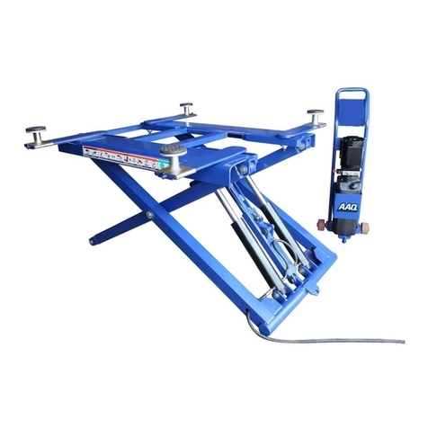
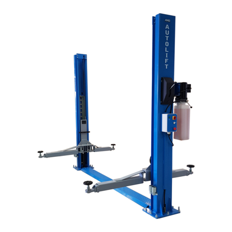
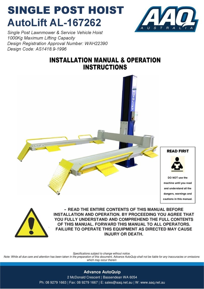
AAQ AutoLift AL-10000T User manual

Advance AutoQuip
2 McDonald Crescent | Bassendean WA 6054
Ph: 08 9279 1663 | Fax: 08 9279 1667 | E: sales@aaq.net.au | W: www.aaq.net.au
-
READ THE ENTIRE CONTENTS OF THIS MANUAL BEFORE
INSTALLATION AND OPERATION. BY PROCEEDING YOU AGREE THAT
YOU FULLY UNDERSTAND AND COMPREHEND THE FULL CONTENTS
OF THIS MANUAL. FORWARD THIS MANUAL TO ALL OPERATORS.
FAILURE TO OPERATE THIS EQUIPMENT AS DIRECTED MAY CAUSE
INJURY OR DEATH.
Specifications subject to change without notice.
Note: While all due care and attention has been taken in the preparation of this document, Advance AutoQuip shall not be liable for any inaccuracies or omissions
which may occur therein
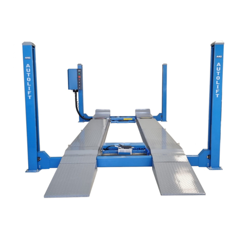
4 POST HOIST
AutoLift AL-10000T
4 Post Vehicle Hoist for Domestic & Light Mechanical Operation
3500Kg Maximum Lifting Capacity
Design Registration Approval Number: WAH21804
Design Code: AS1418.9-1996
INSTALLATION MANUAL & OPERATION
INSTRUCTIONS
READ FIRST
DO NOT use the
machine until you read
and understand all the
dangers, warnings and
cautions in this manual.

CONTENTS
1. Safety 2 - 4
1.1 Introduction
1.2 Symbols
1.3 Intended Use
1.4 Safety Instructions for Commissioning
1.5 Safety Instructions for Operation
1.6 Safety Instructions for Servicing
1.7 Safety Features
1.8 Caution Labeling Exemplify
2. Specifications 5
3. Packing, Transport and Storage 6
3.1 Lifting and handling
3.2 Storage and stacking of packages
3.3 Delivery and check of packages
4. Installation 7 - 18
4.1 Tools Required
4.2 Floor Requirement
4.3 Assembly View/Descriptions of Parts/Floor Plan
4.4 Foundation Dimensions / Specifications
4.4 Power Unit Location
4.5 Raising the Crossbeams
4.6 Powerside Runway Installation
4.7 Offside Runway Installation
4.8 Power Unit Installation & Electrical Connections
4.9 Installing the Locking Device
4.10Anchoring the Columns
4.11Final Assembly
4.12Leveling / Synchronising
4.13Bleeding
5. Operation 19 - 22
5.1 Preparation
5.2 Raising
5.3 Locking
5.4 Vehicle in Raised Position
5.5 Lowering
5.6 Protection Against Unauthorised Usage
5.7 Safety Operating Procedures
5.8 Operation Instructions
6. Maintenance 23 - 28
6.1 Maintenance Schedule
6.2 Maintenance By the Operator
6.3Troubleshooting Guide
7. Explosion Diagrams and Parts List 29 - 34
7.1 Explosion Diagrams
7.2 Parts List
8.Warranty 35
1

1. Safety
1.1 Introduction
Thoroughly read this manual before operating the hoist and comply with the instructions.
Always display the manual in a conspicuous location.
Personal injury and property damage incurred due to non-compliance with these safety instructions are
not covered by the product liability regulations.
1.2 Symbols
1.3 Intended Use
The hoist is designed for the safe lifting of automotive vehicles. Observe the rated load capacity below:
Rated Load Capacity
AutoLift AL-10000T 3500 kg
1.4 Safety Instructions for Commissioning
The hoist may beinstalled and commissioned by authorised service personnel only.
The standard hoist version may not be installed and commissioned in the vicinity of explosives or flammable liquids,
outdoors or in moist rooms (e.g. car wash).
1.5 Safety Instructions for Operation
- Read the operating manual.
-Hoist operation by authorised personnel over 18 years only.
- Always keep the hoist area clean and free of tools, parts, debris etc.
- Before raising and lowering the hoist, always totally secure the vehicle with wheel chocks.
- Make sure the vehicle doors are closed during raising and lowering cycles.
- Closely watch the vehicle and the hoist during raising and lowering cycles.
- Do not allow anyone to stay in hoist area during raising and lowering cycles.
- Never raise a vehicle on the hoist with passengers inside.
- Only use the hoist for its intended purpose.
- Comply with the applicable accident prevention regulations.
- Do not overload the hoist. The rated load capacity is indicated on the hoist nameplate.
- Do not operate the hoist if potential problems have been identified or hoist malfunctions
- Grease and oil spills on runways and working area must be cleaned up immediately.
Failure to comply with instructions could result in personal injury.
Failure to comply with instructions could result in property damage.
Important information
Model No.
2

-To reduce risk of fire, do not operate equipment in the vicinity of open containers of
flammable liquids(gasoline).
-The main switch serves as emergency switch. In case of emergency turnto position 0.
- Protect all parts of the electrical equipment from humidity and moisture.
- Protect the hoist against unauthorised usage by padlocking the main switch.
1.6 Safety Instructions for Servicing
- Maintenance or repair work by authorised service personnel only.
-Turn off and padlock the main switch before doing any maintenance, or repair work.
- Work on pulsegenerators or proximityswitches by authorised service personnel only.
- Work on the electrical equipment by certified electricians only.
- Ensure that ecologically harmful substances are disposed of only in accordance with the
appropriate regulations.
- Do not use high pressure / steam jet cleaners or caustic cleaning agents. Risk of damage!
- Do not replace or override the safety device.
1.7 Safety Features
1.Dead Man´s Type Control
The operator is required to hold the controls in the engaged position to raise or lower the hoist.
2. Equalising System
The hoist is provided with equalising cables to ensure transmission and level movement.
3.Cable Anti-break device
The hoist is equipped with cable anti-break device.
They respond in case of rapid cable broken to prevent sudden lowering movements.
4. Pressure Relief Valve
A pressure relief valve is used to limit the hydraulic working pressure to a maximum of 150 bar.
3

1.8 Caution Labeling
Read operating and safety
manual before using hoist.
Hoist to be used by
trained operator only!
Proper maintenance and
inspection is necessary
for safe operation.
Do not operate a damaged hoist!
Authorised personnel only
in hoist area.
Keep the vehicle in the right
place when lifting.
Clear area if vehicle is in
danger of falling.
Remain clear of hoist when
raising or lowering vehicle.
Do not override self-closing
hoist controls.
Keep feet clear of
hoist while lowering!
Do not stand on hoist while
raising or lowering.
4

Technical Specifications
/LIWLQJ&DSDFLW\ .J
3RZHU8QLW 6LQJOH3KDVH
9$PS
+]
+HLJKWRI&ROXPQV
RYHUDOOKHLJKWRIKRLVW
PP
6L]HRIFROXPQV PP[PP
/LIWLQJKHLJKWLQWRSORFN
SRVLWLRQWRWRSRIUXQZD\
1PP
/HQJWKRI
UXQZD\ PP
:LGWKRIUXQZD\ 5PP
/HQJWKRIDSSURDFKUDPS 560PP
:LGWKEHWZHHQUXQZD\V 60PP
'LVWDQFHWRRXWVLGHRI
ERWKUXQZD\V
1910PP
&OHDUDQFHEHWZHHQFROXPQV 50PP
2YHUDOOOHQJWKSRVWWRSRVW 395PP
2YHUDOOZLGWKZLWKRXWPRWRU 1PP
2YHUDOOZLGWKZLWKPRWRU PP
6KLSSLQJZHLJKW 27.J
6KLSSLQJGLPHQVLRQV 2[4[60PP
SPECIFICATIONS
2.Specifications
5
3975mm
110mm
MIN 130
MAX 1910
560mm
4760mm
2258mm
4395mm
2350mm 2715mm
268mm
268mm
960mm 1910mm 890mm
475mm
4202mm

3. Packing, transport and storage
3.1 Lifting and handling
When loading/unloading or transporting the equipment to the site, be sure to use suitable loading (e.g. cranes,
trucks) and hoisting means. When you want to move the hoist, you need to install the traversing carriages on the
crossbeams and columns by using the special bolt. Dropping the hoist until the columns depart from the earth, you
can move the hoist. Be care no goods on the hoist through out the process.
Be sure also to hoist and transport the components securely so that they cannot drop, taking into consideration
the package’s size, weight and centre of gravity and it’s fragile parts.
3.2 Storage and stacking of packages
Packages must be stored in a covered place, out of direct sunlight and in low humidity, at a temperature
between -10°C and +40°C. Stacking is not recommended: the package’s narrow base, as well as its considerable
weight and size make it difficult and hazardous.
3.3 Delivery and check of packages
When the hoist is delivered, check for possible damages due to transport and storage;
verify that what is specified in the manufacturer’s confirmation of order is included. In case of damage in transit,
the customer must immediately inform the carrier of the problem.
Packages must be opened paying attention not to cause damage to people (keep a safe distance when opening straps)
and parts of the hoist.
6

4. Installation
4.1 Tools Required
- Rotary Hammer Drill or Similar
- 20mm Masonry Bit
- Hammer
- 1 metre Level
- Open-End Wrench Set: 11mm - 28mm
- Socket and Ratchet Set: 11mm - 28mm
- Hex-Key / Allen Wrench Set
- Large Crescent Wrench
- Large Pipe Wrench
- Crow Bar
- Chalk Line
- Medium Flat Screwdriver
- Tape Measure: 8 metre Minimum
- Needle Nose Pliers
4.2 Floor Requirement
Hoist should only be installed on level concrete floors with nomore than 3°of slope and with a minimum of 125 mm
and 25 MPa concrete that has been aged a minimum of 30 days. Confirm that the column baseplate locations you
have marked are a minimum distance of 150mm from any floor seam (see next page). Do not install if floor has cracks
or deterioration that could affect hoist stability. There should be no obstructions in the installation area like floor drains,
under floor piping or electrical conduit that could be damaged or prevent safe hoist installation and secure hoist
anchoring. Check ceiling for beams or heating ducts and walls for protruding structures, etc.
4.3 Assembly View/Descriptions of Parts/Floor Plan
These instructions must be followed to insure proper installation and operation of your hoist. Failure to comply with these
instructions can result in serious bodily harm and void product warranty. Manufacturer will assume no liability for loss
or damage of any kind, expressed or implied resulting from improper installation or use of this product.
Powerside Runway
Approach Ramp
Rear Crossbeam
Power Unit
Offside Runway
Front Crossbeam
Wheel Stop
7

Anchoring the posts
The AutoLift AL-10000T is a portable hoist made to function without being anchored to the floor. The hoist however is
designed to be anchored to the floor and we STRONGLY recommend when lifting a vehicle to anchor the hoist to the floor
using the provided anchor bolts. Anchoring the hoist will make the hoist more stable, but the hoist will not be portable until
the anchors are removed. Your will need a rotary hammer drill with a 19mm carbide masonry drill bit (most rental outlets
have them for rent.)
Your concrete floor must be a least 125mm thick and a minimum of 25MPA. Drill through 16 holes into the
concrete, drilling all the way through the floor. Install the nut and flat washer on the Anchor bolt before putting
them into the holes. Be careful not to move the posts when drilling. One way to avoid this is to drill the holes
and place the bolts in one at a time after the holes are drilled. Re-check the level of each column and place
shims around each anchor and whenever they’re needed. If 12mm or more shim is required, either refinish
concrete or use steel plates and extra long anchor bolts. Tighten the anchor bolts and recheck for level and
plum. Hammer the anchor bolts all the way down. Tighten anchor bolts using a toque wrench to 150 ft. /lbs
(203 N.m)
(DO NOT USE AN IMPACT GUN WHEN TIGHTENING THE ANCHOR BOLTS)
Note: 125mm of embedment is the minimum requirement for reinforced concrete.
Recheck the level of the posts. If the posts are off level at this point, loosen the anchors and use a pry bar to tilt
the posts and shim as needed. Retighten and check again. When satisfied as to level, tighten all the anchor
bolts. THE PROPER OPERATION OF THE HOIST REQUIRES THAT ANY TIME YOU RAISE A VEHICLE
YOU MUST LOWER THE HOIST ONTO THE SAFETY LOCKS.
This is done by raising the vehicle to the desired height and lowering the hoist by pressing the release valve
handle until the hoist stops on the next available lock (check for correct engagement on all locks prior to use)
Note: the power unit is not made to hold the load and may bleed down the locks .
4.4 Foundation Dimensions / Specifications
8

4.5 Column & Cross beam Installation
1. Place a chalk line on the floor according to the floor plan
layout. Pay attention to the power Unit location. Locate and
stand the columns at their respective locations. DO NOT
BOLT Columns down at this time. Use caution to prevent
the Columns from falling over. (See Fig. 4.1)
2. To estimate the shim requirements, place a target on
floor at each Column position and record the readings.
Find the highest of the four locations then find the
difference between each of the remaining Columns. This
difference is the estimated amount of shim thickness that
will be required at each Column. (See Fig. 4.2)
Note: The maximum shim thickness recommended by the
factory is no more than 12mm per Column using shims
and anchors provided with the hoist. A maximum shim
thickness of 50mm is possible by ordering optional shim
plates. Contact your authorised Advance AutoQuip
Distributor for ordering information.
3. Using a forklift or crane, raise the cross beams (making
sure the Plastic Slide Blocks are still in position) and drop
down into the top of the Columns. NOTE: The Sheave
Windows should be positioned inward and adjacent the
Power Unit Column. (See Fig. 4.3)
4. With the Columns standing and the cross beams in
position, install the Safety Ladders. Pass the Ladders
through the Column openings and drop down through the
Slide Block guide slots on the Cross Beams until the
Ladders come to rest on the Base Plates. If bolting, DO
NOT BOLT Columns down at this time. (See Fig. 4.4 - 4.5)
Fig 4.5
Fig 4.4
Fig 4.2
Fig 4.3
Fig 4.1
9

5. The Columns and Cross Beams will now be in position
and spaced properly for the Runways.
6. Install the Column TOP CAPS using the M12 x 2 Hex
Bolts, nuts & washers. Install the nut on each Safety Lad-
der until 12mm of threads are exposed and the Ladder is
raised at least 12mm off of the base of the Column.
NOTE: Raise the Ladder at least 12mm off of the base of
the Column or damage to the hoist will occur. Be sure to
position the cable hole INWARD. (See Fig. 4.6 - 4.7)
1. Before proceeding it will be necessary to first raise
the Cross Beams off the ground to facilitate
Cable routing and final assembly.
2. Manually raise the Cross Beams until the Primary
Safety Locks engage and rest on the lock position second
down from the top of the Ladder or approximately 700mm
off the ground. It is important that the SLACK SAFETY
LOCK IS CLEARED. The Slack Safety Lock must never
rest on the Safety Ladder. To prevent this, manually hold
the Slack Safety in the disengaged position while
lowering the crossbeams ends. (See Fig. 5.1)
3. The Columns and Cross Beams will now be in
position and spaced properly for the Runways. Be very
careful not to disturb the Columns and Cross Beams
at this time as they may tip over causing personal
injury or harm. (See Fig. 5.2)
DANGER!
Be careful not to disturb the Columns and Cross beam
as they may tip over causing personal injury or harm.
IMPORTANT NOTE !
It is important that the SLACK SAFETY LOCK IS
CLEARED. The Slack Safety Lock must never rest on
the Safety Ladder.
Fig 4.7
Fig 5.1
Fig 5.2
Fig 4.6
Slack wire rope lock engaged
Slack wire rope lock disengaged
700mm
4.5 Raising the Crossbeam
10

4.6. Powerside Runway Installation
1. Locate the Powerside Runway easily identified by the
Cylinder and Sheave roller mounting structures welded on the
underside. The Powerside Runway will be positioned on the
side of the hoist where the power unit is installed.
(See Fig. 6.1)
2.Position the Powerside Runway on top of the Cross
Beams with the utility rail towards the center. The Flex
Tube Holes located at the side of the Powerside Runway
should be adjacent to the Power Unit Column. Align the
holes in the Runway with the holes on the Cross Beams
and bolt together the front stop plates using four M12 x
1.75 x 90 Hex Head Bolts and Washers. See notes on
Final Assembly 4.11
4.7 Offside Runway Installation
1. Position the Offside Runway on top of the Cross Beams
with the Utility Rail located inside. Determine the desired
location of the Offside Runway. Align the holes in the
Runway with the desired holes on the Cross Beams and
bolt together the ramp brackets with Hex Head Bolts and
Washers. See notes on Final Assembly 4.11
DANGER !
DO NOT PROCEED with Cable installation or go near
the hoist work area unless visual confirmation is made of
ALL Safety Locks. ALL locks MUST be engaged before
proceeding. Failure to comply with these instructions may
result in severe personal injury or death.
Fig 6.1
Fig 6.4
Fig7.1
11

12

2. Tighten each Nut until there is at least 25mm of
threads protruding through the top of the nut. The Cables
will remain loose until start up and final Cable
adjustments are made. (See Fig. 7.4)
3. After routing the Cables double-check to make sure
all are properly positioned and remain within the grooves
of ALL Sheaves. (See Fig. 7.5 - 7.6)
1. Mount the Power Unit to the Mounting Bracket using
the M8 Hex Head Bolts and Nylock Nuts then fill
the reservoir with 15 litres of 32 grade hydraulic oil.
(See Fig. 8.1)
DANGER!
DO NOT PERFORM ANY MAINTENANCE OR
INSTALLATION OF ANY COMPONENTS WITH OUT
FIRST ENSURING THAT ELECTRICAL POWER HAS
BEEN DISCONNECTED AT THE SOURCE OR PANEL
AND CANNOT BE RE-ENERGIZED UNTIL ALL
MAINTENANCE AND/OR INSTALLATION
PROCEDURES ARE COMPLETED.
DANGER !
ALL WIRING MUST BE PERFORMED
BY A LICENSED ELECTRICIAN.
Fig 8.4
Fig 7.5
Fig 7.6
Fig 7.3
Fig 8.1
4.8 Power Unit Installation & Electrical
Connections
13

IMPORTANT POWER-UNIT
INSTALLATION NOTES
'2127UXQSRZHUXQLWZLWKQRRLO'DPDJHWRSXPSFDQRFFXU
7KHSRZHUXQLWPXVWEHNHSWGU\'DPDJHWRSRZHUXQLWFDXVHGE\ZDWHURURWKHUOLTXLGVVXFKDV
GHWHUJHQWVDFLGHWFLVQRWFRYHUHGXQGHUZDUUDQW\
,PSURSHUHOHFWULFDOKRRNXSFDQGDPDJHPRWRUDQGZLOOQRWEHFRYHUHGXQGHUZDUUDQW\
DANGER!
DO NOT PERFORM ANY MAINTENANCE OR
INSTALLATION OF ANY COMPONENTS WITH OUT
FIRST ENSURING THAT ELECTRICAL POWER HAS
BEEN DISCONNECTED AT THE SOURCE OR PANEL
AND CANNOT BE RE-ENERGISED UNTIL ALL
MAINTENANCE AND/OR INSTALLATION
PROCEDURES ARE COMPLETED.
Diagram 1
Diagram 2
See the detail
to left on how to
wire the Push
Button Switch
Power Unit Motor
Connect either wire from the
Limit Switch to the %OXH Wire
on the top of the Push
Button Switch.
Connect the %URZQ Wire
from the 20 Volt Breaker
Box to the %URZQ Wire 2nd
terminal down on the Switch.
Connect one Motor Wire to the
terPinDO PDrNeG³C´on the 6Zitch
Connect one Power Wire from your
9oOt %reDNer %o[to the center
terminDO mDrNeG³12´ on the 6witch
Connect the other Power Wire
from your 9oOt %reDNer %o[to
the other wire from the Motor.
Fixed Wiring To Motor From The Factory.
%OXH
Push
Button
Switch
Push Button Switch
N.O.
N.C.
Common
Green / GRD
S
%URZQ
4HE¬"ROWN¬7IRE¬IS¬CONNECTED¬STRAIGHT¬TO¬THE¬0OWER¬5NIT
%OXH
4HE¬"LUE¬7IRE¬RUNS¬THROUGH¬THE¬3WITCH¬BEFORE¬CONNECTING¬TO¬THE¬0OWER¬5NIT
The Green Wire is connected to the Grounding Screw inside the Junction Box.
The wiring for your Power Unit and Switches
should only be done by a Certified Electrician!
%URZQ
Quick Disconnect
This will be installed by Electric Lines and
hand mounted to the Power Unit Side Column.
THIS IS YOUR 240 VOLT AC INCOMING POWER SUPPLY OFF OF A 20 AMP BREAKER.
14

1. Feed the front locking lever handle through the power post crossbeam and connect the joining rod to the threaded
tube nuts and lock nuts.
2. Feed the lock lever through the rear crossbeam and connect to the joining rod and lock nuts.
3. Once the locking leaver has been installed and all lock nuts have been tightened, then you can install the rod ends to
the lever bracket. (See Fig. 9.1).
Note: Check all lock nuts are completely tight prior to operation.
4.10 Anchoring the Columns. Optional for the AL-10000T. See notes in section 4.4 Foundation Dimensions.
1. Using the BASE PLATE on each column as a guide, drill each anchor hole completely through the concrete using a rotary
hammer drill and 20mm concrete bit.. ( See Fig. 10.1)
Drill hole
completely
through the
concrete
floor.
Fig. 10.1
4.9 Installing the Locking Device
Fig. 9.1
15

2. After drilling, REMOVE DUST thoroughly from each hole using compressed air and/or bristle brush.
Make certain that the columns remain aligned with the chalk line.
3. Assemble the washers and nuts on the anchors then tap into each hole with a hammer until the washer
rests against the base plate. Be sure that if shimming is required, enough THREADS ARE LEFT EXPOSED.
(See Fig. 10.2)
4. If shimming is required, insert the shims as necessary under the base plate so that when the anchor bolts
are tightened, the columns will be plumb. (See Fig. 10.3)
5. After any necessary shims are installed, tighten each anchor nut to 125-150 ft. lbs. IMPORTANT - If a
anchor bolts do not hold when torqued to required amount, concrete must be replaced.
Saw cut and remove 600mm x 600mm square area under each column base then repour with reinforced
3000 PSI concrete to a depth of six inches minimum, keying new concrete under existing floor.
(See Fig.10.4)
Tap anchor bolts into each
hole with a hammer until the
washer rests against the
baseplate.
Fig. 10.2
Anchor Bolts
Washer
Shims
Nut
Tighten each
anchor nut to
125-150ft. Ibs.
Fig. 10.3
Fig. 10.4
16

4.11 Final Assembly
1. Install the approach ramps on the entry side of the hoist.
2. Install the front wheel stops at the forward side of the hoist using hex bolts, nuts and washers. Torque to 35-45 PSI.
4.12 Levelling / Synchronising
1. Using an engineer’s automatic Level (transit), locate the Level, at a convenient location in the shop that allows an
unobstructed view of all four corners of the runways.
2. Follow the Level manufacturer’s instructions for proper setup of the Level.
Be sure it is ADJUSTED LEVEL in all directions.
3. Raise the hoist approximately 100mm. Then lower hoist until all locking latches are engaged in each column and
the runways are in full down position on locks.
4. Place a Level target on the right/front corner of the runway.
5.Beginning with “A” position, sight the level to the target and mark the number or the graduation on the inch
scale of the target that aligns to the cross hairs of the Level,
6.Next, move the target and place it at point “B” on the runway.
7.Rotate the Level and focus on the target scale.
8. Adjust the adjustment nut on the safety ladder bar at the top of the Column at “B” until the cross hair of the Level
align to reference mark on the target scale.
Runway
Front stop plate
Bolts (M14*85)
Approach
ramp
Stop Plate
Locking leaver assembly
17

9.Repeat steps locating the target assembly at points “C” and “D” and adjusting safety ladders at each
corresponding column until the reference mark on the target scale is on the cross hair of the Level.
The runways are now level at all four points. (See Fig. 12.1)
10.To complete the leveling procedures, TIGHTEN EACH SAFETY LADDER TOP NUT against the bottom of the
Column Top Plate. Torque to 35-45 PSI.
11. Raise the hoist to full height. Listen and watch as the locking latches click in place. SYNCHRONISEBY ADJUSTING
THE CABLES so that all four latches click at the same time. Make necessary adjustments to the cables allowing
COMPENSATION FOR STRETCH.
4.13 Bleeding
1. Hoistmust be fully lowered before changing or adding fluid.
2. Raise and lower hoist six times. The cylinder is self-bleeding. After bleeding system, fluid level in power unit
reservoir may be down. Add more fluid if necessary toraise hoist to full height. It is only necessary toadd fluid
to allow full height raise.
3. To pressure test, run hoistto full rise and run motor for approximately 3-seconds after hoist stops. This will place
pressure on the hydraulic system. Stop and check all fittings and hose connections. Tighten or reseal if required.
Engineer´s Level
(Transit)
Fig. 12.1
Safety locks may not click in at exactly the same time when vehicles are being raised. They should be
close. Be sure that all four corners have passed the SAME safety Ladder Bar slot before lowering hoist on
the safety locks. NEVER lower hoist on different safety lock position or damage to the hoist mayresult.
18

5. Operation
5.1 Preparation
- Position vehicle evenly in the center of each Runway.
- Set parking brake or use wheel chock to hold vehicle in position
- Before raising vehicle, be sure all personnel are clear of the hoist and surrounding area. Pay careful attention
to overhead clearances.
5.2 Raising
1. Turn the main switch to the on position
Hoist is ready for operation.
2.Push and hold UP button on the power unit until hoist reaches desired height.
Hoist stops once button is released.
5.3 Locking
After vehicle is raised to the desired height, Press the lowering lever until the hoist rests on the nearest safety
lock. Do not allow cables to become slack. ALWAYS INSURE SAFETY LOCKS ARE ENGAGED before entering
work area.
During raising and lowering cycles: Closely watch the vehicle and the hoist,
do not allow anyone to stay in hoist area and make sure the vehicle doors are
closed.
UP
Safety locks engaged
ok to proceed
Safety locks not
engaged remain clear
19
Table of contents
Other AAQ Lifting System manuals

AAQ
AAQ SXJS4019A User manual

AAQ
AAQ 167212E User manual

AAQ
AAQ AutoLift 243612 User manual

AAQ
AAQ AL-3060 User manual

AAQ
AAQ AutoLift AL-900DD Technical Document

AAQ
AAQ AutoLift AL-3000AG User manual

AAQ
AAQ AutoLift AL-243156 User manual

AAQ
AAQ AL-6214A Guide

AAQ
AAQ AutoLift AL-8803 User manual

AAQ
AAQ AutoLift AL-9500HD User manual
AAQ
AAQ AL-6254A User manual

AAQ
AAQ AutoLift AL-167261 User manual

AAQ
AAQ AutoLift AL-1132-220 User manual

AAQ
AAQ AutoLift AL-6000S2 User manual

AAQ
AAQ AL-4000A User manual

AAQ
AAQ AutoLift FP-VRC User manual

AAQ
AAQ AutoLift AL-162016 User manual

AAQ
AAQ AutoLift AL-182093 User manual

AAQ
AAQ AutoLift 163027 User manual

AAQ
AAQ AutoLift AL-167262 User manual