Table of contents
Section 1 Introduction.......................................................................3
This manual........................................................................................ 3
Intended audience.............................................................................. 3
Product documentation.......................................................................3
Product documentation set............................................................3
Document revision history............................................................. 4
Related documentation..................................................................4
Symbols and conventions...................................................................4
Symbols.........................................................................................4
Document conventions.................................................................. 5
Section 2 Environmental aspects.....................................................7
Sustainable development................................................................... 7
Disposal of a merging unit.................................................................. 7
Section 3 Unpacking, inspecting and storing................................... 9
Removing transport packaging...........................................................9
Inspecting product and delivery items................................................ 9
Identifying product......................................................................... 9
Checking delivery items.................................................................9
Inspecting product......................................................................... 9
Returning a product damaged in transit...................................... 10
Storing.............................................................................................. 10
Section 4 Mounting.........................................................................11
Checking environmental conditions and mounting space................ 11
Detaching and installing plug-in unit.................................................11
Detaching plug-in unit..................................................................11
Installing plug-in unit....................................................................12
Sealing plug-in unit...................................................................... 15
Securing handle...........................................................................16
Mounting merging unit...................................................................... 17
Required tools............................................................................. 17
Flush mounting merging unit....................................................... 17
Semi-flush mounting merging unit............................................... 20
Semi-flush mounting merging unit inclined..................................23
Rack mounting merging unit........................................................25
Wall mounting merging unit......................................................... 27
Rack mounting merging unit and test switch RTXP into 19”
equipment frame..........................................................................30
Table of contents
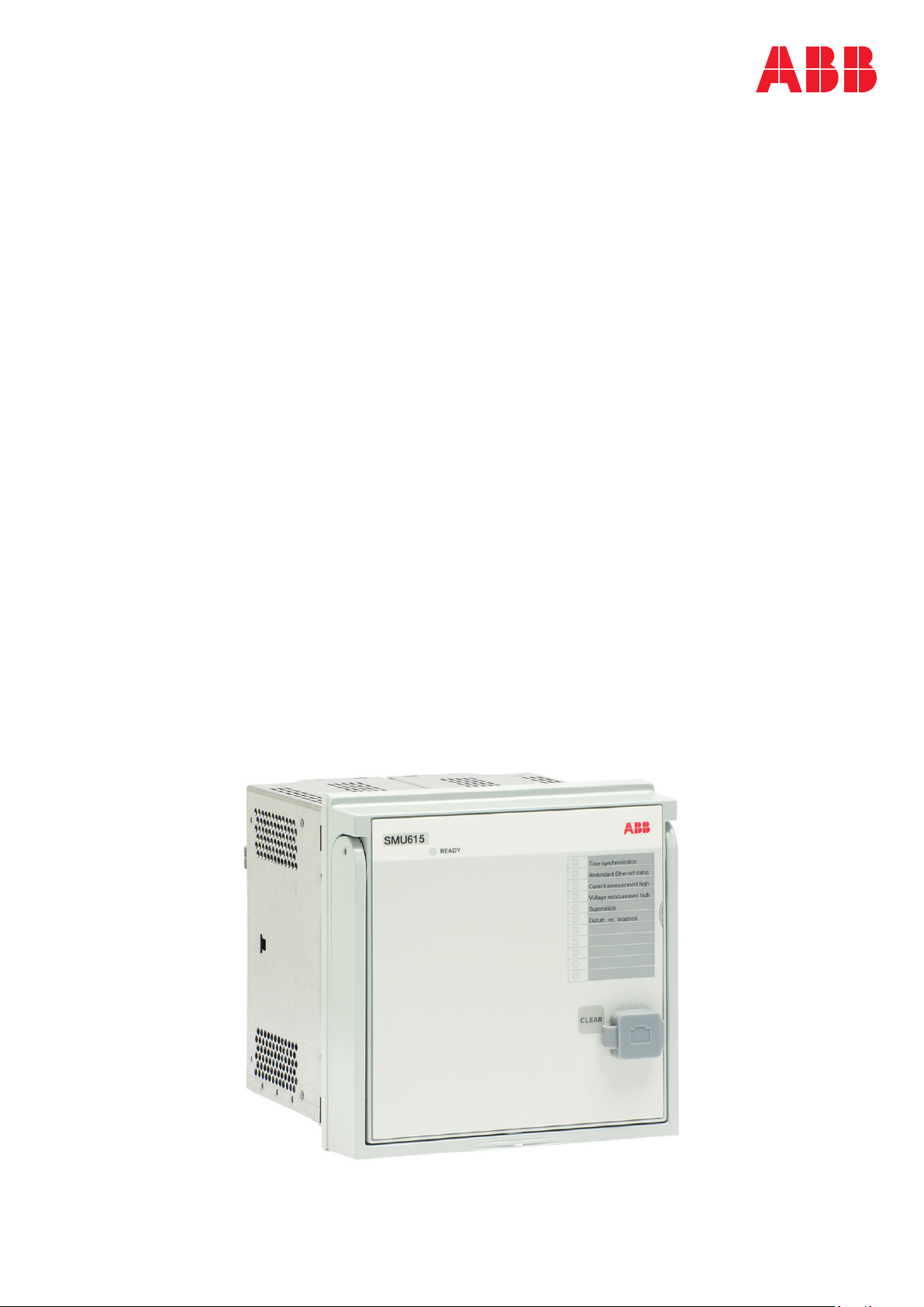
SMU615 1
Installation Manual