manuals.online logo
Brands
  1. Home
  2. •
  3. Brands
  4. •
  5. ABB
  6. •
  7. Accessories
  8. •
  9. ABB Ability Smart Sensor User manual

ABB Ability Smart Sensor User manual

It is important to read these
instructions in their entirety before
installing the ABB Ability™ Smart
Sensor for pumps.
ATTENTION
The Smart Sensor should be installed by technically
qualified personnel. Failure to install the sensor in
compliance with applicable codes and regulations
and according to the manufacturer’s recommen-
dations may result in electrical shock, fire hazard,
unsatisfactory performance or equipment failure,
and may void the sensor warranty.
WARNING
Only qualified individuals who are familiar with
appropriate national codes, local codes and sound
practices should install, repair or modify electric
motors and/or related accessories. Installation
should conform to appropriate codes and practices.
Failure to follow these instructions could result in
serious personal injury, death and/or property damage.
WARNING
Electrical live circuit hazard. Do not touch electrically
live parts or equipment. Disconnect, lock out and tag
out the motor’s power supply before installing or
servicing the sensor.
CAUTION
Surface temperature hazard. The external surface
of an electric motor or the driven pump may reach
temperatures which can cause discomfort, burns
or injury to individuals who come into contact with
the hot surface. For safety reasons the equipment
should be switched off and allowed to cool before
attempting to install the sensor. Equipment surface
temperatures should only be measured with suitable
instruments and not estimated by hand touch or direct
skin contact. Failure to observe this precaution could
result in bodily injury.
CAUTION
Do not replace batteries! Incorrect use of batteries
voids the certifications of the Smart Sensor, such as
safety certifications and IP rating. Dispose of used
sensors according to instructions.
—
INSTALLATION GUIDE
ABB AbilityTM Smart Sensor for pumps
Installation with mounting putty
Installation instruction
Please follow the following instructions for the
installation of ABB AbilityTM Smart Sensors on
pumps.
Mounting position on pumps
1.The sensor must be located on the pump housing
above the drive-end bearing of the pump, closest to
the motor coupling.
2.For best Bluetooth® communication, mount the
sensor with a clear line of sight to any communication
devices to be used: your smartphone or a Bluetooth®
gateway.
3.The mounting orientation must be such that the
A-axis on the sensor housing is parallel to the rota-
ting shaft. If this is not physically possible, the
T-axis must be parallel to the rotating shaft.
Quick start guide
• Step 1: Install the ABB Ability™ Smart Sensor
Platform App
- The Smart Sensor Platform App can be found in
App Store (Apple) and Google Play Store (Android).
- Note: In some countries these stores may not be
accessible. For more information see
www.abb.com/smartsensor.
• Step 2: Register in the ABB Ability™ Smart Sensor
Platform App
- Follow the sign-up link in the app
- Alternatively, sign up on the web portal at
https://smartsensor.abb.com
- Skip this step if you are already registered
• Step 3: Log in to the ABB Ability™ Smart Sensor
Platform App
- Follow the instructions on the screen
• Step 4: Install the ABB AbilityTM Smart Sensor
- Verify that you have the right components and install
the sensor according to the instructions described
in this manual.
• Step 5: Activate the sensor with the ABB Ability™
Smart Sensor Platform App
- Follow the instructions on the screen.
• Step 6: Add the pump in the ABB Ability™ Smart
Sensor Platform App
• Step 7: Activate the sensor’s subscription
- Manually with the ABB Ability™ Smart Sensor
Platform App
- Automatic renewals on ABB Ability MarketplaceTM
• Step 8: Take first measurements and check the
asset condition
- Select the asset and navigate to “Load Measure-
ments”
• Step 9: For more detailed instructions, visit
www.abb.com/smartsensor
2ABB ABILITY SMART SENSOR FOR PUMPS INSTALLATION GUIDE FOR INSTALLATION WITH MOUNTING PUTTY
Supported pumps
• Pump type: Single-stage, overhung centrifugal pump
• Impeller type: Single-channel or vortex
• Fluid type: Water or wastewater
• Min. recommended no. of impeller blades: bMIN = 3
• Speed control: fixed / direct-online (DOL) or variab-
le-speed
• Maximum blade-pass frequency (BPF): 6000 RPM
- Rotating speed ω
- No. of blades b
BPF = ωx b < 6000 RPM
• Power / size: shaft height from 150 mm to 450 mm
Items needed
The ABB Ability™ Smart Sensor kit includes:
• 1 LoctiteTM 3463 mounting putty (1 tube)
• 2 Receiving mount
• 3 Mounting bracket
• 4 Phillips head screws (2 qty) M4-0.7 x 10 mm
• 5 Tapered hex Drive Flat Head Screw (1 qty)
1/4” x 5/8” (UNF 28)
• 6 ABB AbilityTM Smart Sensor for pumps
1
23
6
5
4
4
Step 1
Use solvent (i.e. paint thinner or acetone) to remove
debris and oils from mounting surface.
Installation steps
Additional items needed, but not included in the kit:
• Degreasing agent
• Clean shop rag
• Rubber gloves
• Mechanical abrasive pad (e.g. sandpaper)
• Allen wrench (4 mm or 5/32”)
• Small Phillips head screw driver
• Leveling tool
• Cutting tool
• LoctiteTM Blue Threadlocker
Safety and technical information on LoctiteTM 3463
adhesive putty: http://www.henkel.com
Step 2
Use sandpaper or similar abrasive material to remove
paint from mounting surface. Repeat step 1.
WARNING
Direct skin exposure to solvents and/or threadlocker
could cause discomfort or injury, including, but not
limited to, burning or skin irritation. Use appropriate
protective gloves and goggles when following these
instructions.
3
Use the receiving mount included in the kit.
Step 4
Squeeze, knead, twist and roll putty until it has a uni-
form, homogeneous color according to manufacturer’s
instructions. This should take 5–10 minutes.
Step 3
Remove putty from tube and cut out between 1/4 and
1/3 of the putty for installation of receiving mount.
CAUTION: REVIEW AND FOLLOW ALL MANUFACTUR-
ER’S INSTRUCTIONS AND SAFETY PRECAUTIONS
WHEN USING SOLVENTS.
CAUTION: REVIEW AND FOLLOW ALL MANUFACTUR-
ER’S INSTRUCTIONS AND SAFETY PRECAUTIONS
WHEN USING ADHESIVE PUTTY.
9AKK107416 REV D EN 06-2020
—
For questions, feedback and support, please contact:
Product information
www.abb.com/smartsensor
Support
[email protected]
Subscriptions
https://eu.marketplace.ability.abb/
NOTE: After commissioning, the sensor has a two-
month trial period with full functionality. After the
trial period, the usage can be continued by activa-
ting a subscription acquired from a local ABB sales
unit or from ABB Ability MarketplaceTM. Please check
with your local ABB partner if the ABB Ability Market-
placeTM is available in your region.
Next step
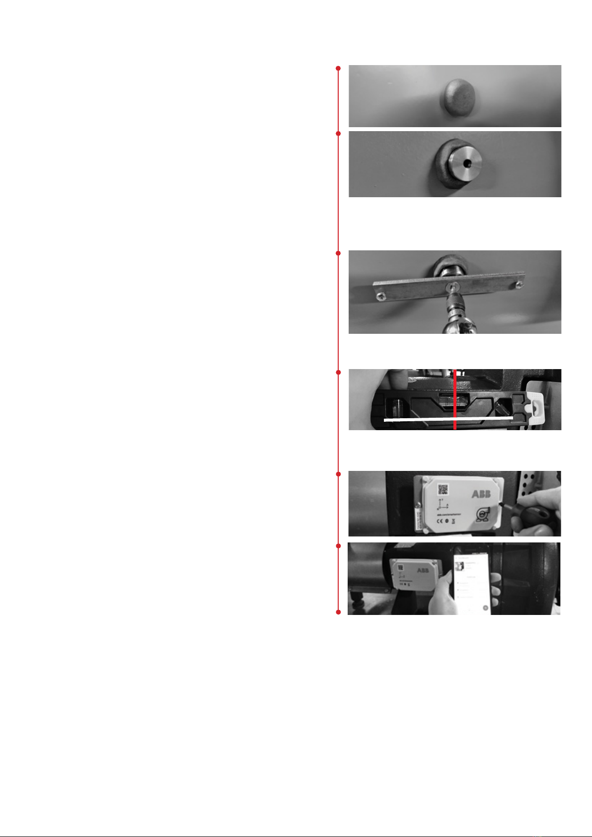
Digitally connect Smart Sensor using the ABB Ability™
Smart Sensor Platform app. Log on using your ABB
credentials and follow the prompts to connect.
—
We reserve the right to make technical
changes or modify the contents of this
document without prior notice. With re-
gard to purchase orders, the agreed par-
ticulars shall prevail. ABB Ltd does not ac-
cept any responsibility whatsoever for
potential errors or possible lack of infor-
mation in this document.
We reserve all rights in this document and
in the subject matter and illustrations con-
tained therein. Any reproduction, disclo-
sure to third parties or utilization of its
contents – in whole or in parts – is forbidden
without prior written consent of ABB Ltd.
Copyright© 2020 ABB
All rights reserved
Step 9
Use two Phillips head screws to securely fasten the
ABB Ability™ Smart Sensor to mounting bracket.
4
Step 6
Immediately after applying putty, insert receiving
mount into center of putty, pressing firmly. Form any
excess putty around the sides of the mounting piece.
Step 5
Firmly apply putty to the clean housing surface or,
alternatively, wrap the putty around the end of the
receiving mount before attaching to the surface.
The putty should be approx. 1.25 inch (3 cm) wide.
Step 7
Secure bracket to receiving mount using the hex head
screw. Apply Loctite™ or equivalent threadlocker to the
screw threads, ensuring that the screw head is locked
1 mm above chamfer for the best heat and vibration
transmission.
Step 8
Use a level to verify the alignment. The axial direction
(white line) must be parallel to the pump shaft. The
tangential axis (red line) should be at a right angle to
the axial line, on a plane tangential to the housing.
The radial direction (black line) points towards the
center line of the shaft. If this is not possible, the
T-axis must be parallel to the rotating shaft.
CAUTION: ALLOW SUFFICIENT TIME FOR PUTTY TO
HARDEN BEFORE PROCEEDING. CURING TIME DE-
PENDS ON SURFACE AND AMBIENT TEMPERATURES.
TYPICAL CURING TIME IS 10 MINUTES, BUT THIS CAN
TAKE LONGER IN COLD ENVIRONMENTS.
CAUTION: REVIEW AND FOLLOW ALL MANUFACTURER’S
INSTRUCTIONS AND SAFETY PRECAUTIONS WHEN
USING THREADLOCKER.
T
A
R

Other manuals for Ability Smart Sensor

5

Other ABB Accessories manuals

ABB i-bus 6115-24-500 User manual

ABB

ABB i-bus 6115-24-500 User manual

ABB free@home 180 flex 62762-WL-500 Series User manual

ABB

ABB free@home 180 flex 62762-WL-500 Series User manual

ABB 2CSYD0102B Guide

ABB

ABB 2CSYD0102B Guide

ABB AP201 User manual

ABB

ABB AP201 User manual

ABB LM80 User manual

ABB

ABB LM80 User manual

ABB HS/S4.2.1 User manual

ABB

ABB HS/S4.2.1 User manual

ABB SmarTac Instructions for use

ABB

ABB SmarTac Instructions for use

ABB ADS420 User manual

ABB

ABB ADS420 User manual

ABB Cylon FBXi User manual

ABB

ABB Cylon FBXi User manual

ABB ABB-free@home WBI-S-1-xx-WL Series User manual

ABB

ABB ABB-free@home WBI-S-1-xx-WL Series User manual

ABB AquaMaster4 User manual

ABB

ABB AquaMaster4 User manual

ABB AP300 User manual

ABB

ABB AP300 User manual

ABB Ability User manual

ABB

ABB Ability User manual

ABB Endura AZ40 User manual

ABB

ABB Endura AZ40 User manual

ABB NIESSEN 8131 User manual

ABB

ABB NIESSEN 8131 User manual

ABB TOTALFLOW LevelMaster Series User guide

ABB

ABB TOTALFLOW LevelMaster Series User guide

ABB SCC-C User manual

ABB

ABB SCC-C User manual

ABB ClimaECO SBS/Ux.0.1 Series User manual

ABB

ABB ClimaECO SBS/Ux.0.1 Series User manual

ABB AquaProbe FEA100 User manual

ABB

ABB AquaProbe FEA100 User manual

ABB 4690 Series User manual

ABB

ABB 4690 Series User manual

ABB Eden DYN User manual

ABB

ABB Eden DYN User manual

ABB LevelMaster 7100 User manual

ABB

ABB LevelMaster 7100 User manual

ABB Ability Smart Sensor Instruction sheet

ABB

ABB Ability Smart Sensor Instruction sheet

ABB AP200 Series User manual

ABB

ABB AP200 Series User manual

Popular Accessories manuals by other brands

Vanderbilt IMKW6-10 Installation instruction

Vanderbilt

Vanderbilt IMKW6-10 Installation instruction

Imetec SCALDALETTO Instructions for use

Imetec

Imetec SCALDALETTO Instructions for use

Invacare Infinity LoBack Support Owner's operator and maintenance manual

Invacare

Invacare Infinity LoBack Support Owner's operator and maintenance manual

Sentry W9000 Series Installation, operation & maintenance manual

Sentry

Sentry W9000 Series Installation, operation & maintenance manual

ZooZ ZSE30 user manual

ZooZ

ZooZ ZSE30 user manual

Climax Technology SVGS-5 manual

Climax Technology

Climax Technology SVGS-5 manual

Leedarson 7AA-SS-VE-A0 quick start guide

Leedarson

Leedarson 7AA-SS-VE-A0 quick start guide

Philips PR3110 user manual

Philips

Philips PR3110 user manual

Silver Cross Ride-on Board manual

Silver Cross

Silver Cross Ride-on Board manual

BEA LZR-WIDESCAN manual

BEA

BEA LZR-WIDESCAN manual

Knightsbridge TPB14SLED Installation & maintenance manual

Knightsbridge

Knightsbridge TPB14SLED Installation & maintenance manual

Grandview CN-MRxx instruction manual

Grandview

Grandview CN-MRxx instruction manual

Philips DLA71026 brochure

Philips

Philips DLA71026 brochure

Vaisala Thunderstorm LS7002 Brochure & specs

Vaisala

Vaisala Thunderstorm LS7002 Brochure & specs

Evolveo Porta U2 quick start guide

Evolveo

Evolveo Porta U2 quick start guide

Honeywell 4AV15F installation instructions

Honeywell

Honeywell 4AV15F installation instructions

Tecsis P3307 operating instructions

Tecsis

Tecsis P3307 operating instructions

GSi 21' Diameter Gamma Assembly instructions

GSi

GSi 21' Diameter Gamma Assembly instructions

manuals.online logo
manuals.online logoBrands
  • About & Mission
  • Contact us
  • Privacy Policy
  • Terms and Conditions

Copyright 2025 Manuals.Online. All Rights Reserved.