ABB 2769522-C Product manual

1ZSC000563-ACD EN, REV. A, 2019-06-25
Test adapter
Installation and maintenance guide

The information contained in this document may be subject to change without prior warning and should not be considered
as binding on ABB AB’s behalf. ABB AB accepts no liability for any errors that may appear in this document. ABB AB is
not liable for any damage resulting from the incorrect interpretation of this document. This document, or parts thereof, may
not be reproduced or copied without ABB AB’s consent. It may not be distributed to others, or used by unauthorized
parties. Any breaches to the above will be penalized with the support of applicable laws.

Installation and maintenance guide
1ZSC000563-ACD EN, REV. A, 2019-06-25
3
Contents
1 Safety 5
1.1 Levels of safety risks ................................................................................................................................................................... 5
1.2 Hazardous working situations ..................................................................................................................................................... 6
1.3 Safety precautions....................................................................................................................................................................... 6
2 Product description 7
2.1 Design ......................................................................................................................................................................................... 7
2.2 Usage .......................................................................................................................................................................................... 9
2.3 Description and limitations of the tap .......................................................................................................................................... 9
3 Delivery 11
3.1 Incoming inspection..................................................................................................................................................................... 11
3.2 Transportation ............................................................................................................................................................................. 11
3.3 Storage........................................................................................................................................................................................ 11
4 Installation 13
4.1 Tools ............................................................................................................................................................................................ 13
4.2 Consumables .............................................................................................................................................................................. 13
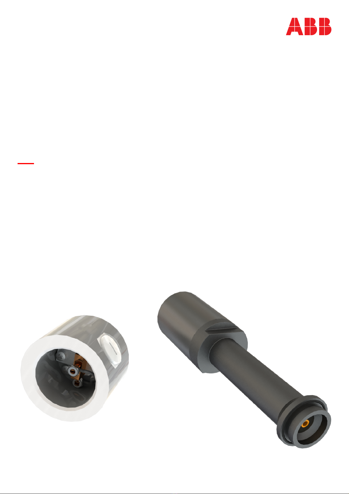
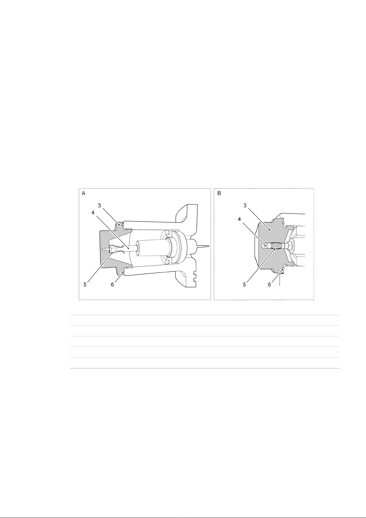
4.3 Installation of the test adapter, 1ZSC003881-AAC...................................................................................................................... 14
4.4 Installation of electrical circuits, 1ZSC003881-AAC ....................................................................................................................16
4.5 Installation of the test adapter, 2769522-C.................................................................................................................................. 19
4.6 Installation of electrical circuits, 2769522-C ................................................................................................................................ 22
5 Commissioning 25
5.1 Output error sources ................................................................................................................................................................... 25
5.2 Insulation test .............................................................................................................................................................................. 25
6 Disposal and environmental information 27
6.1 Overview ..................................................................................................................................................................................... 27
6.2 Disposal and recycling ................................................................................................................................................................ 27
7 References 29
7.1 Summary ..................................................................................................................................................................................... 29

4Installation and maintenance guide
1ZSC000563-ACD EN, REV. A, 2019-06-25

Installation and maintenance guide
1ZSC000563-ACD EN, REV. A, 2019-06-25
5
1 Safety
1.1 Levels of safety risks
Throughout the manual, various types of safety risks are indicated. The most serious level on this scale
provides a warning about serious personal injury or possible death, or major damage to a product, if the
instructions are not observed.
Symbols and their meanings
The following describes the symbols that appear in the manual, along with their meaning.
DANGER!
The yellow, filled warning triangle warns that an accident will occur if the instructions are not
complied with and that it will result in serious personal injury or death and/or major damage to the
product.
It is used, for example, to warn of such dangers as: contact with high voltage, explosion or fire
risk, risk for toxic gases, risk of crushing, impacts, falls from high places, etc.
CAUTION!
The round warning symbol warns that an accident could occur if the instructions are not observed,
and that this could result in personal injury and/or damage to the product.
It is also used to warn of risks that entail burns, eye or skin injuries, impaired hearing, crushing or
slipping injuries, tripping, impacts, falls from high places, etc.
In addition, it is used to warn of functional requirements when assembling or removing equipment
where there is a risk of damage to the product or downtime.
NOTE!
The comment symbol identifies important information and conditions. Also used to indicate any
danger that could lead to property damage.
Torque
The torque symbol indicates tightening torque.

6Installation and maintenance guide
1ZSC000563-ACD EN, REV. A, 2019-06-25
1.2 Hazardous working situations
Hazard Action
Working close to high voltage. Disconnect all plant power. Ground all objects at the workplace.
If work must be done close to live plant components, make sure that
the safety distance is in compliance with the applicable safety
regulations.
Working on ladders and platforms. Work must be done in accordance with the applicable safety
regulations.
Do not use ladders or platforms in poor weather conditions.
Working with heavy objects. Do not walk under lifted objects.
Make sure that heavy objects are stable before starting work.
1.3 Safety precautions
Precaution Action
Transformer oil Collect used transformer oil in drums.
Transformer oil is dangerous. Fumes from hot oil can cause irritation
to the respiratory organs and the eyes. Long and repeated contact
with transformer oil can cause damage to your skin.
SF6gas SF6gas must be recycled and never released into the atmosphere.
Waste and cleaning up Clean up liquid waste with an adsorbent. Treat waste as hazardous
to the environment.
Fire Extinguish fires with powder, foam or carbon dioxide.

Installation and maintenance guide
1ZSC000563-ACD EN, REV. A, 2019-06-25
7
2 Product description
2.1 Design
Overview
The test adapter from ABB Components can permanently connect the tap on the bushing to measuring
equipment, for monitoring of the bushing during service.
All transformer bushings and some wall bushings that are manufactured by ABB Components, are
capacitance-graded bushings that are equipped with a voltage tap or test tap.
Tap types
G000738
A Large tap. Voltage tap (two connected layers), or test tap (one connected layer).
B Small tap. Test tap (one connected layer).
3 Cover
4 Stud
5 Grounding spring
6 O-ring

8Installation and maintenance guide
1ZSC000563-ACD EN, REV. A, 2019-06-25
Test adapter, 2769522-C
G000745
1 Terminal box
2 Plug
3 Cover*
4 Nut
* This cover is installed on the bushing on delivery from ABB.
Test adapter, 1ZSC003881-AAC
G000778
1 Terminal cover
2 Extension
3 Plug

Installation and maintenance guide
1ZSC000563-ACD EN, REV. A, 2019-06-25
9
2.2 Usage
Overview
Use the test adapter only as described in this installation and maintenance guide, and obey the limitations of
the test adapter. Refer to Description and limitations of the tap, page 9.
Grounding
The tap is not self grounding, and must always be grounded or connected to an external impedance. Because
C2usually is relatively small, the test tap must never be open-circuited when the bushing is energized.
If the tap is not grounded when the bushing is energized, failure of the bushing will occur.
CAUTION!
Do not energize the bushing without a test adapter or the cover installed. The bushing is grounded
through the cover to prevent damage to the bushing.
2.3 Description and limitations of the tap
Overview
The values of impedance for the main insulation and the tap are unique to every bushing. Refer to the rating
plate on the bushing or to the bushing installation and maintenance guide.
The value of the capacitance C2depends on the design of the bushing and on its installation, and can thus
vary more or less. The capacitance C2should be measured after installation of the bushing, to get an accurate
value.
CAUTION!
Do not connect a circuit that overloads test adapter. This will lead to partial discharge in the
bushing, which will cause damage to the bushing.
NOTE!
The test adapter limits the amount of power that can be passed through the tap, despite a higher
capacity of the tap.
G000748
* The connected circuit is the equipment and cables that are connected to the test adapter.

10 Installation and maintenance guide
1ZSC000563-ACD EN, REV. A, 2019-06-25
Limitation of the connected circuit
Maximum allowed voltage, U2: At service voltage: 110 V
At lightning impulse: 200 V
Maximum inductive and/or resistive loads, Z: ωL = 100 mΩ
R = 100 mΩ
Unit Definition
C1Capacitance 1 in condenser core, [F]
Refer to the test report for the bushing.
C2Capacitance 2 in condenser core, [F]
Refer to the test report for the bushing when it was
installed on the transformer.
U2Tap voltage, [V]
U2max The maximum service voltage, [V]
U1Voltage between outer terminal and earth, [V]
R Resistance, [Ω]
Z Impedance, [Ω]
ω Angular velocity for AC voltage [rad/s]
L Inductance, [H]
ωL Inductive reactance, [Ω]
Z Inductive and/or resistive loads, [Ω]

Installation and maintenance guide
1ZSC000563-ACD EN, REV. A, 2019-06-25
11
3 Delivery
3.1 Incoming inspection
Make sure that all items have been delivered, refer to the packing list.
Carefully inspect the parts for shipping damage.
3.2 Transportation
Keep the test adapter in the original packaging during transportation.
3.3 Storage
Keep the test adapter in the original packaging until installation.
The test adapter must be stored indoors, in a controlled temperature with low humidity.

12 Installation and maintenance guide
1ZSC000563-ACD EN, REV. A, 2019-06-25

Installation and maintenance guide
1ZSC000563-ACD EN, REV. A, 2019-06-25
13
4 Installation
4.1 Tools
Tool Part number Note
Torque wrench -
Crosshead screwdrivers - Phillips type and Pozidriv type.
4.2 Consumables
Item Brand Part number Note
Mobilgrease 28 MOBIL 11714014-407 Lubricates and protects
metals against corrosion.
Protects rubber. Does not
react with transformer oil.

14 Installation and maintenance guide
1ZSC000563-ACD EN, REV. A, 2019-06-25
4.3 Installation of the test adapter, 1ZSC003881-AAC
Overview
G006815
1 Cover
4 Test adapter, 1ZSC003881-AAC
DANGER!
Risk of death to personnel!
Make sure that the bushing is de-energized and out of service.
Make sure that the high-voltage parts are visibly grounded, before removing the cover on the tap.
CAUTION!
Do not energize the bushing without a test adapter (4) or the cover (1) installed. The bushing is
grounded through the test adapter (4) or cover (1) and this prevents damage to the bushing.
Procedure
1. Remove the cover (1).
G000773

Installation and maintenance guide
1ZSC000563-ACD EN, REV. A, 2019-06-25
15
2. Remove the protective cap (6).
G000774
3. Apply Mobilgrease 28 to the O-ring (2) and and
the threads of the test adapter (4).
G000779
4. Put the O-ring (2) in the groove in the test adapter (4).
5. Install the test adapter (4), and tighten it.
G000781
Torque
15 Nm
End of instruction

16 Installation and maintenance guide
1ZSC000563-ACD EN, REV. A, 2019-06-25
4.4 Installation of electrical circuits, 1ZSC003881-AAC
Procedure
1. Remove the terminal cover (5), and the O-ring (7).
G002953
2. Apply Mobilgrease 28 to the O-ring (7) and put it
in the groove.
G006827
3. Remove the grounding cable (6).
G003137

Installation and maintenance guide
1ZSC000563-ACD EN, REV. A, 2019-06-25
17
4. Remove the plug (11).
G006816
5. Put the signal cable through the cable gland (9).
CAUTION!
Make sure that the seal (8) has a
correct seal against the signal cable.
An incorrect seal will cause water to
leak into the terminal cover.
NOTE!
If the bushing is used outdoors: the
cable gland must be of
IP67 classification or better, and have a
rubber seal (8).
NOTE!
The cable gland must have
PR 16 threads.
G006820
6. Install the cable gland (9) to the terminal
cover (5).
G006419

18 Installation and maintenance guide
1ZSC000563-ACD EN, REV. A, 2019-06-25
7. Install the signal cable for the measuring
equipment, refer to the instructions from the
manufacturer.
CAUTION!
Use a signal cable of sufficient size for
the amperage and voltage. Make sure
that the signal cable is rated for
outdoor use, and that it has the correct
shielding for this application.
G005034
8. Make sure that the measuring equipment receives signals correctly.
9. Apply Mobilgrease 28 to the threads of the the
terminal cover (5), and install it.
CAUTION!
Make sure that the terminal cover seals
correctly. An incorrect seal will cause
water to leak into the test adapter.
G006819
Torque
Tighten with your hand.
10. Make sure that the flexible rubber seal (8) has a
correct seal against the signal cable.
CAUTION!
An incorrect seal will cause water to
leak into the test adapter.
G006831
End of instruction

Installation and maintenance guide
1ZSC000563-ACD EN, REV. A, 2019-06-25
19
4.5 Installation of the test adapter, 2769522-C
Overview
G006821
1 Cover
8 Test adapter, 2769522-C
DANGER!
Risk of death to personnel!
Make sure that the bushing is de-energized and out of service.
Make sure that the high-voltage parts are visibly grounded, before removing the cover on the tap.
CAUTION!
Do not energize the bushing without the cover (1) installed. The bushing is grounded through the
cover and this prevents damage to the bushing.
Procedure
1. Remove the cover (1).
G000771

20 Installation and maintenance guide
1ZSC000563-ACD EN, REV. A, 2019-06-25
2. With the screws (5), adjust the nut (2) to a
distance of 1,5 mm (±0,5 mm) from the terminal
box (4).
G005030
3. Apply Mobilgrease 28 to the O-ring (3), and put it
in the groove (7) in the terminal box.
CAUTION!
Do not remove the plug (11) until the
measuring circuits are installed.
Moisture will enter the terminal box.
G001914
4. Install the test adapter (8).
G001917
This manual suits for next models
1
Table of contents
Other ABB Adapter manuals

ABB
ABB SPA-ZC 402 Guide

ABB
ABB FENA-21 Installation manual

ABB
ABB RETA-01 User manual

ABB
ABB Tina 3A User manual

ABB
ABB FPBA-01 PROFIBUS DP User manual

ABB
ABB FBIP-21 BACnet/IP Installation manual

ABB
ABB SPA-ZC 400 User manual

ABB
ABB RS485 Modbus adapter User manual

ABB
ABB SPA-ZC 400 Guide

ABB
ABB Tina 2B User manual

ABB
ABB Tina 10B User manual

ABB
ABB AC 31 Installation and operating instructions

ABB
ABB FBIP-21 BACnet/IP User manual

ABB
ABB Unifix AD 1STQ003941B0000 manual

ABB
ABB FPBA-01 PROFIBUS DP Installation manual

ABB
ABB FieldKey NHU200 User manual

ABB
ABB SPA-ZC 402 Guide

ABB
ABB FENA-01 User manual

ABB
ABB CEM 05100 User manual

ABB
ABB Tina 3A/Aps User manual