PREFACE............................................................................................................................................................3
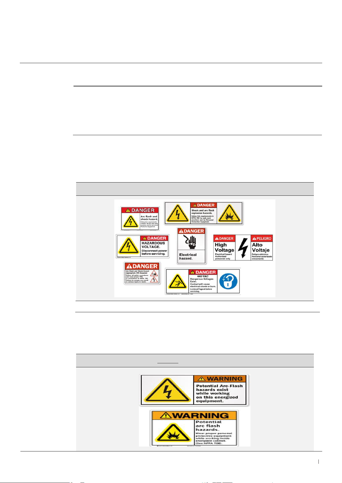
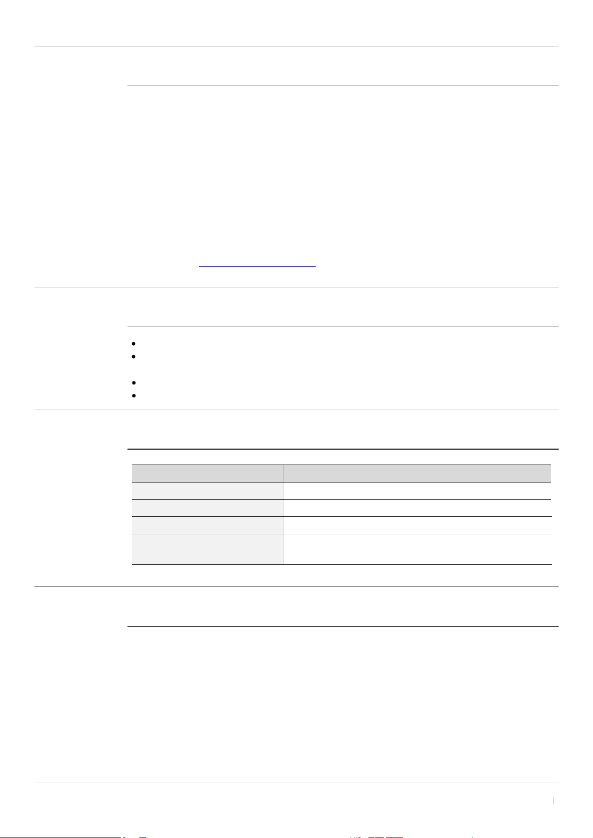
....................................................................................................................................................................31- Hazards
...................................................................................................................................................................52- Warranty
......................................................................................................................................53- Trademarks and patents
................................................................................................................................................................54- Standards
........................................................................................................................................55- Document Conventions
.............................................................................................................................................66- Related Publications
.............................................................................................................................................67- Service and Support
..................................................................................................................68- Estimated Time to Complete Tasks
........................................................................................................................................................79- Product Specs
.......................................................................................................................................9HISTORY AND TYPES
......................................................................................................................................................910- History of AKD
.........................................................................................................................11AKD-6, RETROFILL BREAKER
.......................................................................................................................................1111- AKD-6, Breaker Models
............................................................................................................................1212- AKD-6, Mechanical drawings
...................................................................................................................................14AKD-6 COMPARTMENT
.........................................................................................................................................................1413- Interior View
..................................................................................................16MODIFY AKD-6 , SWITCHGEAR COMPARTMENT
.........................................................................................................................1614- Cut Power to AKD-6: Switchgear
............................................................................................................................1615- Rack Out AKD-6, Legacy/Existing CB
................................................................................................1616- Check, Clean, Grease AKD-6, Compartment
....................................................................................................................................17UNPACK CIRCUIT BREAKER
...................................................................................................................................................................1817- Quality
...............................................................................................................................................1818- Information Label
.............................................................................................................1819- Product and Catalog Serial Numbers
..................................................................................................1820- Remove Circuit Breaker from Container
...............................................................................................................................19STORE CIRCUIT BREAKER
.........................................................................................................................20CHECK BEFORE INSTALLING.
.......................................................................................................................20CLEAN AND GREASE BREAKER
........................................................................................................................................21MODIFY RETROFILL
......................................................................................................22PREPARE SWITCHGEAR COMPARTMENT.
......................................................................................24INSTALLING AKD-6 RETROFILL CIRCUIT BREAKER
................................................................................................................2421- Breaker Installation Overview.
..................................................................................................2522- For AKR 30/50/T50 AKD-6 Retrofill Breaker
...........................................................................................26INSTALL OR INSERT AKD-6 RETROFILL
......................................................................................29INSTALLATION OF AKD-6 AKR 75/100 Retrofill Breaker
AKD-6 - INSTALL ACCESSORIES................................................................................................................................30
.........................................................................................................3023- AKD-6, Secondary Disconnects, Bullets
.................................................................................3624- 19 pin Programmer Secondary Disconnect (Breaker)
...................................................3925- Install 19 Pin Programmer Secondary Disconnect (Compartment)
...........................................................................................................4126- AKD-6: Position Switch Actuator
................................................................................................................................42DOOR INTERLOCK SYSTEM
.........................................................44INSTALLING NEUTRAL DISCONNECT ASSEMBLY(BREAKER SIDE)
.............45AKR 100 - 4000A , FAN CONTROL UNIT WIRING & TRIP UNIT PROGRAMMING INSTRUCTIONS
.....................................................................................47CONFIGURING EKIP TOUCH, HI TOUCH TRIP UNIT
.....................................................................................................................................4727- Connecting Ekip Touch
...........................................................................4828- Synchronizing 2K-1 signalling module with the trip unit
....................................................................................................................4929- Configuring threshould currents
................................................................................................5030- Programing 2K-1 signaling contacts output
............................................................................................................................5131- Contact readiness Auto Test
©2022 Emax 2 Retrofill Circuit Breakers 800A-4000A 2
2TSA451014P0000 Rev-B