Air
Circuit
Breakers
Type AK-1-15 and AK-1-25 GEH-1807
TROUBLE
SHOOTING
TROUBLE
CAUSE
REMEDY
Failure
to Close Latch
return
spring too weak
or
broken. Replace spring.
and Latch Hardened
or
gummy lubrication on Clean bearing and latch
bearing and latch
surfaces. surfaces.
Closing solenoid burned out. Replace solenoid coil.
Solenoid control device not functioning Re-adjust
or
replace
device.
proper
ly•
BASiC BREAKER
·COMPON.ENTS
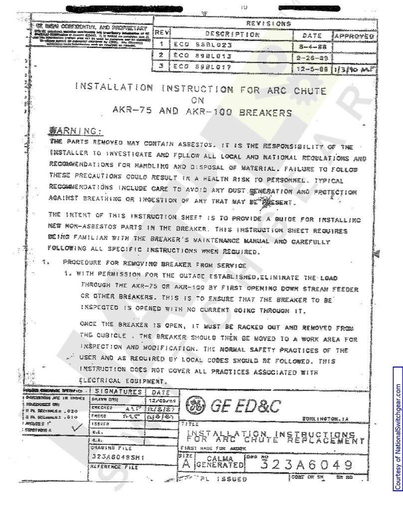
ARC
QUENCHER
Each
arc
quencher (see Fig. 3) has
several
compolJIld
inside
barriers
(2)
containing' a
large
number of
perforations
and two o\ltside
barriers
(3)
without
perforations,
as
well
as
a
front
cap
(4)
and
a
rear
support
(24)
held in place by afiber
strap
(23). Aclamp
(5)
is
attached to the
breaker
base
by
two
bOlts. Clamp
(5)
holds
all
the
arc
quencher
assemblies
to
their
respective pole units. Amuf-
fler
(1)
is
located on top
of
the compound
barriers.
The compound
barriers
and the muffler, together
with the
slots
between the
barriers,
serve
to
ex-
tinguish the
arc.
'
The
arc
quenchers
sh(ijJ],d
be inspected
at
the
regular
inspection period and'
parts
replaced,
if
badly burned
or
corroded.
REPLACEMENT, FIG. 3
1. Remove clamp
(5)
by removing two bOlts.
2. Unclasp
fiber
strap
(23).
3. Remove
front
cap (4), muffler (1), outside
barriers
(3), inside
barriers
(2)
and
rear
support (24).
4. Install new
or
disassembled
parts
in
re-
verse
order.
NOTE: In
re-assembling
the
rear
suppod
(24)
to the
breaker,
be
sure
and push the
rear
support
toward the top of the pole unit
so
that the
clearance
in the
rear
support will accommodate the
screw-
head
of
the back plate. .
POLE UNIT
ASSEMBLY
The contact assembly of each pole unit con-
sists
of astationary and amovable contact
sub-.
assembly.
Refer
to Fig. 6.
The stationary contact assembly consists of
parallel
contact fingers
(3)
with
silver
alloy tips,
the.
upper stud
(20)
and pins
(4)
with compression
springs
(19)
which provide continuous contact
pres-
sure
between the contact fingers and the upper
stud (20). Ashunt
(21)
is
used to
prevent
pitting
at
the pivot point
of
the
stationary
fingers when
carrying
high momentary
currents.
.The
station-
ary
contact fingers
are.
held in place by the upper
stud
cap(6).
.
The movable contact assembly
consists
of
parallel
contact
arms
(5)
with
silver
alloy tips, a
contact
carrier
(18)
with aspring
(17)
which
pro-
vides continuous contact between the contact
arms
and
Pin.
(11».
Aclamp
(14)
secures
pin
(15)
to the
contact support (16). Aflexible connection
(12)
is
provided to prevent pitting .at the pivot point of the
movable contact
arms
when
carrying
high
mO:D:\en-
.
tar:Y
currents.
The movable contact assembly
is
connected to
the
main
shaft (16), Fig. 3, by an insulating link
(7)
for
operating the contacts
'When
the
breaker
closes.
Adefinite amount of contact
pressure.
(see
"Meas-
uring Contact
Pressure")
must
be
exerted
by the
movable contacts
against
the stationary contacts.
Adefinite amount of contact wipe,
or
the distance
that the stationary contacts
are
pushed to the
rear
by the movable contacts (see "Measuring
CO;ntact
Wipe"), must
result
during the closing operation.
Both contact
pressure
and contact wipe should be
checked
at
the
regular
inspection period.
MEASURING
CONTACT PRESSURE, FIG. 6
1. Remove
arc
quencher (see "Replacements"
under Arc Quencher).
2.
Place
apush-type
scale
against
the upper
end of the stationary contact tip
(3)
with
the
breaker
closed.
3.
Exert
pressure
against the push-type
scale
until the contacts
just
part.
When the con-
tacts
part
the
scale
should
register
between
4and 6pounds.
4.
Re-assemble
parts
in
reverse
order.
MEASURING
CONTACT WIPE, FIG. 6
1. Remove
arc
quencher (see "Replacements"
under
Arc
Quencher). . .
2. Measure the dimension between the inside
surface
of the pole
base
and the top edge of
the stationary contact tip (3), (a) with the
breaker
open,
(b)
with the
breaker
closed.
3. The difference·between these two
measure-
ments should be within the
limits
of
3/32"
and 1/4'"
If
not
within this range, the con-
tact
wipe
must
be
adjusted.
4. With the
breaker
closed, the
stationary
con-
tacts
should have aminimum of 1/16"
overtravel,
measured
at
the contact tips,
before reaching the
limit
of
their
movement
in the
direction
of closing.
5. Replace
arc
quencher.
9
