Complete Solutions in Emergency Lighting STANILITE Complete Solutions in Emergency Lighting STANILITE
© Thomas & Betts (Australasia) Pty. Ltd. 2015 Rev: 6.0 2 November 2015 3© Thomas & Betts (Australasia) Pty. Ltd. 2015 Rev: 6.0 2 November 2015 2
12. This step is for Nexus LX or Nexus RF unit only. Once manually checked, it is ready for the commissioning into the Nexus network.
Keep the information details of this unit including exact location description, DB (distribution board) and CB (circuit breaker)
numbering, channel and router numbering, plan number and cross referencing information as all of this will be required for entry
into the database during commissioning. Refer to the Nexus LX User & Technical Guide for full details. As the installer, it is your
responsibility to conduct the initial discharge testing of the installed unit. Refer to AS/NZS 2293.
Important Note: 24 hours is required to allow the tting battery to reach full capacity, ie: prior to
a discharge test. As the installer, it is your responsibility to conduct the initial discharge testing of
the installed tting. Refer to AS/NZS2293.
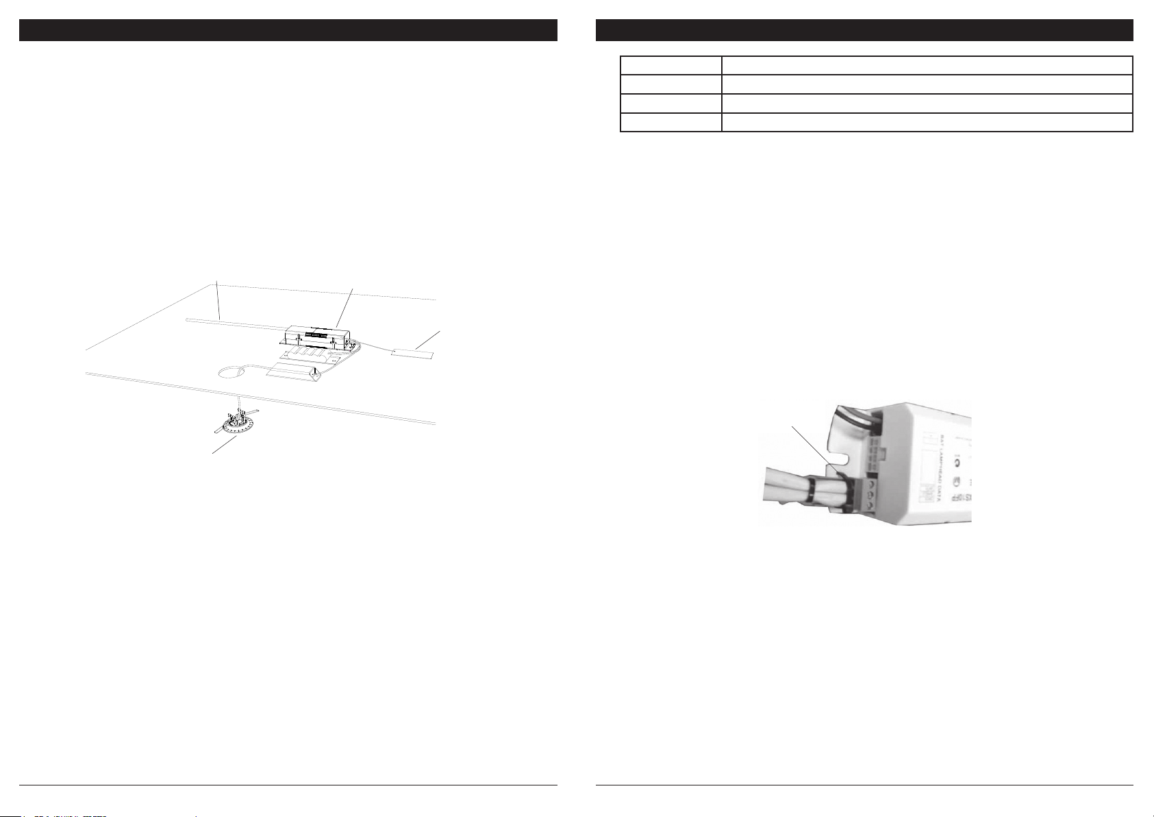
DATA CONNECTION
Connect the data cable as shown in gure 2 using suitably sized screwdriver. Ensure that the data cable/s are completely inserted into
the connector and properly secure with the cable tie.
Note: When correctly installed no tting should have more than 2 data cables connected to it. If you have more than 2 data cables at any
1 tting, the installation is incorrect. Consult the Nexus LX User & Technical Guide.
Warning: No mains carrying cables are to be connected to the data terminals or cables.
REMOVAL INSTRUCTIONS
1. Before removing the installed tting, de-energise and lock off the supply circuit.
2. Unplug the power cord from the mains socket.
3. Disconnect the battery and lamp head plug.
4. For Nexus LX product; unplug the data cable connector from the control pack.
TESTING PRECAUTIONS
Once the tting is permanently connected to the mains supply, a commissioning discharge test as required in AS/NZS2293.2 must be
carried out. You will need to allow 24 hours for the battery to fully charge prior to conducting this test, presently (at the time of writing),
the standard requires that ttings operate in emergency mode for a period not less than 2 hours for their commissioning test and for
not less than 90 minutes thereafter (it is required that 6 monthly discharge tests be carried out). You will need to keep the records for
the commissioning test and enter them into the building emergency services logbook or via other recording methods as allowed by
AS/NZ2293.2.
Fitting Type LED State - on initial powering - no tting faults
Non-monitored Solid red
Nexus LX Flashing green
Nexus RF Green ash with 2 red blinks, green ash with 3 red blinks
Figure 2: Data Connection
Cable tie to the base
of the unit to secure
Data Plug
INSTALLATION INSTRUCTIONS
1. Remove the unit from the packing box and inspect it for damage or imperfections. If any damage is found, do not install the unit,
but replace it carefully into the packing box and notify the Thomas & Betts Product Support Hotline in Australia on 1300 666 595.
2. If all looks okay, installation can proceed. Please note, the circuit supplying mains power to the tting must not be energised until
installation of the tting is completed.
3. Mark and cutout a hole in the ceiling to suit either small or large spitre head. The cut-out size for the standard lamp head is 50mm.
The cut-out size for a small 85mm adaptor plate is 70mm and for the large 141mm adaptor plate is 130mm. Note the adaptor plates
are mainly used for existing Spitre replacement or where access is limited.
4. Snap the lamp head to the appropriate adaptor plate (if used).
5. Connect the battery to the control pack, the battery pack can be attached to the control pack using cable tie supplied.
6. Connect data cable to the control pack.
7. Feed the battery and control pack assembly through the ceiling cut-out and secure them to a suitable location within the ceiling
space. If access to the ceiling cavity is not available, connect the mains power cord before recessing the battery and control pack
in the ceiling cut-out. Secure the battery and control pack to a suitable location within the ceiling space.
8. For Nexus LX product; refer to data connection section.
9. Nexus RF product; connect the antenna to the control pack. Collect the MAC address, by removing the peel off sticker section and
locating it on your oor plan or spreadsheet.
10. Connect ex and plug to the supply socket.
11. Check operation of the unit to ensure that the installation was successful. Once powered up, as a non-maintained tting the present
lamp stays off. Allow a few minutes to give the battery a small charge, then press the test button located at the spitre lamp head.
Hold the test button in for a few seconds and observe the operation of the lamp switching from mains to the emergency mode.
If the lamp on emergency mode works momentarily, that’s okay. Try again in a few more minutes in case battery is completely
discharged, it may take a little time to charge up enough to operate even momentarily. After this time, press the test button again
and if the lamp does not work at all, check the supply, the connections and follow the instruction given in the trouble shooting guide
at the end of this document. Operation modes of the LED status should be as follows:
Main control unit
Figure 1: Product installed in ceiling
LED Spitre lamp head
with 85mm adaptor
Antenna - for
RF product only.
Keep away from
metal parts or
steel structure
Power cable


