Complete Solutions in Emergency Lighting STANILITE Complete Solutions in Emergency Lighting STANILITE
© Thomas & Betts (Australasia) Pty. Ltd. 2016 Rev: 7.0 22 February 2016 2 © Thomas & Betts (Australasia) Pty. Ltd. 2016 Rev: 7.0 22 February 2016 3
INSTALLATION INSTRUCTIONS
1. Remove the unit from the packing box and inspect it for damage or imperfections. If any damage is found, do not install the unit,
but replace it carefully into the packing box and notify the Thomas & Betts Product Support Hotline in Australia on 1300 666 595.
2. If all looks okay, proceed for installation. Take the mounting bracket and whilst holding it into place against the ceiling or wall, use
a pencil to mark the position of the screw holes (at A or B in Figure 2) and cable entry position through the bracket onto the ceiling
or wall as appropriate. Make sure to allow at least 50mm of free space to the right hand side of the nal location of the unit to allow
for the sliding function of attaching the unit to the mounting bracket. If need be, turn the bracket around and swap the diffuser with
the back plate to permit room for inserting and removing the unit from the mounting bracket. Orient the bracket in such a way as to
make the LED and push button readily visible and accessible when the unit is installed.
3. Remove the bracket to reveal the pencil marks and if the cabling is to be concealed, drill a 20mm hole for the cable entry prior to
installing the bracket. Make sure the mounting screw locations are into solid material and strong enough to support the weight of
the complete unit, (approx 2kg; build-up, strengthen or support the mounting material if necessary) and attach the bracket. Because
of the wide variety of building construction materials and the wide variety of screw fasteners appropriate to each type, mounting
screws are not provided with the unit. If appropriate and safe, drill and use your own xing holes in the mounting bracket to suit the
individual installation location and structural support needs of the unit. Taking care not to obstruct the tting slide entry.
4. Run the cables in the ceiling or wall space as appropriate or surface mounted in conduit and through the cable hole into the
bracket. Strip, connect and terminate the cables as indicated in Figure 1. Ensure that the double insulation of the cable/s passes
completely into the terminal block enclosure so that no single insulation is exposed when the cover is in place. The hole plug set
includes a suitable bush to mechanically protect the cable as it passes through the opening in the mounting bracket. Likewise, the
single insulation of the conductors should run right up to the metal edge of the terminals leaving no bare conductors outside of
the terminals. Be careful with multi strand conductors that all of the strands are twisted together before insertion into the terminal.
Any stray strands that inadvertently come into contact with their neighbouring terminal or the metal frame of the tting will cause
undesirable results when the tting is powered.
Figure 1: Quickt Terminal Block Connection
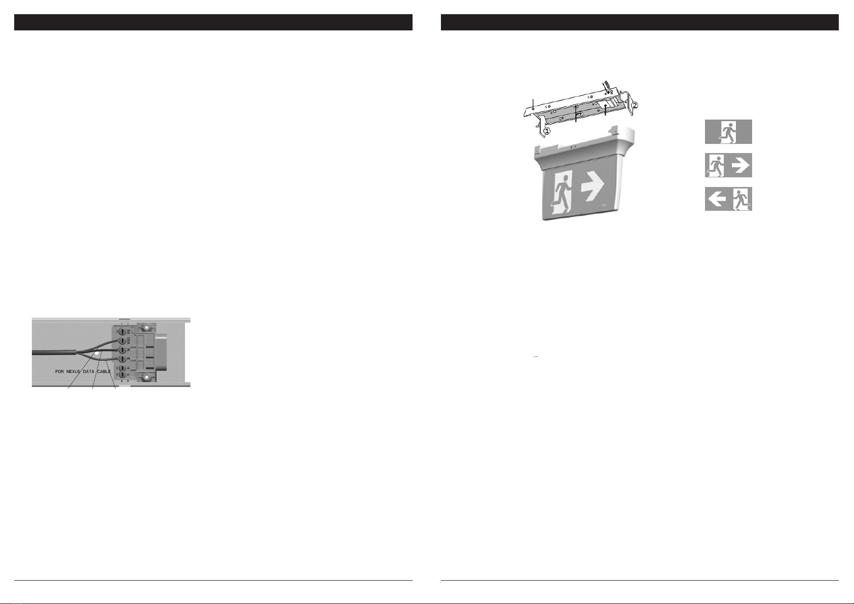
5. Fit the diffuser assembly to the body of the unit (if not already in place). Attach the unit to the mounting bracket by aligning the top
left hand end of the unit (the end without the protruding electrical connecting metal lugs) with the large cut-away slot towards the
left hand end of the bracket. Slip the left hand end of the unit up into the slot in the left hand end of the bracket (Step (1) in Figure
2) and hold the unit horizontal to and parallel with the bracket. It should be approximately 50mm to the right of its nal destination.
Simply slide the unit (Step (2) in Figure 2) 50mm to the left along and into the bracket to engage the connections and the locking
tab. Once in place, the unit cannot be removed from the bracket without the use of a tool (a small screwdriver) to push in the locking
tab at ‘D’ in Figure 2. Ensure the correct pictograph inserts have been attached to the diffuser assembly.
6. Once powered up, the normal AC LED light source will energise and remain lit until the power supply fails. The emergency function
of the light tting will only operate when the normal lighting power supply fails or when somebody presses the manual test button
located on the front of the unit. Red LED indicates that the power is connected and the battery is charging.
7. Check the operation of the unit to ensure that the installation was successful. When powered up, allow a few minutes to give the
battery a small charge, then press the manual test button located at the front face of the unit. Hold the test button in for a few
seconds and observe the operation of the LED light source switching from mains to the emergency mode. If the LED light source
on emergency mode works momentarily, that’s okay. Try again in a few more minutes because if the battery was completely
discharged, it may take a little time to charge up enough to operate even momentarily. After this time, press the test button again
and if the LED light source doesn’t work at all, check the supply, the connections and the trouble shooting guide at the end of this
document.
Figure 2: Quickt Insertion Diagram & Internal View
Important Note: If installing this product into an early version ceiling bracket, rst remove the two
hole blanking plugs on the front face of the bracket and replace with the short hole plugs provided
with the product.
REMOVAL INSTRUCTIONS
Gently insert a small screwdriver into the slot (at ‘D’ in Figure 2) on the front of the bracket towards the right hand end of the tting, to ease
the locking tab into the tting and away from the bracket. The unit is then free to slide to the right along the bracket for about 50mm, at
which time the slots line up and it can be lowered away from the bracket, allowing the two to separate. The unit will automatically switch
into emergency mode because it has been removed from the power supply. It will stay on emergency until such time as the battery cut
off threshold is reached or it is reconnected back onto the power supply, whichever happens rst. When the unit is reconnected to the
supply, it will need time to recharge its battery before it will be capable of a full length discharge again. The ability of the unit to operate
on emergency is determined by the age, charge level, operating temperature conditions and environmental circumstances of the battery
in the unit.
TESTING PRECAUTIONS
Once the tting is permanently connected to the mains supply, a commissioning discharge test as required in AS/NZS2293.2 must be
carried out. You will need to allow 24 hours for the battery to fully charge prior to conducting this test, presently (at the time of writing),
the standard requires that ttings operate in emergency mode for a period not less than 2 hours for their commissioning test and for
not less than 90 minutes thereafter (it is required that 6 monthly discharge tests be carried out). You will need to keep the records for
the commissioning test and enter them into the building emergency services logbook or via other recording methods as allowed by
AS/NZ2293.2.
CONSTRUCTION SITES
Continuously switching of the mains power supply that is connected to emergency light ttings during the construction phase of an
installation will cause these ttings to discharge and charge their batteries many times over a short period; this can shorten the life of the
battery and will also result in shortened emergency lamp life for uorescent ttings. Thomas & Betts does not recommend such practices
and may not honour the warranty on batteries when they are subjected to such harsh operating conditions. Emergency light ttings are
designed to be discharge tested once every 6 months as per AS/NZS2293.2, subjecting the product to repeated discharge or charge
cycles is regarded as an abuse of the ttings.
• LED Legend Quikt maintained ttings are design for
permanent illumination: Connect incoming unswitched
active, neutral and earth to terminal marked USA, N and E
respectively.
• Data connection for Nexus LX product installation:
• The same colour wire from each data cables connects to the
terminal marked +
• The other colour wire from each of the data cables connects
to the terminal marked -
• When connected, replace the terminal block cover so that it
clicks and locks into place.
• No mains or mains carrying cables are to be connected to the
data terminals or cables.
Active Neutral Earth
Quickt
Mounting
Bracket
Insert here
to remove
Terminal Block
For Ceiling Mount
Screw through holes
labelled ‘A’
For Wall Mount
Screw through holes
labelled ‘B’ via slot ‘C’
To t unit to Mounting
Bracket Insert at 1 then 2
Cable Entry
Holes


